1
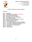
ERV Trailer System
User’s Manual
E.H. Wachs
600 Knightsbridge Parkway
Lincolnshire, IL 60069
www.ehwachs.com
E.H. Wachs Part No. 79-MAN-20
Rev. 1-0911, September, 2011
Revision History:
Original: November, 2009
Revision 1:September, 2011
Copyright © 2011 E.H. Wachs. All rights reserved.
This manual may not be reproduced in whole or in part
without the written consent of E.H. Wachs.
ERV Trailer System
This page intentionally left blank.
Part No. 79-MAN-20, Rev. 1-0911
E.H. Wachs
Table of Contents
Table of Contents
Chapter 1: About This Manual . . . . . . . . . . . . . . . . . . . . . . . . . . . . . . . . . . . . . . . . . . . . . . . . . 1
Purpose of This Manual . . . . . . . . . . . . . . . . . . . . . . . . . . . . . . . . . . . . . . . . . . . . . . . . . . . . . . . . . 1
How to Use The Manual . . . . . . . . . . . . . . . . . . . . . . . . . . . . . . . . . . . . . . . . . . . . . . . . . . . . . . . . 1
Symbols and Warnings . . . . . . . . . . . . . . . . . . . . . . . . . . . . . . . . . . . . . . . . . . . . . . . . . . . . . . . . . 2
Manual Updates and Revision Tracking . . . . . . . . . . . . . . . . . . . . . . . . . . . . . . . . . . . . . . . . . . . . 3
Component Manuals . . . . . . . . . . . . . . . . . . . . . . . . . . . . . . . . . . . . . . . . . . . . . . . . . . . . . . . . . . . 3
Chapter 2: Safety . . . . . . . . . . . . . . . . . . . . . . . . . . . . . . . . . . . . . . . . . . . . . . . . . . . . . . . . . . . . . 5
Operator Safety . . . . . . . . . . . . . . . . . . . . . . . . . . . . . . . . . . . . . . . . . . . . . . . . . . . . . . . . . . . . . . . 5
Safety Symbols . . . . . . . . . . . . . . . . . . . . . . . . . . . . . . . . . . . . . . . . . . . . . . . . . . . . . . . . . . . . 6
Protective Equipment Requirements . . . . . . . . . . . . . . . . . . . . . . . . . . . . . . . . . . . . . . . . . . . . 7
Safety Labels . . . . . . . . . . . . . . . . . . . . . . . . . . . . . . . . . . . . . . . . . . . . . . . . . . . . . . . . . . . . . . . . . 7
Chapter 3: Introduction to the Equipment . . . . . . . . . . . . . . . . . . . . . . . . . . . . . . . . . . . . . . . 11
Standard Equipment . . . . . . . . . . . . . . . . . . . . . . . . . . . . . . . . . . . . . . . . . . . . . . . . . . . . . . . . . . . 11
Optional Equipment . . . . . . . . . . . . . . . . . . . . . . . . . . . . . . . . . . . . . . . . . . . . . . . . . . . . . . . . 11
Trailer . . . . . . . . . . . . . . . . . . . . . . . . . . . . . . . . . . . . . . . . . . . . . . . . . . . . . . . . . . . . . . . . . . . . . . 15
Trailer Assembly . . . . . . . . . . . . . . . . . . . . . . . . . . . . . . . . . . . . . . . . . . . . . . . . . . . . . . . . . . 15
Engine . . . . . . . . . . . . . . . . . . . . . . . . . . . . . . . . . . . . . . . . . . . . . . . . . . . . . . . . . . . . . . . . . . . . . 18
Hydraulic Power Unit . . . . . . . . . . . . . . . . . . . . . . . . . . . . . . . . . . . . . . . . . . . . . . . . . . . . . . . . . 19
ERV-750 Extended Reach Valve Exerciser . . . . . . . . . . . . . . . . . . . . . . . . . . . . . . . . . . . . . . . . 21
Storage . . . . . . . . . . . . . . . . . . . . . . . . . . . . . . . . . . . . . . . . . . . . . . . . . . . . . . . . . . . . . . . . . . . . . 22
Key Storage . . . . . . . . . . . . . . . . . . . . . . . . . . . . . . . . . . . . . . . . . . . . . . . . . . . . . . . . . . . . . . 22
Storage Basket . . . . . . . . . . . . . . . . . . . . . . . . . . . . . . . . . . . . . . . . . . . . . . . . . . . . . . . . . . . . 23
Optional Equipment . . . . . . . . . . . . . . . . . . . . . . . . . . . . . . . . . . . . . . . . . . . . . . . . . . . . . . . . . . . 24
Hydraulic Hose Reel . . . . . . . . . . . . . . . . . . . . . . . . . . . . . . . . . . . . . . . . . . . . . . . . . . . . . . . 24
Light Bar . . . . . . . . . . . . . . . . . . . . . . . . . . . . . . . . . . . . . . . . . . . . . . . . . . . . . . . . . . . . . . . . 25
Chapter 4: Operating Instructions . . . . . . . . . . . . . . . . . . . . . . . . . . . . . . . . . . . . . . . . . . . . . . 27
Trailer Features . . . . . . . . . . . . . . . . . . . . . . . . . . . . . . . . . . . . . . . . . . . . . . . . . . . . . . . . . . . . . . 27
Towing the Trailer . . . . . . . . . . . . . . . . . . . . . . . . . . . . . . . . . . . . . . . . . . . . . . . . . . . . . . . . . 27
Starting and Running the Engine . . . . . . . . . . . . . . . . . . . . . . . . . . . . . . . . . . . . . . . . . . . . . . . . . 28
Using the Hydraulic System . . . . . . . . . . . . . . . . . . . . . . . . . . . . . . . . . . . . . . . . . . . . . . . . . . . . 29
Valve Exerciser . . . . . . . . . . . . . . . . . . . . . . . . . . . . . . . . . . . . . . . . . . . . . . . . . . . . . . . . . . . . . . 31
Light Bar Operation . . . . . . . . . . . . . . . . . . . . . . . . . . . . . . . . . . . . . . . . . . . . . . . . . . . . . . . . . . . 34
E.H. Wachs
Part No. 79-MAN-20, Rev. 1-0911
i
ERV Trailer System
Chapter 5: Routine Maintenance . . . . . . . . . . . . . . . . . . . . . . . . . . . . . . . . . . . . . . . . . . . . . . .
Hydraulic System . . . . . . . . . . . . . . . . . . . . . . . . . . . . . . . . . . . . . . . . . . . . . . . . . . . . . . . . . . . .
Engine . . . . . . . . . . . . . . . . . . . . . . . . . . . . . . . . . . . . . . . . . . . . . . . . . . . . . . . . . . . . . . . . . . . . .
Replacing Switches and Fuses . . . . . . . . . . . . . . . . . . . . . . . . . . . . . . . . . . . . . . . . . . . . . . . . . . .
Replacing Light Bar and Work Light Bulbs . . . . . . . . . . . . . . . . . . . . . . . . . . . . . . . . . . . . . . . .
Light Bar Flashers . . . . . . . . . . . . . . . . . . . . . . . . . . . . . . . . . . . . . . . . . . . . . . . . . . . . . . . . .
Work Lights . . . . . . . . . . . . . . . . . . . . . . . . . . . . . . . . . . . . . . . . . . . . . . . . . . . . . . . . . . . . . .
37
37
38
39
41
41
42
Chapter 6: Parts List and Ordering Information . . . . . . . . . . . . . . . . . . . . . . . . . . . . . . . . . .
Ordering Replacement Parts . . . . . . . . . . . . . . . . . . . . . . . . . . . . . . . . . . . . . . . . . . . . . . . . . . . .
Repair Information . . . . . . . . . . . . . . . . . . . . . . . . . . . . . . . . . . . . . . . . . . . . . . . . . . . . . . . . . . .
Warranty Information . . . . . . . . . . . . . . . . . . . . . . . . . . . . . . . . . . . . . . . . . . . . . . . . . . . . . . . . .
Return Goods Address . . . . . . . . . . . . . . . . . . . . . . . . . . . . . . . . . . . . . . . . . . . . . . . . . . . . . . . . .
Parts Lists and Drawings . . . . . . . . . . . . . . . . . . . . . . . . . . . . . . . . . . . . . . . . . . . . . . . . . . . . . . .
43
43
44
44
44
45
ii
Part No. 79-MAN-20, Rev. 1-0911
E.H. Wachs
Chapter 1, About This Manual
Chapter 1
About This Manual
PURPOSE OF THIS MANUAL
This manual explains how to operate and maintain the ERV
Trailer System and hydraulic power unit. It includes
instructions for set-up, operation, and maintenance, in addition to parts lists, diagrams, and service information to be
used when ordering replacement parts and performing userserviceable repairs.
In This Chapter
PURPOSE OF THIS MANUAL
HOW TO USE THE MANUAL
SYMBOLS AND WARNINGS
MANUAL UPDATES AND
REVISION TRACKING
COMPONENT MANUALS
Before operating the ERV Trailer System, read through this
manual and become familiar with all instructions. Also read
the manual for the gas engine that powers the hydraulic
power unit; this manual describes how to service and maintain the engine.
HOW TO USE THE MANUAL
This manual is organized so that information can be found
quickly and easily. Each chapter describes a specific topic
on using or maintaining your equipment.
Throughout this manual, refer
to this column for warnings,
cautions, and notices with
supplementary information.
Each page is designed with two columns. The large column
on the inside of the page contains instructions and illustrations. Use these instructions to operate and maintain the
equipment.
The narrower column on the outside contains additional
information such as warnings, special notes, and defini-
E.H. Wachs
Part No. 79-MAN-20, Rev. 1-0911
1
ERV Trailer System
tions. Refer to the narrow column for safety notes and other
information.
SYMBOLS AND WARNINGS
The following symbols are used throughout this manual to
indicate special notes and warnings. They appear next to the
section that they refer to, in the outside column of the page,
It is important to understand what each symbol means, and
follow all instructions for cautions and warnings.
WARNING
A WARNING alert with the
safety alert symbol indicates
a potentially hazardous situation that could result in serious injury or death.
This is the safety alert symbol and is
used to notify the user of potential personal injury hazards. Obey all safety
messages that follow this symbol to avoid
possible injury or death.
CAUTION
A CAUTION alert with the
safety alert symbol indicates
a potentially hazardous situation that could result in
minor or moderate injury.
CAUTION
A CAUTION alert with the
damage alert symbol indicates a situation that will
result in damage to the
equipment.
2
This is the equipment damage alert
symbol and is used to notify the user of
potential equipment damage situations. Obey all messages that follow this
symbol to avoid damaging the equipment
or work piece on which it is operating.
Part No. 79-MAN-20, Rev. 1-0911
E.H. Wachs
Chapter 1, About This Manual: Manual Updates and Revision Tracking
IMPORTANT
An IMPORTANT alert with
the damage alert symbol indicates a situation that may
result in damage to the
equipment.
NOTE
NOTE
This symbol indicates a user note. Notes
provide additional information to supplement the instructions, or tips for easier
operation.
A NOTE provides supplementary information or operating tips.
MANUAL UPDATES AND REVISION TRACKING
Occasionally, manuals will be updated with improved operation or maintenance procedures, or with corrections if necessary. Revised manuals will include an updated revision
history on the title page.
If factory service or upgrades are performed on the equipment and that service changes any technical data or operation and maintenance procedures on the equipment, a
revised manual will be returned with the equipment.
Current versions of E.H.
Wachs manuals are also
available in PDF format. You
can request an electronic
copy of this manual by emailing customer service at
[email protected].
COMPONENT MANUALS
The following manufacturers’ manuals are supplied for
components of the ERV Trailer System:
•
•
Engine Owner’s Manual (for gas engine)
Dexter Hubs/Drums/Bearings manual
E.H. Wachs
Part No. 79-MAN-20, Rev. 1-0911
3
ERV Trailer System
This page intentionally left blank.
4
Part No. 79-MAN-20, Rev. 1-0911
E.H. Wachs
Chapter 2, Safety
Chapter 2
Safety
In This Chapter
E.H. Wachs takes great pride in designing and manufacturing safe, high-quality products. We make user safety a top
priority in the design of all our products.
OPERATOR SAFETY
SAFETY LABELS
Read this chapter carefully before operating the ERV
Trailer System. It contains important safety instructions and
recommendations.
Also refer to safety information in the gas engine manual.
OPERATOR SAFETY
Follow these guidelines for safe operation of the equipment.
•
•
•
READ THE OPERATING MANUAL. Make sure
you understand all setup and operating instructions
before you begin.
INSPECT MACHINE AND ACCESSORIES.
Before starting the machine, look for loose bolts or
nuts, leaking lubricant, rusted components, and any
other physical conditions that may affect operation.
Properly maintaining the machine can greatly decrease
the chance for injury.
ALWAYS READ PLACARDS AND LABELS. Make
sure all placards, labels, and stickers are clearly legible
and in good condition. You can purchase replacement
labels from E.H. Wachs.
E.H. Wachs
Part No. 79-MAN-20, Rev. 1-0911
Look for this symbol throughout the
manual. It indicates
a personal injury
hazard.
5
ERV Trailer System
•
•
•
KEEP CLEAR OF MOVING PARTS. Keep hands,
arms, and fingers clear of all rotating or moving parts.
Always turn machine off before doing any adjustments
or service.
SECURE LOOSE CLOTHING AND JEWELRY.
Secure or remove loose-fitting clothing and jewelry, and
securely bind long hair, to prevent them from getting
caught in moving parts of the machine.
KEEP WORK AREA CLEAR. Keep all clutter and
nonessential materials out of the work area. Only personnel directly involved with the work being performed
should have access to the area.
Safety Symbols
This icon is displayed with any safety alert that indicates a
personal injury hazard.
WARNING
This safety alert indicates a potentially hazardous situation
that, if not avoided, could result in death or serious injury.
CAUTION
This safety alert, with the personal injury hazard symbol,
indicates a potentially hazardous situation that, if not
avoided, could result in minor or moderate injury.
6
Part No. 79-MAN-20, Rev. 1-0911
E.H. Wachs
Chapter 2, Safety: Safety Labels
Protective Equipment Requirements
WARNING
Always wear impact resistant eye protection while operating or working near
this equipment.
For additional information on eye and face protection, refer
to Federal OSHA regulations, 29 Code of Federal Regulations, Section 1910.133., Eye and Face Protection and
American National Standards Institute, ANSI Z87.1, Occupational and Educational Eye and Face Protection. Z87.1 is
available from the American National Standards Institute,
Inc., 1430 Broadway, New York, NY 10018.
CAUTION
Personal hearing protection is recommended when operating or working near
this tool.
Hearing protectors are required in high noise areas, i.e. 85
dBA or greater. Noise level can be increased by the operation of other tools and equipment in the area, reflective surfaces, process noises, and resonant structures. For additional
information on hearing protection, refer to Federal OSHA
regulations, 29 Code of Federal Regulations, Section
1910.95, Occupational Noise Exposure and ANSI S12.6
Hearing Protectors.
SAFETY LABELS
The following safety labels are included on the ERV Trailer
System. (Some labels are associated with optional equipment.) Ensure that all labels are in good condition and legible. Replace any damaged or missing labels. To order
replacements, refer to the part numbers in this section and
see the ordering instructions in Chapter 6.
E.H. Wachs
Part No. 79-MAN-20, Rev. 1-0911
7
ERV Trailer System
Figure 2-1. This warning label is on the top of both
trailer fenders. Do not step on the trailer fender to
reach any part of the equipment. (Part no. 59-084-00)
Figure 2-2. The safety chain warning label is on the
tongue of the trailer. (Part no. 77-106-20)
Figure 2-3. This warning label is on the back of both
trailer fenders. Prior to each use of the trailer, check
tire condition and lug nut tightness. (Part no. 77-16015)
8
Part No. 79-MAN-20, Rev. 1-0911
E.H. Wachs
Chapter 2, Safety: Safety Labels
Figure 2-4. This label is on the hydraulic hose reel.
When retracting the hose, walk it back to the reel. Do
not let the hose snap back into the reel. (Contact the
manufacturer, Cox Reels, for replacement labels.)
Figure 2-5. This caution label is on the hydraulic
hose reel. Do not disassemble the spring from the reel.
Figure 2-6. This warning label is on the ERV head.
Before moving the ERV from the stow position, ensure
that the trailer is connected to a tow vehicle (Part no.
79-020-00-01.)
E.H. Wachs
Part No. 79-MAN-20, Rev. 1-0911
9
ERV Trailer System
This page intentionally left blank.
10
Part No. 79-MAN-20, Rev. 1-0911
E.H. Wachs
Chapter 3, Operating Instructions
Chapter 3
Introduction to the
Equipment
In This Chapter
STANDARD EQUIPMENT
STANDARD EQUIPMENT
TRAILER
The following standard equipment is provided with the
basic 79-000-20 (gas engine) configuration of the ERV
Trailer System:
ENGINE
•
•
•
trailer
gas engine
hydraulic system
•
•
ERV-750 valve exerciser
storage basket
HYDRAULIC POWER UNIT
ERV-750 EXTENDED REACH
VALVE EXERCISER
STORAGE
OPTIONAL EQUIPMENT
Optional Equipment
The following optional equipment is available for the ERV
Trailer System:
•
•
hose reel with 45’ of hydraulic hose
direction control and worklight bar
These components are described in the following sections.
E.H. Wachs
Part No. 79-MAN-20, Rev. 1-0911
11
ERV Trailer System
ERV-750
valve
exerciser
Light bar controller
Voltage meter and work light
Hydraulic tank and control panel
Figure 3-1. The right side of the ERV Trailer System.
12
Part No. 79-MAN-20, Rev. 1-0911
E.H. Wachs
Chapter 3, Operating Instructions: Standard Equipment
Fuel tank
Engine
Hydraulic hose reel
Figure 3-2. The left side of the ERV Trailer System.
E.H. Wachs
Part No. 79-MAN-20, Rev. 1-0911
13
ERV Trailer System
ERV-750
valve
exerciser
Storage box
Hydraulic hose reel
Hydraulic tank
Figure 3-3. The rear view of the ERV Trailer System.
14
Part No. 79-MAN-20, Rev. 1-0911
E.H. Wachs
Chapter 3, Operating Instructions: Trailer
TRAILER
The ERV Trailer System is a single-axle trailer featuring allsteel construction with a box-beam frame and steel deck.
Specifications
Curb Weight:
1200 lbs
Tongue Weight:
200 lbs
Length:
10 ft
Width:
5.5 ft
Height:
6 ft
Trailer Assembly
To reduce shipping volume when shipped via common carrier, the trailer package is typically delivered without the
tongue installed. Unpack and inspect all components for
damage. If any damage is found, immediately report the
damage to the shipping company and your sales representative.
WARNING
Use ONLY purpose built
jacks and jack stands when
assembling or servicing the
trailer.
Do not use shipping material and/or shipping supports to
support any part of the trailer during tongue installation or
trailer service. Use ONLY purpose built jack stands and
jacks. Use the following procedure to install the tongue and
connect the wiring harness for the trailer lights.
1. Position tongue such that the jack is on the left side of
the tongue with the safety chain label facing up.
2. Carefully insert the tongue into the receiver, wires
first. Take care not to damage the wire and connectors.
E.H. Wachs
Part No. 79-MAN-20, Rev. 1-0911
CAUTION
The tongue assembly weighs
65 lbs and should be installed
using two people.
15
ERV Trailer System
3. Line up the holes in the tongue with the holes in the
receiver. Insert bolts and tighten supplied nuts to 80
lb*ft.
Figure 3-4. Tighten nuts to secure tongue to trailer.
4. Route tongue wires through frame hole as shown in
Fig. 3-5. Fold ground wire (white) back and insert the
four wire connector through the hole. Use care to
avoid breaking the locking tab on the connector. Once
the large connector is through, pull the wire harness
through until the ground wire and connector clears the
frame.
Figure 3-5. Route tongue connectors through frame.
16
Part No. 79-MAN-20, Rev. 1-0911
E.H. Wachs
Chapter 3, Operating Instructions: Trailer
5. Place the ground wire on the stud welded to the frame.
Install and tighten the lock nut.
Figure 3-6. Attach ground wire to stud.
6. Connect the four wire connectors. A “click” should be
heard indicating the connection is complete. The
green weather seal should be fully encased in the mating connector, leaving only a thin ring visible.
Figure 3-7. Connect four wire connectors.
7. Verify proper operation of the trailer lights.
8. Safely remove jack stands and lower the trailer.
E.H. Wachs
Part No. 79-MAN-20, Rev. 1-0911
17
ERV Trailer System
ENGINE
The trailer’s equipment is powered by a 16 HP Briggs &
Stratton Vanguard V-Twin gasoline engine. This overhead
cam, horizontal crankshaft engine is equipped with an electric starter. The engine operates the ERV-750 and hydraulic
pump.
The engine operates on 87 octane unleaded gasoline or on
10% ethanol/90% gasoline “gasohol” blend. Use a winter
blend fuel when running the engine in cold weather.
The engine is provided with an Owner’s Manual a. Refer to
the manual for operating guidelines, maintenance, and service of the engine.
Figure 3-8. The gasoline engine for the ERV Trailer
System.
18
Part No. 79-MAN-20, Rev. 1-0911
E.H. Wachs
Chapter 3, Operating Instructions: Hydraulic Power Unit
HYDRAULIC POWER UNIT
The hydraulic power unit is designed to supply hydraulic
power to the ERV-750 valve exerciser, other Wachs utility
tools (except the Trav-L-Cutter), or any HTMA Class II
hydraulic tool. It supplies 8 gallons per minute (gpm) flow
at a pressure of 2000 psi.The 10 gallon hydraulic oil reservoir has a sight gauge for oil level and temperature. The system includes an auxiliary power port, relief valve, and an oil
cooler with an electric fan.
Specifications
Hydraulic supply
8 gpm at 2000 psi
Engine performance
16 horsepower
4 hour fuel endurance
Hydraulic reservoir
10 gallons (37.8 l)
Filtration
10 micron canister filter
Finish
Powder coated white
The hydraulic power unit is shown in the following figures:
Figure 3-9 (components of the hydraulic power unit),
Figure 3-10 (front panel controls), and Figure 3-11 (engine
controls).
Engine
Engine gas tank
Hydraulic reservoir cap
Hydraulic fluid filter
Figure 3-9. Components of the hydraulic power unit.
E.H. Wachs
Part No. 79-MAN-20, Rev. 1-0911
19
ERV Trailer System
Selector knob; pull
for hose reel, push
for ERV-750
Engine
hours
gauge
Hydraulic
oil level/
temp gauge
Hydraulic
pressure
Engine keyswitch
Hydraulic
ports: return (tank) pressure
Port selector knob; pull for
auxiliary ports; push for
ERV-750 and hose reel.
Figure 3-10. Front panel of the hydraulic power unit.
Throttle
Choke
Electrical port
(to ERV-750)
Figure 3-11. Front panel engine controls.
20
Part No. 79-MAN-20, Rev. 1-0911
E.H. Wachs
Chapter 3, Operating Instructions: ERV-750 Extended Reach Valve Exerciser
ERV-750 EXTENDED REACH VALVE
EXERCISER
The ERV-750 is an extended-reach hydraulic valve exerciser mounted on a pivoting, telescoping arm. It can reach
valves up to 13 ft from the curb side of the trailer, and provides up to 750 lb-ft of torque.
CAUTION
Do not move the ERV-750
from the stow position for
operation or service without
the trailer connected to a tow
vehicle.
Figure 3-12. The ERV-750 valve exerciser extends on
a pivoting, telescoping arm.
The ERV-750 includes a ruggedized handheld controller/
data logger for operating the machine and collecting valve
exercising data. The controller is available with optional
GPS capability (either standard or submeter resolution) for
automated valve locating and logging.
The controller is available separately (79-410-00) if a spare
or replacement is needed.
The ERV-750 is supplied with a separate manual for operating instructions and parts/service information.
E.H. Wachs
Part No. 79-MAN-20, Rev. 1-0911
21
ERV Trailer System
STORAGE
Key Storage
Additional storage for valve keys is located beneath the
trailer decking on both the left and right sides of the trailer.
Access the storage compartments by pulling the knob up
and opening the cover toward the inside of the trailer.
Figure 3-13. Additional key storage is located
beneath the decking at the rear of the trailer.
Figure 3-14. Access key storage by pulling the knob
up and opening the cover toward the inside of the
trailer.
22
Part No. 79-MAN-20, Rev. 1-0911
E.H. Wachs
Chapter 3, Operating Instructions: Storage
Storage Basket
A storage basket for holding valve keys and other tools is
mounted at the rear of the trailer frame.
Storage
basket
Figure 3-15. The storage basket is mounted at the
rear of the trailer.
E.H. Wachs
Part No. 79-MAN-20, Rev. 1-0911
23
ERV Trailer System
OPTIONAL EQUIPMENT
The following equipment items are options available with
the ERV Trailer System. The trailer can be equipped with
any combination of these options.
Hydraulic Hose Reel
The hose reel supplies 45 ft of 1/2” hydraulic hose (rated
2000 psi) for operating auxiliary equipment. It is plumbed
directly to the hydraulic tank and includes quick disconnect
fittings to connect to auxiliary tools.
NOTE
The hydraulic hoses are 45
feet long. The hose reel has a
ratchet lock; pull the desired
length of hose, then stop
when the ratchet clicks.
Hydraulic
hose reel
Figure 3-16. The hydraulic hose reel is mounted at
the rear of the trailer.
24
Part No. 79-MAN-20, Rev. 1-0911
E.H. Wachs
Chapter 3, Operating Instructions: Optional Equipment
Light Bar
An overhead light bar with work lights and a programmed
arrow board is available. The light bar includes an electronic control panel in a watertight enclosure.
Figure 3-17. The optional direction control and work
light.
Light bar controller
Figure 3-18. The light bar controller is housed in a
water-tight enclosure above the hydraulic unit.
E.H. Wachs
Part No. 79-MAN-20, Rev. 1-0911
25
ERV Trailer System
This page intentionally left blank.
26
Part No. 79-MAN-20, Rev. 1-0911
E.H. Wachs
Chapter 4, Operating Instructions
Chapter 4
Operating
Instructions
In This Chapter
This chapter provides instructions for towing the ERV
Trailer System and starting the engine to power the trailer’s
equipment.
Specific sections of the chapter provide instructions for
operating the following standard and optional components
of the ERV Trailer System:
• gas engine
• hydraulic system
• valve exerciser
• light bar
TRAILER FEATURES
STARTING AND RUNNING THE
ENGINE
USING THE HYDRAULIC
SYSTEM
VALVE EXERCISER
LIGHT BAR OPERATION
TRAILER FEATURES
Towing the Trailer
Before towing the trailer:
• Remove the key from the engine keyswitch.
• Ensure that the:
- hitch is properly attached and the safety chains are
attached to the vehicle.
- trailer tail lights, brake lights, and turn signals are
functional.
- jack stand on the trailer hitch is raised.
- tires are properly inflated.
- all hoses and attachments are securely stored on the
trailer.
• the ERV-750 is secured to the trailer bed with the
latches, remove the controller from its cradle and put it
in its storage case. Store the case in the vehicle.
E.H. Wachs
Part No. 79-MAN-20, Rev. 1-0911
27
ERV Trailer System
STARTING AND RUNNING THE ENGINE
NOTE
The engine MUST be running
to operate the valve exerciser
or auxiliary hydraulic equipment.
1. Ensure that there is sufficient fuel in the gas tank.
2. Pull the throttle halfway out.
3. If the engine is cold, pull the choke out.
Throttle
Choke
CAUTION
Use short starting cycles with
the keyswitch. Prolonged
cranking (more than 15 seconds) can damage the starter
motor.
Figure 4-1. To start the engine, pull the throttle halfway out. If the engine is cold, also pull the choke out.
4. Turn the keyswitch on the front panel to START.
When the engine starts, release the keyswitch back to
the RUN position.
Figure 4-2. Turn the key to START, then release to
RUN when the engine starts.
5. Allow the engine to run at least a minute to warm up.
Push the choke back in.
28
Part No. 79-MAN-20, Rev. 1-0911
E.H. Wachs
Chapter 4, Operating Instructions: Using the Hydraulic System
USING THE HYDRAULIC SYSTEM
Only one hydraulic circuit operates at a time. The ERV-750
is connected directly to the power unit, no hose connections
are required. When equipped with the optional hose reel,
auxiliary tools may be connected to either the hose reel hose
or the auxiliary ports located on the front panel.
To avoid damage to the equipment, ensure that:
-
-
the hydraulic fluid is clean and that there is no air in
the hydraulic system.
the engine has oil and is running properly. Follow
the engine maintenance schedule in the engine
manual.
all hydraulic connections are secure.
1. To use the ERV-750, push in the knob labeled PULLAUX PUSH-ERV/REEL and push in the knob
labeled PULL-REEL PUSH-ERV.
2. To use the optional hose reel, push in the knob labeled
PULL-AUX PUSH-ERV/REEL and pull out the
knob labeled PULL-REEL PUSH-ERV.
Selector knob; pull for hose
reel, push for ERV-750
Port selector knob; push for
ERV-750 and hose reel.
Figure 4-3. To use the ERV-750 or optional hose reel,
first push in the port selector knob, then also either
pull or push the selector knob labeled PULL-REEL
PUSH-ERV as appropriate.
E.H. Wachs
Part No. 79-MAN-20, Rev. 1-0911
29
ERV Trailer System
3. To use the auxiliary ports, connect the hoses to the
hydraulic ports and pull out the port selector knob
labeled PUSH ERV/REEL PULL AUX.
Hydraulic
return (tank)
ports:
pressure
Port selector knob;
pull for auxiliary
Figure 4-4. To use the auxiliary ports, connect hoses
to the hydraulic ports and pull out the port selector
knob.
30
Part No. 79-MAN-20, Rev. 1-0911
E.H. Wachs
Chapter 4, Operating Instructions: Valve Exerciser
VALVE EXERCISER
The engine must be running in order to operate the valve
exerciser. This section describes how to set-up the ERV-750
for use. Detailed instructions on operating the ERV-750 are
in the ERV-750 Extended Reach Valve Exerciser User’s
Manual, which is provided with the ERV-750.
The ERV-750 is plumbed directly to the hydraulic tank. The
ERV-750 does not require any additional hoses or connectors.
1. To enable hydraulic flow through the valve exerciser
ports, push in the knob labeled PULL-AUX PUSHERV/REEL and push in the knob labeled PULLREEL PUSH-ERV.
Selector knob;
PUSH for ERV-750
Port selector knob;
PUSH for ERV-750.
CAUTION
Do not move the ERV-750
from the stow position for
operation or service without
the trailer connected to a tow
vehicle!
Figure 4-5. Push in both selector knobs to enable
hydraulic flow to the ERV-750.
E.H. Wachs
Part No. 79-MAN-20, Rev. 1-0911
31
ERV Trailer System
2. When not in use, the ERV arm is secured to the trailer
with a latch and a quick pin.
Figure 4-6. Release the latch by pulling the knob.
Figure 4-7. Move the latch down while pulling the
knob out.
Figure 4-8. Secure the latch in the open position by
releasing the knob under the lip of the arm.
32
Part No. 79-MAN-20, Rev. 1-0911
E.H. Wachs
Chapter 4, Operating Instructions: Valve Exerciser
Figure 4-9. Quick pin in the secured position.
Figure 4-10. Pull the quick pin to release the ERV750. Let the pin hang behind the arm when released to
prevent entanglement of the lanyard.
3. Operate the ERV-750 according to the instructions in
the ERV-750 Extended Reach Valve Exerciser User’s
Manual.
4. When finished using the ERV-750, return the arm to
the storage position and fasten it with both the latch
and the quick pin.
E.H. Wachs
Part No. 79-MAN-20, Rev. 1-0911
33
ERV Trailer System
LIGHT BAR OPERATION
The light bar controller is mounted in a box on the right side
of the trailer above the hydraulic unit.
Controller box
Figure 4-11. The light bar controller is inside a box
on the right side of the trailer.
1. To access the controller, turn the lock counterclockwise and pull the top of the front cover forward.
Figure 4-12. Turn the lock counterclockwise to open
the controller box.
34
Part No. 79-MAN-20, Rev. 1-0911
E.H. Wachs
Chapter 4, Operating Instructions: Light Bar Operation
2. Use the POWER switch to turn on the light bar. Press
the switch at the top to select high-intensity light
mode, press at the bottom to select low-intensity light
mode.
3. Set the function knob to select the light bar display.
LEFT
Left arrow
RIGHT
Right arrow
SPLIT
Alternating right and left arrows
FLASH
All lights alternate on and off in unison
LEDs mimics lightbar display
Figure 4-13. Turn the function knob on the lightbar
controller to select the display.
4. Close the front cover after the controller is set. To turn
off the light bar, toggle the POWER switch to the center position.
E.H. Wachs
Part No. 79-MAN-20, Rev. 1-0911
35
ERV Trailer System
This page intentionally left blank.
36
Part No. 79-MAN-20, Rev. 1-0911
E.H. Wachs
Chapter 5, Maintenance
Chapter 5
Routine Maintenance
In This Chapter
HYDRAULIC SYSTEM
HYDRAULIC SYSTEM
ENGINE
1. Check the hydraulic oil level prior to using the
REPLACING SWITCHES AND
FUSES
hydraulic power unit. Add oil if necessary. Keep the
oil level at the full mark on the gauge.
REPLACING LIGHT BAR AND
WORK LIGHT BULBS
Hydraulic oil level and temperature indicator
Figure 5-1. Use the sight gauge to check oil level and
temperature.
2. Change the hydraulic oil filter once per year.
E.H. Wachs
Part No. 79-MAN-20, Rev. 1-0911
37
ERV Trailer System
3. Change the hydraulic oil (Mobil, DTE Light, or equivalent) every two years.
4. Check the oil temperature as the pump is operating. If
the temperature exceeds 180° F, the oil will break
down, and continued operation will damage the pump.
Replace the oil if it exceeds 180° F, and check to make
sure that the cooler is working.
ENGINE
Check the engine oil level prior to using the ERV Trailer
System and add oil if necessary.
Engine oil
dipstick
Figure 5-2. Use the dipstick to check engine oil level.
Change the oil every 100 hours of operation. Change the oil
filter every 200 hours of operation. Refer to the manufacturer’s manual supplied with the engine for maintenance
schedules and instructions.
38
Part No. 79-MAN-20, Rev. 1-0911
E.H. Wachs
Chapter 5, Maintenance: Replacing Switches and Fuses
REPLACING SWITCHES AND FUSES
Open the cover for the voltage and work light controls to
replace damaged switches and fuses.
1. Turn off power at the engine keyswitch.
2. Use a flathead screwdriver to open the cover.
Figure 5-3. Insert a screwdriver to open the cover.
3. Open the cover; switches are on the bottom (cover),
the fuse block is on the top.
E.H. Wachs
Part No. 79-MAN-20, Rev. 1-0911
39
ERV Trailer System
Fuse block
Voltage
gauge
Work light
switch
Figure 5-4. Voltage meter and work light switch components and fuse block.
4. To remove a switch or gauge, first disconnect the
wires. Use a screwdriver if necessary to loosen the
junction screws.
5. To replace a fuse, identify the blown fuse in the fuse
block. Pull out the blown fuse and press in a new fuse.
Ensure that the new fuse is the correct amperage rating.
40
Part No. 79-MAN-20, Rev. 1-0911
E.H. Wachs
Chapter 5, Maintenance: Replacing Light Bar and Work Light Bulbs
REPLACING LIGHT BAR AND WORK LIGHT
BULBS
The light bar uses eight individual bulbs that are easy to
replace.
Light Bar Flashers
1. Using a Phillips screwdriver, remove the screws holding the cover on the burned-out bulb. Pull the cover
off.
NOTE
The light bar uses ECCO
model R3000BH 35 W halogen bulbs, available from
most industrial lighting suppliers.
Figure 5-5. Remove the two screws and pull the cover
off the burned-out bulb.
2. Twist the bulb in the socket and pull it out.
Figure 5-6. Remove the light bulb from the socket.
3. Insert a new bulb and twist it into the socket.
4. Replace the cover. Do not overtighten the screws.
E.H. Wachs
Part No. 79-MAN-20, Rev. 1-0911
41
ERV Trailer System
Work Lights
1. Remove the cover by pulling back the rubber seal
around the lamp housing.
2. Pull the bulb out of the rubber seal.
Figure 5-7. Pull the cover and bulb out of the rubber
seal around the lamp housing.
3. Remove the wire leads from the bulb.
4. Connect the leads to the new bulb and press it back
into the rubber seal.
42
Part No. 79-MAN-20, Rev. 1-0911
E.H. Wachs
Chapter 6, Parts List and Ordering Information
Chapter 6
Parts List and
Ordering Information
In This Chapter
To place an order, request service, or get more detailed
information on any E.H. Wachs product, please contact us
at one of the following numbers:
ORDERING REPLACEMENT
PARTS
REPAIR INFORMATION
U.S.
800-323-8185
International: 847-537-8800
WARRANTY INFORMATION
Or visit our Web site at:
PARTS LISTS AND DRAWINGS
RETURN GOODS ADDRESS
www.ehwachs.com
ORDERING REPLACEMENT PARTS
When ordering parts, please provide the part description
and part number for all parts to be ordered.
E.H. Wachs
Part No. 79-MAN-20, Rev. 1-0911
43
ERV Trailer System
REPAIR INFORMATION
Please call for an authorization number before returning any
equipment for repair or factory service. We will advise you
of shipping and handling. Include the following information
when returning equipment:
• Your name/company name
• Your address
• Your phone number
• A description of the problem or the work to be done.
An estimate of the work to be performed and the associated
cost will be provided prior to commencement of service or
repairs.
WARRANTY INFORMATION
Enclosed with the manual is a warranty card. Please complete the registration card and return it to E.H. Wachs.
Retain the owner’s registration record and warranty card for
your information.
RETURN GOODS ADDRESS
Use the following address to return equipment for repair:
E.H. Wachs
600 Knightsbridge Parkway
Lincolnshire, Illinois 60069 USA
44
Part No. 79-MAN-20, Rev. 1-0911
E.H. Wachs
Chapter 6, Parts List and Ordering Information: Parts Lists and Drawings
PARTS LISTS AND DRAWINGS
The following pages illustrate components of the ERV
Trailer System. Refer to the figures to identify parts for
ordering.
Table 1: ERV Trailer System Parts List
Part No.
Description
59-080-00
Tire/Wheel Assembly
59-097-00
Reflector, Amber
77-213-20
Hub Cover
79-020-01-00
Weldment, Tongue, Straight
77-520-01-03
Tail Light, RH
77-520-01-04
Tail Light, LH
79-020-03-00
Weldment, Fender RH
79-020-04-00
Weldment, Fender LH
79-020-05-00
Hose Assembly, ERV Return
79-020-06-00
Hose Assembly, ERV Pressure
79-120-04-00
Basket
79-120-05-01
Hose Assembly, Return
79-120-05-02
Hose Assembly, Pressure
79-120-05-03
Machine Return
79-220-01-00
Hose Assembly, Reel Return
79-220-02-00
Hose Assembly, Reel Pressure
68-177-21
Volt Meter
68-179-02
Switch, Work Light
.
Table 2: Optional Equipment List
Part No.
Description
79-220-00
Hose Reel Kit
79-420-00
Light Bar Kit
11-408-00
Telescoping Key
11-409-00
Telescoping Key, Short
E.H. Wachs
Part No. 79-MAN-20, Rev. 1-0911
45
46
WELDMENT, FENDER, LH
79-020-04-00
HOSE ASSEMBLY,
ERV RETURN
79-020-05-00
TOOL BASKET
79-120-04-00
LIGHT BAR ASSEMBLY
79-420-04-00
SPOTLIGHT
77-401-02
Part No. 79-MAN-20, Rev. 1-0911
HUB, COVER
77-213-20
WELDMENT, FENDER, RH
79-020-03-00
HOSE ASSEMBLY, PRESSURE
79-120-05-02
HOSE ASSEMBLY, RETURN
79-020-05-01
1/2" DUAL HYDRAULIC HOSE
17-111-00
HOSE ASSEMBLY, REEL PRESSURE
79-220-02-00
TIRE/WHEEL ASSEMBLY
59-080-00
REFLECTOR, AMBER
59-097-00
HOSE ASSEMBLY, ERV PRESSURE
79-020-06-00
HOSE ASSEMBLY, REEL RETURN
79-220-01-00
WELDMENT, TONGUE, STRAIGHT
79-020-01-00
ERV Trailer System
Figure 6-1. Parts Drawing
E.H. Wachs
Chapter 6, Parts List and Ordering Information: Parts Lists and Drawings
Figure 6-2. Wiring Diagram
E.H. Wachs
Part No. 79-MAN-20, Rev. 1-0911
47
ERV Trailer System
This page intentionally left blank.
48
Part No. 79-MAN-20, Rev. 1-0911
E.H. Wachs