1
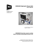
HCM-3E4-50 Hydraulic
Power Unit
User’s Manual
E.H. Wachs
600 Knightsbridge Parkway
Lincolnshire, IL 60069
www.ehwachs.com
E.H. Wachs Company Part No. 14-MAN-28
Copyright © 2011 E.H. Wachs. All rights reserved.
This manual may not be reproduced in whole or in part
without the written consent of E.H. Wachs.
Table of Contents
Table of Contents
Chapter 1: HCM-3E4-50 Hydraulic Power Unit . . . . . . . . . . . . . . . . . . . . . . . . . . . . . . . . . . . 1
Features and Specifications . . . . . . . . . . . . . . . . . . . . . . . . . . . . . . . . . . . . . . . . . . . . . . . . . . . . . . 1
Wiring Reference . . . . . . . . . . . . . . . . . . . . . . . . . . . . . . . . . . . . . . . . . . . . . . . . . . . . . . . . . . . . . . 3
Power Switch . . . . . . . . . . . . . . . . . . . . . . . . . . . . . . . . . . . . . . . . . . . . . . . . . . . . . . . . . . . . . . 3
Plug (Input) Wiring . . . . . . . . . . . . . . . . . . . . . . . . . . . . . . . . . . . . . . . . . . . . . . . . . . . . . . . . . 3
Switch and Fusebox Wiring . . . . . . . . . . . . . . . . . . . . . . . . . . . . . . . . . . . . . . . . . . . . . . . . . . . 3
Motor Wiring . . . . . . . . . . . . . . . . . . . . . . . . . . . . . . . . . . . . . . . . . . . . . . . . . . . . . . . . . . . . . . 4
Chapter 2: Safety . . . . . . . . . . . . . . . . . . . . . . . . . . . . . . . . . . . . . . . . . . . . . . . . . . . . . . . . . . . . . 5
Operator Safety . . . . . . . . . . . . . . . . . . . . . . . . . . . . . . . . . . . . . . . . . . . . . . . . . . . . . . . . . . . . . . . 5
Safety Symbols . . . . . . . . . . . . . . . . . . . . . . . . . . . . . . . . . . . . . . . . . . . . . . . . . . . . . . . . . . . . 6
Protective Equipment Requirements . . . . . . . . . . . . . . . . . . . . . . . . . . . . . . . . . . . . . . . . . . . . 7
Safety Procedures . . . . . . . . . . . . . . . . . . . . . . . . . . . . . . . . . . . . . . . . . . . . . . . . . . . . . . . . . . 7
Chapter 3: Operating Instructions . . . . . . . . . . . . . . . . . . . . . . . . . . . . . . . . . . . . . . . . . . . . . . 11
Hydraulic System . . . . . . . . . . . . . . . . . . . . . . . . . . . . . . . . . . . . . . . . . . . . . . . . . . . . . . . . . . . . . 11
Hydraulic Fluid Requirements . . . . . . . . . . . . . . . . . . . . . . . . . . . . . . . . . . . . . . . . . . . . . . . . 11
Tool Hose Recommendations . . . . . . . . . . . . . . . . . . . . . . . . . . . . . . . . . . . . . . . . . . . . . . . . 12
Operation . . . . . . . . . . . . . . . . . . . . . . . . . . . . . . . . . . . . . . . . . . . . . . . . . . . . . . . . . . . . . . . . . . . 13
Pre-Operation Checklist . . . . . . . . . . . . . . . . . . . . . . . . . . . . . . . . . . . . . . . . . . . . . . . . . . . . . 13
Starting the Power Unit . . . . . . . . . . . . . . . . . . . . . . . . . . . . . . . . . . . . . . . . . . . . . . . . . . . . . 14
Operating the Tool . . . . . . . . . . . . . . . . . . . . . . . . . . . . . . . . . . . . . . . . . . . . . . . . . . . . . . . . . 15
Chapter 4: Maintenance . . . . . . . . . . . . . . . . . . . . . . . . . . . . . . . . . . . . . . . . . . . . . . . . . . . . . . 17
Hydraulic System Maintenance . . . . . . . . . . . . . . . . . . . . . . . . . . . . . . . . . . . . . . . . . . . . . . . . . . 17
Motor Maintenance . . . . . . . . . . . . . . . . . . . . . . . . . . . . . . . . . . . . . . . . . . . . . . . . . . . . . . . . . . . 19
Troubleshooting . . . . . . . . . . . . . . . . . . . . . . . . . . . . . . . . . . . . . . . . . . . . . . . . . . . . . . . . . . . . . . 20
Chapter 5: Parts List and Assembly . . . . . . . . . . . . . . . . . . . . . . . . . . . . . . . . . . . . . . . . . . . . 23
Chapter 6: Ordering Information . . . . . . . . . . . . . . . . . . . . . . . . . . . . . . . . . . . . . . . . . . . . . . 27
Ordering Replacement Parts . . . . . . . . . . . . . . . . . . . . . . . . . . . . . . . . . . . . . . . . . . . . . . . . . . . . 27
Repair Information . . . . . . . . . . . . . . . . . . . . . . . . . . . . . . . . . . . . . . . . . . . . . . . . . . . . . . . . . . . . 27
Warranty Information . . . . . . . . . . . . . . . . . . . . . . . . . . . . . . . . . . . . . . . . . . . . . . . . . . . . . . . . . 28
Return Goods Address . . . . . . . . . . . . . . . . . . . . . . . . . . . . . . . . . . . . . . . . . . . . . . . . . . . . . . . . . 28
E.H. Wachs
Part No. 14-MAN-28, Rev. 0-0811
1
HCM-3E4-50 Hydraulic Power Unit
2
Part No. 14-MAN-28, Rev. 0-0811
E.H. Wachs
Chapter 1
HCM-3E4-50
Hydraulic Power Unit
The Wachs HCM-3E4-50 hydraulic power unit is an electric-powered unit providing 8 gpm flow at a maximum
pressure of 1500 psi (30 l/min at 103 bar). It is available in
either a standard or an explosion-proof configuration. The
explosion-proof version uses a motor and power panel
designed for safe operation in explosive environments.
The HCM-3E4-50 is designed to operate Type 1, Type 2, or
Type 3 open-center tools.
FEATURES AND SPECIFICATIONS
CHECK ITEMS IN BOLD
•
•
•
•
•
•
•
•
15 HP electric motor
440 V, 50 Hz power requirement.
Enclosed hydraulic system with self-contained reservoir and filtration.
Sound-suppression lining.
Enclosed, high-capacity cooling system with shaftmounted air-to-oil cooler and suction fan; meets or
exceeds HTMA specifications.
Hydraulic oil level sight gauge.
HTMA quick disconnect couplers.
Cart design with collapsible handles and large diameter
tires.
Table 1 and the following figures describe the 3E3 electric
power unit.
E.H. Wachs
Part No. 14-MAN-28, Rev. 0-0811
1
HCM-3E4-50 Hydraulic Power Unit
Table 1: HCM-3E4-50 Specifications
Hydraulic system
Open center
Frame type
2-wheel mobile unit
Electrical
415-440 V, 50 Hz, 3 phase
Fuse panel
30 A
Wiring
10 gauge (5 mm2)
Motor
15 HP, 440 V, 3 phase
Oil cooler
Air to oil with independent fan
Filtration
10 micron return
Hydraulic oil capacity
7.0 gallons (25.6 liters)
Rated flow (no pressure)
8 gpm (30 l/min)
Rated flow @ 1500 psi (103 bar)
15 gpm (56 l/min)
Rated (relief) pressure
1500 psi (103 bar)
Dimensions (L x W x H)
38.5” x 26” x 40”
(978 x 660 x 1016 mm)
Weight
500 lb (227 kg)
Tank (return) port
Pressure port
On/off switch
Flow control knob
Figure 1-1. The photo shows the 3E4-50 electric
power unit.
E.H. Wachs
2
WIRING REFERENCE
Wachs hydraulic power units are prewired at the factory.
This page describes wiring of the HCM-3E4-50 in case you
need to perform service on the unit. Refer to the electrical
specifications in Table 1.
Power Switch
The power switch is on the front of the electrical control
box. Turn the switch clockwise to turn the unit on. Turn the
switch counter-clockwise to turn the unit off.
WARNING
All electrical work should be
performed by a qualified electrician. Disconnect main electrical power to the unit before
removing covers. Disconnect
hydraulic circuit before performing service.
OFF
ON
Plug (Input) Wiring
The photo at the right shows the input power cable. The
green wire is ground. The other wires (black, white, and
red) are hot.
After connecting the cable to input power, “bump” the
motor on and off to check the direction it is rotating. A label
on the motor (shown at right) indicates the motor rotation
direction. If the motor is rotating the wrong direction, flip
any 2 of the “hot” power input wires to reverse the direction.
Switch and Fusebox Wiring
Ground (green)
Motor should turn clockwise
The photos below show the wiring of the switch and fusebox. Make sure fuses are 30 amps.
E.H. Wachs
Part No. 14-MAN-28, Rev. 0-0811
3
HCM-3E4-50 Hydraulic Power Unit
To fusebox
Power input
To motor
Motor Wiring
The motor on the HCM-3E4-50 is prewired at the factory
for high voltage (440 V) operation, as shown on the wiring
connection label on the motor. No other service is required.
Voltage of units in the field cannot be changed with the supplied components. Contact factory service at E.H. Wachs if
this is required.
4
Part No. 14-MAN-28, Rev. 0-0811
E.H. Wachs
Chapter 2, Safety
Chapter 2
Safety
E.H. Wachs takes great pride in designing and manufacturing safe, high-quality products. We make user safety a top
priority in the design of all our products.
In This Chapter
OPERATOR SAFETY
Read this chapter carefully before operating the hydraulic
power unit. It contains important safety instructions and
recommendations.
OPERATOR SAFETY
Follow these guidelines for safe operation of the equipment.
•
•
•
•
READ THE OPERATING MANUAL. Make sure
you understand all setup and operating instructions
before you begin.
INSPECT MACHINE AND ACCESSORIES.
Before starting the machine, look for loose bolts or
nuts, leaking lubricant, rusted components, and any
other physical conditions that may affect operation.
Properly maintaining the machine can greatly decrease
the chances for injury.
ALWAYS READ PLACARDS AND LABELS. Make
sure all placards, labels, and stickers are clearly legible
and in good condition. You can purchase replacement
labels from E.H. Wachs Company.
KEEP CLEAR OF MOVING PARTS. Keep hands,
arms, and fingers clear of all rotating or moving parts.
E.H. Wachs
Part No. 14-MAN-28, Rev. 0-0811
Look for this symbol throughout the
manual. It indicates
a personal injury
hazard.
5
HCM-3E4-50 Hydraulic Power Unit
•
•
Always turn machine off before doing any adjustments
or service.
SECURE LOOSE CLOTHING AND JEWELRY.
Secure or remove loose-fitting clothing and jewelry, and
securely bind long hair, to prevent them from getting
caught in moving parts of the machine.
KEEP WORK AREA CLEAR. Keep all clutter and
nonessential materials out of the work area. Only people
directly involved with the work being performed should
have access to the area.
Safety Symbols
This icon is displayed with any safety alert that indicates a
personal injury hazard.
WARNING
This safety alert indicates a potentially hazardous situation
that, if not avoided, could result in death or serious injury.
CAUTION
This safety alert, with the personal injury hazard symbol,
indicates a potentially hazardous situation that, if not
avoided, could result in minor or moderate injury.
NOTICE
This alert indicates a situation that, if not avoided, will
result in damage to the equipment.
6
Part No. 14-MAN-28, Rev. 0-0811
E.H. Wachs
Chapter 2, Safety: Operator Safety
IMPORTANT
This alert indicates a situation that, if not avoided, may
result in damage to the equipment.
Protective Equipment Requirements
WARNING
Always wear impact resistant eye protection while operating or working near
this equipment.
For additional information on eye and face protection, refer
to Federal OSHA regulations, 29 Code of Federal Regulations, Section 1910.133., Eye and Face Protection and
American National Standards Institute, ANSI Z87.1, Occupational and Educational Eye and Face Protection. Z87.1 is
available from the American National Standards Institute,
Inc., 1430 Broadway, New York, NY 10018.
CAUTION
Personal hearing protection is recommended when operating or working near
this equipment.
Hearing protectors are required in high noise areas, 85 dBA
or greater. The operation of other tools and equipment in the
area, reflective surfaces, process noises, and resonant structures can increase the noise level in the area. For additional
information on hearing protection, refer to Federal OSHA
regulations, 29 Code of Federal Regulations, Section
1910.95, Occupational Noise Exposure and ANSI S12.6
Hearing Protectors.
Safety Procedures
All safety requirements listed below are those generally
applicable to hydraulically-powered machinery but are not
intended to be an all-inclusive list. They are intended as
guidelines only and will assist in avoiding risk of injury
when followed by qualified, experienced personnel. These
E.H. Wachs
Part No. 14-MAN-28, Rev. 0-0811
7
HCM-3E4-50 Hydraulic Power Unit
precautions should be included in the comprehensive safety
program for the particular machinery, equipment, plant or
process and overseen by personnel capable of analyzing any
hazards associated with operating and maintaining the
equipment.
WARNING
Many types of
machinery have
parts that may
start moving as soon as the
hydraulic circuit is filled and
pressurized. This could result
in injury to personnel or damage to machinery.
1. Return all movable parts of the machinery being operated to their normal startup condition, if possible,
before starting unit.
2. Be sure all personnel, product, etc. are clear of
machinery before starting hydraulic unit.
3. Check to make sure any hydraulic connections which
may have been removed, replaced or disconnected
during shut down have been reconnected securely
before starting hydraulic unit.
4. Before starting the unit, perform all equipment checks
described at the beginning of the operating instructions.
5. If there are tools or machinery being operated by the
HPU that may move when hydraulic flow or pressure
are turned off or turned on, block or lock these parts in
position before shutting down the hydraulic unit.
WARNING
Make sure all personnel are clear
from the machinery being operated before
shutting down the HPU.
6. Shut down the hydraulic unit and relieve pressure
from all pressurized accumulators, actuators and lines
before removing, tearing down or performing maintenance on any remotely-located actuators, hoses, filters, valves, piping, etc.
7. Any personnel observing or working on or adjacent to
hydraulically-powered equipment must never place
themselves in a location or position that could produce
an injury in the event of:
•
•
•
•
8
a hydraulic line failure either with the unit running or
shut down;
pump or motor failure or;
pin-hole leaks in hoses or fittings;
movement of machine components during normal operation or resulting from a component malfunction or failure.
Part No. 14-MAN-28, Rev. 0-0811
E.H. Wachs
Chapter 2, Safety: Operator Safety
8. Do not inspect hoses and fittings for leaks using your
bare hands. A pin-hole leak can inject hydraulic fluid
through the skin, with the potential for serious injury.
9. Avoid locating equipment in any environment for
which it was not designed and which may create a
dangerous operating condition such as an explosive
atmosphere (e.g., gas, dust), high heat (e.g., molten
metal, furnace), chemicals, extreme moisture, etc.
WARNING
The injection of
hydraulic fluid
under the skin can
cause serious injury and
even result in death. If an
injection injury occurs, seek
medical treatment immediately.
10. Avoid bodily contact with hydraulic fluids. Some
hydraulic fluids may irritate or injure the eyes and
skin. Check with your fluid suppliers to obtain this
information.
11. Use only E.H. Wachs parts and materials when servicing the equipment. Substitute parts or materials could
produce a hazardous operating condition.
12. When piping your equipment, use only materials of
adequate size and strength to suit the flows and pressures of the system. Consider all safety factors when
selecting the strength of materials to allow for shock
and over-pressure conditions which could occur.
E.H. Wachs
Part No. 14-MAN-28, Rev. 0-0811
9
HCM-3E4-50 Hydraulic Power Unit
10
Part No. 14-MAN-28, Rev. 0-0811
E.H. Wachs
Chapter 3, Operating Instructions
Chapter 3
Operating
Instructions
In This Chapter
HYDRAULIC SYSTEM
HYDRAULIC SYSTEM
OPERATION
The hydraulic system consists of a hydraulic fluid reservoir,
filter assembly, single pump, and flow controls. The filter is
a spin-on element for easy replacement. The filter housing
has a pressure bypass valve to divert fluid directly to the
tank in the event of a restricted filter.
Refer to the specifications table in Chapter 1 for capabilities of the hydraulic system and pump.
Pressure hoses from the pump are connected directly to a
control module, which contains a relief valve, a flow control valve, and pressure and return ports. Optional control
modules may contain additional valves and ports.
Hydraulic Fluid Requirements
The power unit is shipped from the factory empty. Oils
meeting the specifications listed below will provide all-season operation if normal maintenance is performed.
The following fluids are recommended by E.H. Wachs.
These fluids work well over a wide temperature range at
start-up, allow moisture to settle out, and resist biological
growth likely in cool operating hydraulic circuits. Other
fluids that meet or exceed their specifications may also be
used.
E.H. Wachs
Part No. 14-MAN-28, Rev. 0-0811
11
HCM-3E4-50 Hydraulic Power Unit
•
•
•
•
•
Mobil DTE 24
Mobil SCH 524
Mobil DTE 10 Excel 32
Shell Tellus T-32
Texaco Rando
Table 1: Viscosity
Temperature
Viscosity
50° F (10° C)
450 SSU max. (95 centistrokes, C.S.)
100° F (38° C)
130-220 SSU (27-42 C.S.)
140° F (60° C)
85 SSU min. (16.5 C.S. min)
Table 2: Hydraulic Fluid Properties
Property
Specification
Pour point
-10° F (-23° C) min. (for cold startup)
Viscosity index
(ASTM D 2220) 140 min.
Demulsibility
(ASTM D 1401) 30 minutes max.
Flash point
(ASTM D 92) 340° F (171° C) min
Rust inhibition
(ASTM D 665 A&B) Pass
Oxidation
(ASTM D 943) 1000 hours min.
Pump wear test
(ASTM D 2882) 60 mg max.
Tool Hose Recommendations
The following table lists recommended hydraulic hoses for
a variety of applications.
12
Part No. 14-MAN-28, Rev. 0-0811
E.H. Wachs
Chapter 3, Operating Instructions: Operation
Table 3: Hydraulic Hose Recommendations
OPERATION
Pre-Operation Checklist
•
•
•
•
•
•
Check the oil level in the hydraulic reservoir, and add oil
if necessary.
Connect the unit according the wiring instructions in
Chapter 1.
Check all hydraulic hoses for damage.
Check all fittings and couplings to make sure they are
tightly connected.
Make sure the front of the motor is free of leaves, dirt,
or other debris that may inhibit cooling or create a fire
hazard.
Check hydraulic connections as described in the following figure.
1 = H.T.M.A. 3/8” male quick acting coupler with 1/2”
NPT thread.
2 = H.T.M.A. 3/8” female quick acting coupler with
1/2” NPT thread. (At the tool this may be H.T.M.A. 3/8”
female quick acting coupler with 3/8” NPT thread.
3 = H.T.M.A. 3/8” quick acting coupler with 1/2” NPT
E.H. Wachs
Part No. 14-MAN-28, Rev. 0-0811
13
HCM-3E4-50 Hydraulic Power Unit
thread.
4 = H.T.M.A. 3/8” male quick acting coupler with
1/2” NPT thread. (At the tool this may be H.T.M.A. 3/8”
male quick acting coupler with 3/8” NPT thread.
A = Refer to Table 3 for hose recommendations.
B = Use adapters with threads that match the tool connectors.
Figure 3-1. The diagram illustrates the hydraulic
connectors.
Starting the Power Unit
1. Make sure the flow control circuit is set at 0 or off.
2. Make sure the tool is off or deactivated.
3. Connect the hydraulic hoses to the couplers on the
power unit.
4. Connect the hydraulic hoses to the couplers on the
tool.
14
Part No. 14-MAN-28, Rev. 0-0811
E.H. Wachs
Chapter 3, Operating Instructions: Operation
5. Plug the power unit into the power source.
6. Turn the motor switch ON.
7. Allow the power unit to run without activating the tool
until the hydraulic circuit warms up.
Operating the Tool
1. With the power unit running, turn the hydraulic circuit
to the ON position, or turn the flow setting control to
enable flow.
2. To pause or shut off the tool, return the circuit control
to the OFF position, or set the flow control to 0.
3. When finished, turn the power unit switch to the OFF
position.
E.H. Wachs
Part No. 14-MAN-28, Rev. 0-0811
15
HCM-3E4-50 Hydraulic Power Unit
16
Part No. 14-MAN-28, Rev. 0-0811
E.H. Wachs
Chapter 4, Maintenance
Chapter 4
Maintenance
IMPORTANT: Use on genuine E.H. Wachs parts or equivalent. Using replacement parts that are not of equivalent
quality may damage the hydraulic power unit.
In This Chapter
HYDRAULIC SYSTEM
MAINTENANCE
MOTOR MAINTENANCE
TROUBLESHOOTING
HYDRAULIC SYSTEM MAINTENANCE
Observe the following for maximum performance and service life from the hydraulic system. See Table 1 at the end
of this section for maintenance intervals.
•
•
•
•
•
Use the correct hydraulic fluid at all times.
Keep the hydraulic system and fluids clean at all times.
Keep water out of the fluid.
Keep air out of the lines. Air is indicated by the hydraulic system overheating and foam at the hydraulic tank
breather. Tighten all suction line fittings and clamps.
Hydraulic system wear is indicated by increased heat
during tool operation, reduced tool performance, and
eventual system breakdown.
1. Remove condensed moisture from the hydraulic fluid.
• Condensation is a frequent problem with cool
mobile hydraulic circuits. This condition occurs in
moist or cold climates when warm air in the reservoir tank draws moisture from the cooler outside
air. Water will then accumulate in the tank.
• Check the suction hose from the hydraulic tank to
the pump inlet to make sure it is not kinked and that
E.H. Wachs
Part No. 14-MAN-28, Rev. 0-0811
17
HCM-3E4-50 Hydraulic Power Unit
the clamps are secure. This will reduce the risk of
pump cavitation and sucking air into the system. All
pump fittings must be tight.
• Approximately once each week (less often in hot,
arid climates), take a small sample from the bottom
of the hydraulic tank by removing the 1/2” NPT
drain plug. If clear water appears, drain tank until
clean oil is flowing. If fluid is milky, allow it to settle for about 48 hours before draining.
2. Check hydraulic fittings and lines. Check for leaks,
loose fittings, etc. throughout the entire hydraulic circuit.
3. Change the hydraulic filter.
• To keep contaminants out of the hydraulic fluid and
extend filter life, always connect the hose ends
together when the tool is disconnected, and wipe off
the connectors each time before connecting them.
4. Fill the hydraulic tank.
• Remove the filter cap at the top center of the tank to
fill it. The tank is full when oil appears in the perforated basket at the bottom of the filler pipe.
Table 1: Hydraulic Maintenance Schedule
Service Item
Service Interval
Check fluid level
Each use or 8 hours
Check oil and filter
Every year or 300 hours
Remove condensation from fluid
Every 3 months or 50 hours
Inspect hydraulic system for
leaks
Each use or 8 hours
Check pump coupling (replace if
necessary)
Every 2 years*
Check internal hose assemblies
(replace if necessary)
Every 2 years*
Test hydraulic flows and pressures (service as required)
Every 2 years*
* These items should be serviced by a qualified hydraulics technician.
18
Part No. 14-MAN-28, Rev. 0-0811
E.H. Wachs
Chapter 4, Maintenance: Motor Maintenance
MOTOR MAINTENANCE
The sealed motor bearings are pre-greased at the factory for
normal bearing life.
1. On motors supplied with a grease fitting, apply grease
with a grease gun according to the schedule in Table 2
at the end of this section.
• On NEMA 215 and smaller frames, use 1 to 2 full
strokes of the grease gun.
• On NEMA 254 through NEMA 365 frames, use 2 to
3 strokes.
• On NEMA 404 and larger frames, use 3 to 4 strokes.
2. On motors with drain plugs, remove the grease drain
plug and run the motor for 20 minutes. Replace the
drain plug.
3. On motors equipped with slotted head grease screws,
remove the screw and apply grease tube to the hole.
• On NEMA 215 and smaller frames, insert a 2 to 3
inch length grease string.
• On NEMA 254 and larger frames, insert a 3 to 5
inch length grease string.
Table 2: Motor Maintenance Schedule
Relube Interval
Usage Level
42 to 215T
Frame
254 to 326T
Frame
364 to 447T
Frame
5000 hours
5 years
3 years
1 year
Continuous normal
application
2 years
1 year
9 months
Seasonal service (motor
is idle for 6 months or
more)
1 year
(beginning
of season)
1 year
1 year
Continuous in wet or dirty
environment
E.H. Wachs
6 months
Part No. 14-MAN-28, Rev. 0-0811
19
HCM-3E4-50 Hydraulic Power Unit
TROUBLESHOOTING
Table 3: Power Unit Troubleshooting
Problem
Cause
Remedy
Motor will not start
Line trouble (such as single
phasing at the starter).
Check power source for overloads, fuses,
controls, etc.
Excessive humming
High voltage.
Check input line connection.
Overload. Compare actual amps
(measured) with nameplate ratings.
Single phasing.
Locate and remove source of excessive
friction in motor or load.
Reduce load or replace motor with one of
greater capacity.
Check current at all phases (should be
approximately equal) and correct problem
when isolated.
Check external cooling fan to be sure air is
moving properly.
Improper ventilation.
Check motor for dirt build-up and clean
motor.
Unbalanced voltage.
Motor overheating
Check voltage at all phases (should be
approximately equal) and correct problem
when isolated.
Check air gap clearance and bearings.
Rotor rubbing on stator.
Tighten “through bolts”.
Bearing overheating
20
Over voltage or under voltage.
Check input voltage at each phase to
motor.
Open stator winding.
Check stator resistance at all three
phases for balance.
Grounded wiring.
Perform dialectric test and repair as
required.
Improper connections.
Inspect all electric connections for proper
termination, clearance, mechanical
strength, and electrical continuity. Refer to
motor lead connection diagram on motor
plate.
Excessive grease in bearing.
Remove grease until cavity is approximately 3/4 filled.
Insufficient grease in bearing.
Add grease until cavity is approximately
3/4 filled.
Dirt in bearing.
Clean bearing cavity and bearings.
Repack with correct grease until cavity is
approximately 3/4 filled.
Part No. 14-MAN-28, Rev. 0-0811
E.H. Wachs
Chapter 4, Maintenance: Troubleshooting
Table 3: Power Unit Troubleshooting
Problem
Vibration
Noise
Cause
Remedy
Rubbing between rotating parts
and stationary parts.
Isolate and eliminate cause of rubbing.
Rotor out of balance.
Have rotor balance checked or repaired.
Resonance.
Tune system or contact E.H. Wachs service for assistance.
Foreign material in air gap or
ventilation openings.
Remove rotor and foreign material. Reinstall rotor.
Check insulation integrity.
Clean ventilation openings.
Growling or whining
Motor runs but hydraulic circuit
will not drive tools
Bad bearings.
Replace bearings. Clean all grease from
cavity and new bearing. repack with correct grease until cavity is approximately
3/4 filled.
Tool not connected to power unit.
Connect tool. Check coupler.
Hydraulic fluid reservoir low.
Check and fill as required.
Tool hoses blocked.
Remove obstruction.
Tool hoses incorrectly connected
to circuit fittings.
Check that tool hose goes from top port
and from tool return or out port to lower
port; both ports on same side of the manifold.
Relief valve(s) stuck open.
Adjust or replace valve(s).
Tool is defective.
Repair as necessary.
Hoses too small.
Increase hose diameter. (Refer to hose
specification table in Chapter 3.)
Improper fluid.
Replace fluid.
Cooler clogged, blocked air flow.
Clean cooler and straighten fins as necessary.
Hydraulic pump damaged.
Replace pump.
Flow control valves or priority
valves have been added to circuit.
Some rotary tools must have flow controls.
Adjust flow to match tool gpm to avoid
forcing excess flow over relief.
Closed center tools in use.
Use only open center tools.
Tool runs too hot
E.H. Wachs
Part No. 14-MAN-28, Rev. 0-0811
21
HCM-3E4-50 Hydraulic Power Unit
22
Part No. 14-MAN-28, Rev. 0-0811
E.H. Wachs
Chapter 5
Parts List and
Assembly
The following table lists the parts for the HCM-3E4-50
power unit. See the drawing after the list for assembly and
parts identification.
ITEM
DESCRIPTION
QTY
1
FILTER COMPLETE
FILTER ELEMENT REPLACEMENT
1
2
NUT JAM,
9
3
BOLT, 1/4nc X 3/4
19
4
BOLT, 1/4nc X 2 ¼
2
5
FITTING, #6901-10-8
1
6
PLUG, 1/2 MAGNETIC
1
7
CLAMP HOSE
2
8
NUT, 3/8 nc
2
9
NUT ¼ nc
23
10
NUT ¼ nc NYLOCK
2
11
LOCK WASHER 3/8
2
12
FITTING, 1/2 NIPPLE #5404-0808
2
13
PIN, COTTER 1/8 X 1 1/4
2
14
CLAMP,
4
E.H. Wachs
.750
Part No. 14-MAN-28, Rev. 0-0811
23
HCM-3E4-50 Hydraulic Power Unit
E.H. Wachs
15
NUT, 5/16nc
6
16
WASHER, 1/4 FLAT PLATED
12
17
HOSE, -16 X 5.5
1
18
VALVE, RELIEF
1
19
WASHER, LOCK 5/16
6
20
WASHER FLAT 5/16
2
21
COOLER
1
22
BOLT, 1/4nc X ½
4
23
FITTING #4501-1212
3
24
WASHER, LOCK 1/2
4
25
NUT, 1/2 nc
4
26
FITTING #2047-8-8S
1
27
WASHER, LOCK 10-32 BOLT
4
28
BOLT 1/4nc X 3/4 SOCKET HEAD
4
29
GAUGE, SIGHT
1
30
BOLT 3/8nc X 1 ¼
2
31
BOLT 1/2nc X 2
4
32
HOSE, RETURN -12 X 40
1
33
CLAMP, HOSE
5
34
MANIFOLD
1
35
FITTING #20350-12-8
1
36
BOLT 5/16nc X 3/4
6
37
BOLT 1/4ncX 1 ½
4
38
FOOT
2
39
BOLT 1/4ncX1 SK.HD. CAP.SCREW
3
40
FITTING 4604-16-12
1
41
GRIP HANDLE
2
42
SPACER COOLER
4
43
COUPLER HYDRAULIC FEMALE
1
44
COUPLER HYDRAULIC MALE
1
45
FAN
1
46
HOSE PRESSURE
1
24
47
SUPPORT PUMP
1
48
GRAPHIC SET E-10 PortaCo
1
49
PIN SPRING
2
50
HANDLE
2
51
HOSE RETURN
1
52
VALVE CONTROL
1
53
WHEEL 14"
2
54
PUMP HYDRAULIC
1
55
TANK/FRAME
1
56
GUARD FAN LOWER
1
57
GUARD FAN UPPER
1
58
GRILL
1
59
COUPLER PUMP
1
60
AXLE
1
61
SPACER WHEEL
2
62
MOUNT HANDLE
2
63
MOTOR ELECTRIC 15 HP
1
64
CAP FILLER
1
65
WASHER LOCK 1/4
38
E.H. Wachs
Part No. 14-MAN-28, Rev. 0-0811
25
HCM-3E4-50 Hydraulic Power Unit
26
E.H. Wachs
Chapter 6, Ordering Information
Chapter 6
Ordering Information
In This Chapter
To place an order, request service, or get more detailed
information on any E.H. Wachs products, call us at one of
the following numbers:
ORDERING REPLACEMENT
PARTS
REPAIR INFORMATION
U.S.
800-323-8185
International: 847-537-8800
WARRANTY INFORMATION
RETURN GOODS ADDRESS
You can also visit our Web site at:
www.ehwachs.com
ORDERING REPLACEMENT PARTS
When ordering parts, refer to the drawings and parts lists in
Chapter 8. Please provide the part description and part
number for all parts you are ordering.
REPAIR INFORMATION
Please call us for an authorization number before returning
any equipment for repair or factory service. We will advise
you of shipping and handling. When you send the equipment, please include the following information:
• Your name/company name
• Your address
• Your phone number
• A description of the problem or the work to be done.
E.H. Wachs
Part No. 60-MAN-08, Rev. 0-0311
27
Low Clearance Split Frame, Models 1824-4248
Before we perform any repair, we will estimate the work
and inform you of the cost and the time to complete it.
WARRANTY INFORMATION
Enclosed with the manual is a warranty card. Please fill out
the registration card and return to E.H. Wachs. Retain the
owner’s registration record and warranty card for your
information.
RETURN GOODS ADDRESS
Return equipment for repair to the following address.
E.H. Wachs
600 Knightsbridge Parkway
Lincolnshire, Illinois 60069 USA
28
Part No. 60-MAN-08, Rev. 0-0311
E.H. Wachs
600 Knightsbridge Parkway • Lincolnshire, IL 60069
847-537-8800 • www.ehwachs.com