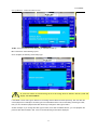
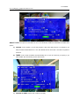
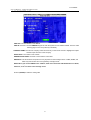
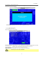
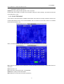
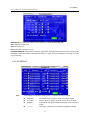
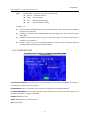
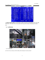
1
User Manual
Ness IQ-MDVR-4
GUI
Mobile Digital Video Recorder
User Manual
Ness IQ-MDVR-4 – Mobile Black Box Recorder.
NOTICE
The information in this manual was current when published. The manufacturer reserves the right to revise and
improve its products. All specifications are therefore subject to change without any notice.
The purpose of this manual is to aid the user for the operation for our IQ-MDVR (especially for GUI setting). The
user should have a basic understanding of computer operation and basic knowledge of how to connect
peripherals and make some settings.
2
User Manual
Ness IQ-MDVR-4 – Mobile Black Box Recorder.
1 PRODUCT CHARACTERISTICS AND OVERVIEW .......................................................................... 5
1.1 PRODUCT OVERVIEW............................................................................................................... 5
1.1.1 VIDEO/AUDIO FERATURES AND CAPABILITIES...................................................... 5
1.1.2 REMOTE CONNECTION CAPABILITIES ..................................................................... 5
1.1.3 ACCESSORY MODULES FOR MDVR.......................................................................... 5
2 HANDHELD IR REMOTE CONTROL .................................................................................................. 6
2.1 NUMERIC KEYPAD ..................................................................................................................... 7
2.2 SETUP MENU NAVIGATION...................................................................................................... 7
2.3 OTHER KEYS FUNCITONS ..................................................................................................... 7
2.4 PTZ FUNCTION KEYS ................................................................................................................ 8
3 MENU TREE............................................................................................................................................. 9
4 SYSTEM START UP ............................................................................................................................. 10
5 SEARCH and PLAYBACK VIDEO FILE ............................................................................................. 12
5.1 ALL FILES .................................................................................................................................... 12
5.2 EVENT FILES ............................................................................................................................. 15
6 SETUP..................................................................................................................................................... 17
6.1 SYSTEM ...................................................................................................................................... 17
6.1.1 DATA/TIME ....................................................................................................................... 18
6.1.2 GENERAL ........................................................................................................................ 19
6.1.3 REGISTER INFO ............................................................................................................ 21
6.1.4 FORMAT ........................................................................................................................... 22
6.1.5 UPGRADE ........................................................................................................................ 22
6.1.6 USER SECURITY ........................................................................................................... 24
6.1.7 CONFIG ............................................................................................................................ 26
6.1.8 SYSTEM LOG.................................................................................................................. 26
6.1.9 GEO-FENCING ............................................................................................................... 27
6.2 RECORD ..................................................................................................................................... 27
6.2.1 OPTIONS ......................................................................................................................... 28
6.2.2 OSD OVERLAY ............................................................................................................... 30
6.2.3 CAMERA SETTING ........................................................................................................ 32
6.2.4 RECORD SETTINGS ..................................................................................................... 32
6.2.5 SUB-STREAMING .......................................................................................................... 33
6.2.6 SCHEDULE ...................................................................................................................... 34
6.2.7 OTHER SETTING ........................................................................................................... 35
6.3 NETWORK .................................................................................................................................. 36
6.3.1 SERVER ........................................................................................................................... 36
6.3.2 LOCAL NETWORK ......................................................................................................... 37
6.3.3 WIFI SETUP..................................................................................................................... 38
6.3.4 MOBILE NETWORK ....................................................................................................... 39
6.4 EVENT ......................................................................................................................................... 41
6.4.1 SENSOR........................................................................................................................... 42
6.4.2 SENSOR OUTPUT ......................................................................................................... 43
6.4.3 SPEED .............................................................................................................................. 44
3
User Manual
Ness IQ-MDVR-4 – Mobile Black Box Recorder.
6.4.4 ACCELERATION ............................................................................................................. 45
6.4.5 TEMPERATURE .............................................................................................................. 46
6.4.6 CAMERA .......................................................................................................................... 46
6.4.7 VOLTAGE ......................................................................................................................... 47
6.5 PERIPHERAL ............................................................................................................................. 48
6.5.1 PTZ .................................................................................................................................... 48
6.5.2 EXT.COM SETUP ........................................................................................................... 49
7 INFORMATION ...................................................................................................................................... 50
7.1.1 SYSTEM ........................................................................................................................... 50
7.1.2 HISTORY .......................................................................................................................... 51
7.1.3 MODULES ........................................................................................................................ 52
4
User Manual
Ness IQ-MDVR-4 – Mobile Black Box Recorder.
1 PRODUCT CHARACTERISTICS AND OVERVIEW
1.1
PRODUCT OVERVIEW
The Ness IQ-MDVR-4 is a cost-effective and functional Mobile Digital Video Recorder specially designed for
vehicle surveillance and remote monitoring, combined with high-speed processor and embedded operating
system. The advanced H.264 video compression and decompression, GPS location make it to be a very powerful
and perfect solution for vehicles.
1.1.1 VIDEO/AUDIO FERATURES AND CAPABILITIES
4 channels for video and audio inputs, 2 channel real-time D1, 4CH D1 at 12fps/15fps continuous or
priority video recording and live view display.
Semi-transparent GUI makes setting for GUI and live display synchronously.
Special file system NVRFSTM is very good for improving the security level of data, providing
self-recovery function, self-check, self-backup for certain critical data and avoiding data fragment that
affect system efficiency.
Watermark prevents any modification in recorded file, which is part of the law enforcement.
Better Compression rate at H.264 (50% less than MPEG4).Enhance recording storage rate in most
efficiency way.
4 channels for high-fidelity, digitally recorded, synchronized audio matched to 4 video channels
User friendly criteria to playback the events associated video only.
Dual-Stream for wireless transmission depends on wide or narrow bandwidth.
User-selectable settings for quality and audio record enable/disable for each video channel.
12v power supply for multiple devices such as cameras, sensors, relays and any other accessories.
Selectable frame rate with event-triggered burst recording speeds up to 30FPS/camera.
Multiple alarm inputs with selectable pre-alarm and post-alarm record timings.
1.1.2 REMOTE CONNECTION CAPABILITIES
Handheld Infra-Red controller with OSD for quick access to recorded video and settings menu.
PC-Based Client software for live viewing, playback video, playback events video and download
capabilities
Support CMS (Central Management System) for remote monitoring by 3G (HSDPA or EVDO) and WIFI,
PAS (Playback Analysis Software) for video playback, meta-data analysis.
1.1.3 ACCESSORY MODULES FOR MDVR
Video Interface Module including GPS location and speed.
Control panel for driver’s simply operation.
Vehicle Motion Manager includes 3-axis Inertia Sensor to determine video-matched motion events.
Wireless module GPRS /3G, WIFI for transferring data to CMS server for remote monitoring.
5
User Manual
Ness IQ-MDVR-4 – Mobile Black Box Recorder.
2 HANDHELD IR REMOTE CONTROL
Numeric
Input Keys
Use the numbers to input
Values in the system setup
Screen or switch through the channels
in live view.
Navigation
Arrows
Use the ARROW keys to move between
selections, input fields and icons.
Press ENTER to select
And EXIT to return. Next and previous is also
used to increase or decrease volume when at live
or search screens.
Each MDVR includes a handheld Infra-Red (IR) controller that allows the user to transmit commands
to recording module and display on screen control menu
6
User Manual
Ness IQ-MDVR-4 – Mobile Black Box Recorder.
2.1
NUMERIC KEYPAD
[0-9] keys: During setup, number keys are used to input number values.
In live view window, you can press 1, 2, 3 and 4 to switch to full screen, and press 0 to switch to
quad view.
During full screen view of each camera, you can press
key to adjust contrast, luminance,
color and saturation, and then press + and - to make the adjustments. Pressing
navigate through the color adjustment options.
2.2
SETUP MENU NAVIGATION
▲, ▼: Up, down directional keys: Move selection up and down in setup menu.
►, ◄: Left, Right directional keys: Move cursor left or right in setup menu.
[ENTER] key: During setup, select and save the settings
2.3
OTHER KEYS FUNCITONS
You can press LOGIN / LOCK or SETUP key to enter the GUI to setup. If
LOGIN/ LOCK
password enabled, you have to input default Admin password:
88888888.
To reset the MDVR in to sleep mode (You can press power button again
POWER
to let MDVR start up when it in sleep mode).
Switch full screen of one channel to quad view.
Brightness, contrast, color adjustment for per channel. Use [+] [-] button
to change the values. You have to adjust the values for each channel
individually.
SETUP
Login GUI to setup the parameters.
EXIT
Return to the previous menu.
Used to stop the recording manually. Only valid when you setup the
Stop
record mode as manual.
Used to start the recording manually. Only valid when you setup the
Record
record mode as manual.
Freezes playback to a single frame and can advance one frame at a
PAUSE/STEP
time. To advance the frame press Pause / Step to move frame by frame.
▐►
Press EXIT to return to normal playback speed.
PLAY
►
SLOW
GOTO
Starts/Resumes playback from any other mode (FF, RR, Frame by
Frame etc).
Reduces playback speed to 1/2, 1/4, 1/8 modes. Press PLAY to return to
normal playback speed.
Quick search mode when you playback the record file in MDVR. Press
7
will
User Manual
Ness IQ-MDVR-4 – Mobile Black Box Recorder.
GOTO button and input the desired time, and the select SURE to jump to
the specific time you want to playback.
NEXT
Increase volume while playback (if audio is recorded).
PREV
Decrease volume while playback (if audio is recorded).
REW
FWD
Rewinds the video while playback. X2 and X 4 modes available.
Fast forward the video while playback. X2 and X4 modes available.
CF
No use at present.
[F1]
Export all the event record files of the day to USB by press F1 key.
[F2],[F3],[F4]
Reserved for future use.
2.4
PTZ FUNCTION KEYS
While connect with PTZ camera and using the RS485 in DB26, following commands can control with
PTZ camera with following function:
[ZOOM IN +], [ZOOM OUT -]
ZOOM IN/OUT
[IRIS +], [IRIS-]
Brightness control
[FOCUS +], [FOCUS -]
Focus control
PTZ
Enable the PTZ function
AUTO
Auto run with the PTZ pattern
PRESET
Preset default position
RECALL
Recall the position that you have setup.
BRUSH
Brush the glass screen
Check battery in place of remote controller since no battery in the standard package
8
User Manual
Ness IQ-MDVR-4 – Mobile Black Box Recorder.
3 MENU TREE
Menu structure tree
9
User Manual
Ness IQ-MDVR-4 – Mobile Black Box Recorder.
4 SYSTEM START UP
Install the HDD/SD card first and then lock it in front panel. (Refer to HDD Installation Instructions of
how to install the HDD into the HDD Caddy)
For testing, just connect the red wire and yellow wires together to Power + (8~36V DC) and connect the
black wire to GND. However when installed in a vehicle, please connect red wire to power +, yellow
wire to Ignition, black GND wire to power -.
SYSTEM LOGIN FOR SETUP
MDVR GUI is semi-transparent which allows you to see the live view when you make GUI
configurations
10
User Manual
Ness IQ-MDVR-4 – Mobile Black Box Recorder.
•
When Password is set to ‘disable’, press the SETUP key on the handheld controller to access the setup
menu directly;
•
When Password is set to ‘enable’, press LOGIN/LOCK OR ENTER key on the handheld controller for the
setup menu to appear:
UNIT ID: The unit ID of MDVR. You enter the ID setting in the GUI and then the numbers will display on screen
automatically.
PASSWORD: Enter the admin password or user password.
User default password is 22222222, and Admin password is 88888888.
When the OPERATOR PASSWORD IS CORRECTLY entered permissions are limited to video,
sensor menu.
When the ADMIN PASSWORD IS CORRECTLY entered permissions are full access to MDVR.
When the SUPER PASSWORD IS CORRECTLY entered full access to MDVR under the
circumstance of losing the password and modifies the MAC address.
Keyboard: Press 【Enter】to use keyboard to type device ID and password.
1)0~9, number key, press【Enter】to select the number.
2)123: Input type shift key. (Number, capital, small letter)
3)
【←】delete, 【
】Exit.
11
User Manual
Ness IQ-MDVR-4 – Mobile Black Box Recorder.
5 SEARCH and PLAYBACK VIDEO FILE
This section is for the search and playback functions of the video file on the MDVR directly.
5.1
ALL FILES
You can search all the video files including normal files, alarm files by record time and file type. Highlight the
option ‘ALL FILES’ which will display the following screen.
FILE SOURCE: User can choose to playback from the HDD or from the SD for mirror recording.
FILE TYPE: The type of the file including all files, alarm file and normal file.
CHANNEL: Select the channel you want to search.
DATE: MDVR system will display the current day automatically. The days with recorded files will be indicated
in green.
The days with ALARM FILES, it will indicated in red.
12
User Manual
Ness IQ-MDVR-4 – Mobile Black Box Recorder.
START TIME: The default setting is 00:00:00; this time is for the start time for recording.
END TIME: The default setting is 23:59:59; this time is for the end time for recording.
For example: If the date is 2011_04_14 , the start time is 00:00:00 and end time is 23:59:59, it indicates you
th
want to search the entire video file from 00:00:00 to 23:59:59 on 14 , Apr, 2011. If the date is
2011_05_16, the start time is 12:56:00 and end time is 13:10:20, then it indicates you want to search
th
all the files from 12:56:00 to 13:10:20 on 16 , May, 2011.
Remark: the Green color means the recorded files of this day is normal record file, Red means there are
alarm files during this day.
Please press【SEARCH】to enter into the next menu for listing out all the certain video files depends on the
setting for the file type, date and time.
SEL: For selecting the files for backup. Please press arrow key on remote control to select the file that need to
back up and then × will display.
REV.: Press for selecting all the other files. For example, if you do not select any file for backup, then press
【REV.】
】, which will then select all files. If you select one file and then press 【 REV.】, all other files are
selected, except for the one you selected.
Lock: L means this file is locked. (Lock means the alarm file is protected for the configured days to avoid being
overwritten). U Means this file is unlocked. Go to SETUP--EVENT, for each kind of alarm, you can enable or
disable the lock function in the setting interface.
EXPORT: Export the selected file to external device via the USB port on the front of MDVR.
Please ensure your USB storage device is connected and then press 【 EXPORT】
】 to backup to footage.
The following screen will then pop up.
13
User Manual
Ness IQ-MDVR-4 – Mobile Black Box Recorder.
TOTAL: is the total quantity for the files that you selected for back up.
No.: is the file No. that is backing up now.
Once complete, the following screen will pop up.
If you do not connect an external storage device or the storage device is defective, then the system will
display ‘NO THUMB DRIVE’.
If the MDVR current video type is different to the setting that the MDVR recorded previously, then the video file
cannot playback. For example, if the video type of recorded files is NSTC and now the setting of video type is PAL,
then you won’t be able to playback the video file until you change the video type to NSTC.
Another example: if you change the video type to NTSC, then after the MDVR reboots, you can't playback the
previous video files recorded in PAL. If this occurs the following screen will be displayed:
14
User Manual
Ness IQ-MDVR-4 – Mobile Black Box Recorder.
If the HDD has been used in an 8-CH IQ-MDVR, it can’t then be used to playback the video files in a 4 channel
IQ-MDVR.
5.2
EVENT FILES
In the Event Files menu, it allows you to search for all the event file LOG and not the video file.
FILE TYPE: The type of the alarm file includes I&O / ACCELERATION/ SPEED/TEMP/ VL ALARM/MOTION
DETECTION/BLIND and so on
DATE: MDVR system will display the current date automatically. The date with alarm record files will be
indicated in yellow.
Press【SEARCH】to enter into the next menu to list all the video files based on the File’s type and date.
15
User Manual
Ness IQ-MDVR-4 – Mobile Black Box Recorder.
SEL: To select the LOG for backup, use the arrow key on the remote control to select the LOG file that you wish to
back up and then √ will display. Please press 【REV.】
】to select all the files to be backed-up.
EVENT NAME: The name of the alarm such as video loss alarm, over speed alarm, low speed, high temperature
alarms etc.
DATE: Displays the date when the alarm occurred.
TIME: The start time when the alarm occurred.
REV.: Press 【REV.】
】 to select. For example, if you do not select any files to be backed-up, then press 【REV.】,
all the files will be selected.
EX LOG: Export the selected LOG to the external USB device from the USB port on the front of the MDVR.
EXPORT: Export the related video if the event has an associated record file. If no related video file exists, you will
got a warning that no video file exists.
It is just LOG file for event name, start time, not video file. If you want to see the alarm video, please search
them in ALL FILES menu.
16
User Manual
Ness IQ-MDVR-4 – Mobile Black Box Recorder.
6 SETUP
This section will provide details on how to setup the Ness IQ-MDVR and how to check the
working status.
Once a setting is made press SAVE to make all the setting valid. Once saved you will be provided with
confirmation the setting has been applied. If a Network setting change is made, once you exit to live view
the MDVR will automatically reboot to allow the settings to take affect.
The MDVR will stop recording when it is placed into the MDVR configuration GUI.
6.1
SYSTEM
Use the ARROW to select
and then press ENTER. The screen will show the menu as shown
below:
17
User Manual
Ness IQ-MDVR-4 – Mobile Black Box Recorder.
6.1.1 DATE/TIME
DATE FORMAT: Press 【ENTER】to select different format MM/DD/YYYY, DD/MM/YYYY,
TIME FORMAT: 12H or 24H,
or YYYY-MM-DD
Press【ENTER】to select different formats.
TIME SYNC SOURCE: The system allows you to have the time synchronized via by either “GPS” or “NTP”.
A: If you select “GPS”, the IQ-MDVR must have GPS connected and GPS signal must be present. To
set the sync time in this menu, and unit will record the time difference-GMT offset, when the
system time signal arrives the sync time, unit will synchronize with GPS time.
B: While selecting the “NTP” (Network Time Protocol), the device must have network access
connection and assign the NTP IP location. This process runs at 6:30am local time while the
system has network connection;
TIME ZONE: Please choose the correct time zone where vehicle is.
SYNC TIME: This is the time when the unit will sync the system time every day. The method depends on the
setting on the TIME SYNC SOURCE option:
NTP SERVER IP: Input the IP server which supports NTP protocol, in order to allow the system have time
synchronization
through
the
network.
[Example:
"192.43.244.18",
"129.6.15.28",
"211.22.55.116", "194.88.2.60"]
DST:
Daylight Saving Time. If this is set on, the following settings will be available for when DST will take effect.
DST MODE: There are two modes: Auto / Manual.
Auto: According to the international DST, i.e.: valid only between 2AM on Second Sun in March and
2AM on First Sun in NOV.
While setting the DST, the start date must be earlier than the end date.
Scroll to【SAVE】to make the setting valid.
18
User Manual
Ness IQ-MDVR-4 – Mobile Black Box Recorder.
6.1.2 GENERAL
ON/OFF TYPE: The options for the MDVR to turn on are IGNITION, TIMER and IGNITION OR TIMER three
options.
A) IGNITION: If set to Ignition, you can also program a shut down delay function. For example: If you
setup the SHUT DOWN DELAY as 5 min, then MDVR will shut down after 5 min after the ignition is
turned off.
B) TIMER: If set to timer the MDVR will automatically turn on and off at the time you specify. If you
select TIMER, then the following screen will be shown.
C) IGNITION OR TIMER: means both conditions can apply.
19
User Manual
Ness IQ-MDVR-4 – Mobile Black Box Recorder.
BOOT UP TIME: At the specified time for MDVR will start up at the same time every day.
SHUT DOWN TIME: At the specified time for MDVR will turn off at the same time every day.
BOOT UP IN RECORDING TIME: When selected to “ON” the record function is linked to the timer start-up.
For example, if the setting for BOOT UP TIME is 6:00:00, then when it is 6:00:00, MDVR
will start to record even if the ignition is OFF.
BUZZER SWITCH: When selected to ‘ON’ the built-in buzzer will beep when an alarm occurs. When
selected to ‘OFF’ there will be no audio when an alarm happens. Beeping time
depends on the ALARM TIME as set in SETUP-RECORD-OPTION
IDLE TIME (SEC): Sets the time for the operation interface will take to switch to the live view. If no
settings is made the system will switch to the live view automatically.
EVENT FILES AUTO-EXPORT (USB):When selected to ‘ON’, you can back up all the alarm record files
for ‘today’ by press F1 on IR control in live view mode.
OUTPUT MODE: The output mode selects the monitor type you are using. It can be either 4:3 or 16:9.
TRANSPARENCY: Setup the brightness for the screen display as required.
Scroll to【SAVE】to make the setting valid
20
User Manual
Ness IQ-MDVR-4 – Mobile Black Box Recorder.
6.1.3 REGISTER INFO
UNIT S/N: The serial Number of the MDVR.
UNIT ID: Device ID. Use the NUMERIC keypad to enter the system ID from 00000 to 99999. This ID is used
when logging in to the unit (if security is enabled).
COMPANY NAME: The name of company, Press the arrow key on the remote control to highlight this Option
and then input the name of the company.
VEHICLE NO.: The number of the vehicle.
DRIVER/ROUTE NAME: The driver’s name and the route name
DEVICE ID: This ID should be unique and it is very important for the message server of CMS, WCMS, and
ADS. Only this number can be recognized by message server.
NOTE: When you connect MDVR to PC software, make sure vehicle NO and DEVICE ID is not blank,
otherwise, it can’t connect to the message server.
Scroll to【SAVE】to make the setting valid
21
User Manual
Ness IQ-MDVR-4 – Mobile Black Box Recorder.
6.1.4 FORMAT
Any newly fitted HDD (and SD Card) must be formatted before it can be successfully used.
Select the device you want to format, Video Storage, SD card or USB.
DEVICE: Press 【ENTER】 to select the target device to format. There are 2 options: Video Storage/ SD/USB.
Then choose format method, there are three methods optional:
FAST FORMAT: MDVR would clear all the video data directly.
SLOW FORMAT: MDVR will scan and detect the device before formatting. If there are bad blocks, it will tag
them and bypass them when recording.
Detect Video Storage: MDVR just detect the media for recorded video storage media and no format will
occur.
After format is successful the MDVR will restart.
6.1.5 UPGRADE
Upgrade to new firmware or MCU.
FIRMWARE: Upgrade the firmware, MCU: Upgrade MCU.
22
User Manual
Ness IQ-MDVR-4 – Mobile Black Box Recorder.
HOW TO UPGRADE THE FIRMWARE:
1.
Create a folder named dvrupgrade in thumb (USB) drive then copy the firmware upgrade file
into this folder.
2.
Insert the thumb drive into the USB port in the front panel of MDVR.
3.
Select this firmware update option by pressing 【UPGRADE】. The IQ-MDVR will begin the
upgrade.
4.
During the firmware upgrade, then following screen will pop up.
5.
After the upgrade the system will restart automatically:
Please do not remove power for MDVR or remove the thumb drive during firmware upgrade.
Please check the firmware version after the MDVR reboot up and make sure that the firmware
upgrade is completely successful.
23
User Manual
Ness IQ-MDVR-4 – Mobile Black Box Recorder.
If the firmware of the MDVR is the latest, then you cannot upgrade the firmware again. And MDVR system
will pop up one screen as following:
MCU UPGRADE: Upgrading the MCU is the same as upgrading the firmware.
6.1.6 USER SECURITY
Sets up the password for user and admin.
PASSWORD ENABLE: When selected to “ON” a password will be required to access setup menu. When
selected to “OFF” no password is required to access the setup menu.
USER PASSWORD: User can only search, but can’t modify any parameters.
ADMIN PASSWORD: An Administrator User Level has full rights in the Setup Menu.
The default password for Admin is 8888 8888.
24
User Manual
Ness IQ-MDVR-4 – Mobile Black Box Recorder.
The password must be entered twice to confirm before it can be set.
If the password does not match a password error will be displayed.
Scroll to【SAVE】to make the setting valid.
25
User Manual
Ness IQ-MDVR-4 – Mobile Black Box Recorder.
6.1.7 CONFIG
Restore the default setting and export and import the MDVR configuration.
EXPORT: Exports the entire configuration for the MDVR to allow it to be imported into another MDVR to make
sure that two MDVR have the same setting. Insert the external storage device to the USB port and
then press 【EXPORT】, The configuration file will backup to the external device.
IMPORT: Imports the MDVR configuration file to the current device.. Insert the external storage device to the USB
port (Must have configuration file in the storage device) and then press 【IMPORT】. The configuration
will be imported to this MDVR automatically.
NOTE: All data is imported except the MAC address, LOCAL IP, WIFI IP and register information
RESTORE: Restore default settings.
6.1.8 SYSTEM LOG
You can export or delete the system log in this interface.
NOTE: The user log mainly include: start record time, event time, stop recording time, power on and power off
time etc.
.
26
User Manual
Ness IQ-MDVR-4 – Mobile Black Box Recorder.
6.1.9 GEO-FENCING
EXPORT THE GEO-FENCING CONFIG FILE: Export all the GEO-Fencing configuration for the MDVR to another
MDVR to make sure that two MDVRs have the same settings. Please insert the external storage
device to the USB port and then press 【EXPORT】, then the configuration file will backup to the
external device.
IMPORT THE GEO-FENCING CONFIG FILE: Import the MDVR GEO-Fencing configuration file to the current
device. Please insert the external storage device to the USB port (Must have configuration file in the
storage device) and then press 【IMPORT】. The configuration will be imported to this MDVR
automatically.
6.2
RECORD
Sets up the related configuration for Record mode.
27
User Manual
Ness IQ-MDVR-4 – Mobile Black Box Recorder.
6.2.1 OPTIONS
Setup the basic parameters.
VIDEO TYPE: PAL and NTSC optional. The default setting is NTSC.
RECORD MODE: Record mode, three modes as following:
GENERAL: When MDVR is power on and start up, the MDVR will start to record automatically.
TIMER: record according to schedule in SETUP--RECORD-SCHEDULE.
EVENT: When event trigged, MDVR will start to record.
NORMAL REC RATE: normal record rate, two option:
NORMAL: MDVR will start to record according to the setup of RECORD SETTINGS.
I FRAME: MDVR will only record at one frame per second, in order to take less space of hard drive, but
when an event is trigged, MDVR will record according to setup of RECORD SETTINGS.
ALARM PRE-REC TIME(
(1-60)
)MIN: Pre-record time setting is from 1 to 60 minutes. For example: If the setting
for pre-record is 30min, when an alarm trigger at 10:30, then the record file start from 10:00 to 10:30
will pack as alarm record.
(Make sure the Pre-recording switch is ‘ON’ as set in next page when you want to use this function)
ALARM DURATION(
(3-30)
)SEC: Sets the alarm duration time. Any alarm of the same type is considered to be
one alarm during the setting for alarm duration and the MDVR resets the duration time automatically.
For example, if the setting for the alarm duration is 10 sec and during this 10 sec, anther same type
alarm is triggered then MDVR will consider them to be one alarm event. The alarm start time will be
reset based on the second alarm.
ALARM POST REC(
(30-1800)
)SEC: Sets the time the recording will continue after the alarm event.
ALARM TIME: Sets the ‘buzzer’ alarm duration for when an alarm is triggered.
28
User Manual
Ness IQ-MDVR-4 – Mobile Black Box Recorder.
MEDADATA CAPTURE: metadata information, it will create a black box metadata file in HDD when you enable
this option.
RECORD FILE TIME(
(MIN)
): Sets the Record file pack size, 15, 30, 45, 60 minutes optional.
HDD/ SD OVERWRITE: Select to “On” to have the HDD or SD overwrite when there is only 2GB space remaining
on the HDD.
LOCKED FILE RETENTION (DAY): Locked recording file save time: 7, 10, 15, 20, 30, 45 days option where,
during the save time, the locked recording file won’t be deleted. Once the lock time is passed the recording file
LOCK identifier will be from L to U which will then allow it to be deleted.
PRE-RECORDING SWITCH: Only when this is sent as "ON" will the pre-recording time be valid.
SD CARD TYPE: Internal means the SD card is inserted in the slot below the HDD case. External means the one
in file-proof box.
Mirror Rec. To SD CARD: select this option for MDVR to backup recording files to SD card as a back up to hard
disk. When select recording will occur on both mediums.
29
User Manual
Ness IQ-MDVR-4 – Mobile Black Box Recorder.
6.2.2 OSD OVERLAY
During Live view, press 【Enter】 on remote control to show MDVR working status during the live view.
The following options select what you wish to see during this ‘live’ view OSD.
DATE/TIME: Display date and time on OSD.
ALARM: Display Alarm information on OSD. FIXED means show the alarm information all the time on image.
ACCEL DATA: Display the information for inertial sensor
TEMPERATURE: Display the temperature on OSD
FIRMWARE VER: Display the current firmware version
GPS INFO: Display the GPS working status. TRIGGER means only when GPS is available, it will be shown.
CHANNEL NAME: Display the channel name.
VEHICLE NO.: Display the vehicle NO.,
30
User Manual
Ness IQ-MDVR-4 – Mobile Black Box Recorder.
SPEED: Display vehicle speed info.
If all the options are ON, Then the following screen will pop up after you press 【Enter】during live view.
31
User Manual
Ness IQ-MDVR-4 – Mobile Black Box Recorder.
6.2.3 CAMERA SETTING
Camera Setting Setup enables the record function and live view for each channel.
ENABLE: Enables the record function for the camera.
NAME: The name of the channel. For example, if you setup the name of CH1 is ‘Front Door’, you will see
‘Front Door’ displayed on the live view (for channel 1)
AUDIO: Select is audio is to be recorded for this camera.
LIVE: Select if this camera is to be displayed the live view.
ROUND: Means channel loop function, (Sequential switching mode). If you set the “round time” as 5 seconds,
the channel will display in full screen mode for this time.
VOICE INTERCOM: it's a switch for talk function. It can only be initiated from the server side, e.g. via CMS).
th
NOTE: The audio of 4 channel is used for this function. So when using the voice intercom then audio on camera
4 cannot be used.
6.2.4 RECORD SETTINGS
Selects the configuration for Resolution, frame rate, image quality parameter setting for each channel.
RES: Resolution, D1, HD1, CIF optional. For example: D1 resolution is 704×576, HD1 resolution is 704×288, and
CIF resolution is 354×288.
32
User Manual
Ness IQ-MDVR-4 – Mobile Black Box Recorder.
FPS: Frame rate, frames per second, 1~25 can adjust. (NOTE: when selecting D1 resolution for more than 2
channels the maximum FPS is 15.
QUANLITY: Image quality, 8 levels optional, Level 1 is the best.
Normal quality is the quality for normal record, and alarm quality is for alarm recording. The better the quality the
more HDD space is used.
6.2.5 SUB-STREAMING
This is used for video transmission to WCMS software which won't affect the recording on MDVR. There are two
modes SUB-STREAM, mode 1 is for broad bandwidth, such as connect in LAN or WIFI, mode 2 is for wireless
transmission like GPRS or 3G.
When you selected MODE1, and then press SURE, you will enter into the interface as follow:
EN: Enable this channel or not. If it is OFF, then you can't get video from this channel. It shows black window in
CMS client.
RES: Resolution, CIF.
FPS: Frame rate, frames per second, 1~25 adjustable.
QUALITY: the quality of video transmission.
Kbps: Means the decode rate of the video transmission.
33
User Manual
Ness IQ-MDVR-4 – Mobile Black Box Recorder.
When you selected MODE2, and then press SURE, you will enter into the interface as follow:
BAND WIDTH: Setup the band width for video transmission, for 3G it can be 500~800.
EN: Enable the channel or not.
RES: Resolution, CIF.
FPS: Frame rate, frames per second.
SUB-STREAM MODE: adapt and fix two options, adapt means it will adjust the bit rate and frame according to the
bandwidth of network, fix means it will transmit as the bit you setup, when the bandwidth is not enough, the video
may not smoothly.
6.2.6 SCHEDULE
Date:
Press ENTER to change the period of time to control the recording schedule
Single Day:
Choose the name of a day to create a recording schedule
Every Day:
Choose “Every” to apply a schedule to every day of the week
Weekday:
Schedule will only apply Weekdays (weekday is from Monday to
Friday)
**********:
Choosing the asterisks will suspend the highlighted schedule
34
User Manual
Ness IQ-MDVR-4 – Mobile Black Box Recorder.
Type:
Press ENTER to change the type of the recording mode:
Normal:
Continuous recording
Alarm:
Alarm recording
B.D.:
Blind detection recording
M.D.:
Motion detection recording
Schedule 1 / 2:
Press the RIGHT ARROW button the remote control and then enter values using the NUMERIC
keypad into any time field;
Schedule 1 is the first of two possible ON/OFF cycles that apply to any day in the period chosen
under ‘Date’.
Schedule 2 is the second cycle for any day in the period. There is no need to overlap times of
Schedule 1 and Schedule 2.
Ending at 23:59 of one day and beginning with 00:00 of the next day will provide continuous
recording without interruption (factory default setting)
6.2.7 OTHER SETTING
A) INITIALIZE INTERFACE: ‘LIVING’ will set for live view image on an LCD monitor; CP3 MENU is to show the
CPS setting menu when using a CP3 monitor.
B) WATERMARK: This is a technical function to protect the original data from illegal modification.
C) INTERCOM SENSOR: This is to set the intercom function when using a CP3 unit. If you choose Sensor1, you
must also set as follow: >>EVENT>>SENSOR
ENABLE SENSOR 1>>ON
NAME: INTERCOM or any other short name
SET: choose HIGH
35
User Manual
Ness IQ-MDVR-4 – Mobile Black Box Recorder.
C) EXPORT MINIPLAYER: Press ENTER to enable the exporting of the MINIPLAYER to the USB
thumb drive. This allows video to be played back using this mini player when played on other
PC’s.
6.3
NETWORK
6.3.1 SERVER
The sever IP and port setting is used with CMS (Center Management System) software.
36
User Manual
Ness IQ-MDVR-4 – Mobile Black Box Recorder.
MESSAGE SERVER: When using the CMS (Center Management System) software you must assign the IP
address to allow IQ-MDVR to send the video and data to this destination. This server IP must be
the same as the server IP of the PC running the CMS software. The MDVR communicates to
CMS via LAN or WIFI on a local network, or via 3G wireless module.
PORT:
please use the default port 5556.
MEDIA SERVER IP AND PORT: This is for future use.
Please refer to the detailed manual for CMS settings.
6.3.2 LOCAL NETWORK
The Local IP is the IP setting for the IQ-MDVR. The IP address must be a fixed address to use the Network
capabilities. Use NUMERIC keypad to enter the TCP/IP address information:
IP:
Enter the static IP address
SUB:
Enter the subnet mask
GATE:
Enter the gateway that the MDVR will connect to the internet through.
37
User Manual
Ness IQ-MDVR-4 – Mobile Black Box Recorder.
CLIENT PORT:
can't be 0 for IE login
WEB PORT: This is the port for IE login. That is the MDVR's WIFI or Local IP port that will be used in the IE
address bar to access the MDVR for live view/playback/setup or upgrade. For example: type
http://192.168.2.100:990 990 is the web port. If you don't change this port, just enter the IP to access.
MAC Address: MAC address is unique and cannot be changed.
6.3.3 WIFI SETUP
When turned on, the following screen will be displayed.
GET IP TYPE: There are two options; STATIC IP means you will need to manually program a static IP for
the MDVR to connect to your WIFI server or AUTO IP means it will get a dynamic IP
(DHCP).
IP:
Enter the static IP address of built-in WIFI.
SUB: Enter the subnet mask
GATE; Enter the gateway that the MDVR will connect through to network.
ESSID: The AP name that this WIFI server is to connect to.
PASSWORD ENABLE: If the WIFI server needs a password to connect, enter the required password here,
making sure it is less that 5 digitals.
38
User Manual
Ness IQ-MDVR-4 – Mobile Black Box Recorder.
6.3.4 MOBILE NETWORK
This interface is the network setup for wireless modules and in the event of 3G is the SIM card. Select
the corresponding mode for your SIM card, when you connect in LAN, please select NONE.
1)
MODULE TYPE
Choose the module type here: GPRS/ CDMA/ EVDO/ WCDMA/ EDGE/ TD-WCDMA/ NONE.
Note: This must be the same settings as your 3G module.
2)
ACTIVE MODE
You may choose the active mode to trigger 3G live view transmission:
Always: 3G transmission will keep connected once the MDVR is power up.
Call/SMS: 3G transmission will be triggered when anyone of the 3 preset mobile phones calls or
‘sends message’ to the SIM card number in MDVR is activated.
Sensor: 3G transmission will be activated when a related sensor is triggered..
39
User Manual
Ness IQ-MDVR-4 – Mobile Black Box Recorder.
3)
DIAL PARAMETER
Check the setup as per the following form, but the parameters should be different in different countries, so please
check with your network carrier for the 4 parameters.
4)
INTERCOM FUNCTION
This setting enables and disables the intercom function in CP3.
40
User Manual
Ness IQ-MDVR-4 – Mobile Black Box Recorder.
5)
FTP SETTING
The MDVR can work as a FTP server, so user can type the MDVR's IP address in IE address bar
to login the MDVR and copy the video files out.
6.4
EVENT
41
User Manual
Ness IQ-MDVR-4 – Mobile Black Box Recorder.
6.4.1 SENSOR
The Ness IQ-MDVR-4 can support 8 sensor inputs.
ENABLE: Enables the input to be active on the sensor
NAME: Press ENTER to move to the Name field to display the soft keyboard. Enter the text name to identify the
source of each Sensor connected to the unit.
OSD: Input the numbers and Characters, they will be shown on screen when alarms happen, and the alarm
information will be embedded into the video file. Press【Enter】 into the soft keyboard. The label also
identifies the type of event when doing a quick search using EVENT SEARCH option.
SET:
LOW (normal close) means low voltage will trigger the alarm.
HIGH (normal open) means a higher voltage will trigger the alarm.
ALARM:
Press ENTER to select between OFF or ON:
ON means when the sensor is triggered the alarm LED will flashing until re-logging in with a system
with account to reset the alarm.
LOCK: When LOCK is set ON, the video file will not be over written during the over-write process of the hard
disk;
If switch/alarm/lock are all set as ON, when the sensor is triggered it will trigger alarm signal and
the event log. It will also trigger alarm recording and event recording.
NEXT PAGE: The sensor trigger action means setup of alarm linkage for each sensor. For example, you setup
the ch1 as the alarm linkage for sensor1, when sensor1 triggered, ch1 will change to full screen. And the devices
will response the trigger by PRI, sensor1 has the highest priority, sensor8 has the lowest priority.
42
User Manual
Ness IQ-MDVR-4 – Mobile Black Box Recorder.
6.4.2 SENSOR OUTPUT
Our MDVR support 2 sensor outputs, two sensor outputs are on the I/O HUB. All the alarm inputs can trigger the
three sensor output, such as sensor1~8, over speed, temperature, video loss and so on, please enter into
GUI>>>>SETUP>>>EVENT>>>SENSOR OUTPUT, as follow:
43
User Manual
Ness IQ-MDVR-4 – Mobile Black Box Recorder.
ON means this input can trigger this out put, OFF means can’t.
6.4.3 SPEED
Setup the alarm for over speed and some other parameters.
SOURCE: MDVR is capable of capturing vehicle speed via GPS antenna or Vehicle--speedometer.
Browse between the settings of GPS or speedometer from the list.
Please note that the GPS antenna should be connected to MDVR to receive satellite signals for
speed.
For more information on capturing speed from speedometer please contact local distributor for more
technical support;
CALIBRATE: Speed check is used to calibrate the offset speed when connected to the speedometer. That’s
to say, the check only available when speed source is vehicle.
Input the first area with the vehicle speed, for example at 80 KM/H
Start the vehicle and the second area will show the data from speedometer (in HZ)
When the vehicle reaches 80 KM/H (shown in vehicle meter or dash board), and keep this speed at
44
User Manual
Ness IQ-MDVR-4 – Mobile Black Box Recorder.
30 seconds, then press the “Check” to make the system calibrate the second area (HZ) set as first
area data (80);
OVER SPEED:
If the vehicle exceeds the SPEED the MDVR will trigger the alarm signal (providing the
option ‘ALARM’ is set as ‘YES’) and will stay active until the driver slows down below the
threshold speed.
LOW SPEED:
If the vehicle exceeds the high speed limit, MDVR will trigger the alarm signal (providing
the option ‘ALARM’ is set as ‘YES’) until the Admin password is entered to acknowledge
the alarm.
OSD:
To name the event, for example you can name the over speed event as SPDH, and low
speed as SPDL. Whenever the event triggers, SPDH or SPDL will show in OSD.
EN:
Threshold:
To enable the alarm when this kind of event triggers.
The threshold defined the speed. For example, if we define 80KPH as high speed, once the
speed equals or is higher than this amount, it would be activate it as an alarm file.
ALARM:
To enable the flashing LED when the speed alarm is triggered.
LOCK:
To lock the speed alarm files so that it won’t be over written during the over-writing process.
6.4.4 ACCELERATION
There are 3 values for G force inertial sensor: X, Y, and Z.
X indicate forward and backward. Y indicates left and right and Z indicated up and down. Threshold is the
limitation for the value, if the value is larger than the setting in the menu, then MDVR will alarm.
This function only can be active when the MDVR connected with inertial sensor. (Sold
separately)
45
User Manual
Ness IQ-MDVR-4 – Mobile Black Box Recorder.
6.4.5 TEMPERATURE
The MDVR will check for both high and low temperatures.
If the MDVR working temperature is higher than the threshold for HIGH TEMP, MDVR will alarm.
If the MDVR working temperature is lower than the threshold for LOW TEMP, MDVR will alarm.
HDD heating is to enable the heating function so that MDVR could work normally under the temperature below
0 Deg C.
6.4.6 CAMERA
Display the alarm information from camera.
MOTION DETECTION SETTING:
This is to set the Channel which will be used for motion detection and the
channel for blind detection, sensitivity, and sensitive area.
OSD: This to provide the name the alarms caused by different kinds of camera triggers. For example, MD for
motion detection, BD for blind detection and VL for video loss.
EN: To enable this function.
ALARM: This is to open the alarm trigger.
Lock: To lock the alarm files caused by MD/ BD/ VL so the file won’t be auto over written.
46
User Manual
Ness IQ-MDVR-4 – Mobile Black Box Recorder.
6.4.7 VOLTAGE
LOW VOLTAGE PROTECTION: means when the voltage is to low the MDVR will disconnect from CMS or shut
down automatically.
ENABLE: Enables or disables this function.
LOW VOLTAGE: setup the low Voltage limit value for MDVR to shut down.
VOLTAGE OF START: setup the voltage parameter for MDVR to reboot.
TIME FOR SHUTDOWN: means when MDVR voltage is low for this period the device will shutdown automatically.
INTERVAL TIME FOR CMS: means when MDVR voltage is low for this period the device will disconnect to CMS
server
ALARM FOR PANIC BUTTON: This is to set the panic button alarm files.
47
User Manual
Ness IQ-MDVR-4 – Mobile Black Box Recorder.
6.5
PERIPHERAL
6.5.1 PTZ
CHANNEL: The channel of PTZ connected.
PROTOCOL: select the protocol of different PTZ, there are two protocols to switch, and the default is Pelco-D
BAUD RATE: select the different baud rate for your PTZ, there are 1200, 2400, 4800, and 9600
DATA BIT: select how many data bits the system will use. There are 5,6,7,8 options to select, default setting is 8.
STOP BIT: select how many stop bits the system will use. There are 1and 2 to select, the default setting is 1.
VERIFY: there are None/Odd/Even/Mark/Space to select, the default setting is none.
ADDRESS: Fill the ID of respective PTZ
48
User Manual
Ness IQ-MDVR-4 – Mobile Black Box Recorder.
6.5.2 EXT.COM SETUP
The external RS232/485 communications module (Sold separately) is an external accessory connection used for
connecting PTZ, Inertia sensor, LED screen, station announcement and so on.
MODE: There are two options being, STANDARD and BUS MODE. When select as standard mode, you can
select each external port for each COM, when select Bus mode, COM1 is station announcement, COM2 is
amplifier board, COM3 and COM4 is changeable.
49
User Manual
Ness IQ-MDVR-4 – Mobile Black Box Recorder.
7 INFORMATION
7.1.1 SYSTEM
Displays the MCU version, firmware version, hard disk information.
1, NONE - HDD means No HDD is installed or the HDD is defective and isn’t working.
2, NO FORMAT means HDD installed but not formatted.
3, Showing the detailed information for HDD means HDD is working fine.
50
User Manual
Ness IQ-MDVR-4 – Mobile Black Box Recorder.
7.1.2 HISTORY
The data for history information
Press 【CLEAR】to delete all the current data.
51
User Manual
Ness IQ-MDVR-4 – Mobile Black Box Recorder.
7.1.3 MODULES
Display the module information (GPS and WIFI)
Ness Corporation
www.nesscorporation.com
52