1
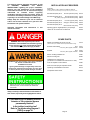
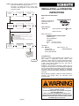
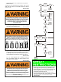
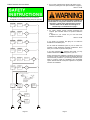
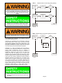
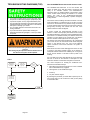
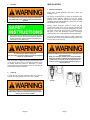
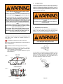
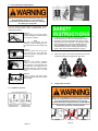
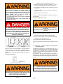
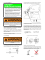
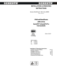
INSTALLATION- and OPERATING
INSTRUCTIONS
Safety
through
Technology
Edition 04/2002
Order No.: EA 4.3
INT / USA / 5 / R
Patents granted in
Patente wurden erteilt in
DE
GB
I
USA
3 735 077
2 211 070
1 207 344
4 854 608
Installation and Operating Instructions
01 - 29
Questions about Installation
01 - 04
How the Schroth asm-autocontrol works
05
Package Contents
06
Installation
07 - 22
Operating
22 - 28
Care and Maintenance
28 - 31
Troubleshooting Diagrams (TSD)
32 - 36
Accessories and Spare Parts
37
Certified Vehicle List (Vehicle Reference List)
yellow page
GEPRÜFT
UND
ÜBERWACHT
TESTED
AND
INSPECTED
asm-autocontrol
This manual contains important information as well
as
DANGERs,
WARNINGs
and
SAFETY
INSTRUCTIONs regarding the proper installation,
effective use and maintenance of the SCHROTH
harnessbelt. Please be sure to read and thoroughly
understand
its
contents
before
beginning
installation and before using the system. Follow all
instructions and Safety Instructions carefully and be
especially sure to heed all Dangers and Warnings.
Always keep this manual in your car for reference
and be sure to leave it with the car if you sell it with
the harness belt system installed.
Important information and instructions in this
manual are shown:
INSTALLATION ACCESSORIES
Color key:
black=0, blue=1, red=2, yellow=3, purple=5, green=8
The X in PINs must be substituted by the color key of the color you want to order!
Shoulder belt pads, pair of
black with yellow flock printing
00109
Shoulder belt pads, pair of
blue with black flock printing 01109
red, yellow, purple, green with black flock printing 0X109
Shoulder belt pads, pair of
black with grey flock printing
09109
Shoulder belt pads, pair of
silvergrey w. black flock printing
09209
Shoulder belt pads, pair of
black with black flock printing
09309
Adjusting grips for length adjuster, 4 pcs./package
00092
"Switch off" for manual lock of inertia reel
00096
SPARE PARTS
DANGER deals with important points about
installation of the SCHROTH harnessbelt. Ignoring
these warnings will create serious danger which
can lead to serious personal injury or death.
WARNINGS deal with important issues about installation,
use, misuse or modification of the
SCHROTH harnessbelt.
Ignoring these Warnings will significantly reduce the
performance of the harness belt system. This can result
in serious personal injury or death during an accident.
•
Adapter for installation at anchor point "D"
01103
(refers to index Y) of Certified Vehicle List (Vehicle Reference List))
Retractor with webbing
black
blue, red, yellow, purple, multicolor
01170
0117X
Side belt
black
blue, red, yellow, purple, multicolor
01120
0112X
Sensor including installation kit
01090
Wire kit including fuse
00098
Installation kit for harness belt
(w/o Sensor incl. installation kit and wire kit incl. fuse)
01097
Cover for adjuster inclusive retainer
01084
Slide cover and spring for separation buckle
00087
Operating- and Installation Instructions
EA 4.3
Transparent interior sticker
W26ST
Safety Instructions contain important hints to help you
effectively install, use and maintain the SCHROTH
harnessbelt.
Always carefully read and follow the information in
this manual, especially those highlighted as above.
If you cannot pull out webbing from the
retractor or if the retractor appears
permanently blocked –
Is the ignition is switched on?
Refer to Troubleshooting Diagram 5
[TSD 5] on page 36.
Page 37
TSD 5 (Only use this instruction if all sources of malfunction
have been eliminated according to TSD 4.)
The latch is touching the cover of the recoil
mechanism. With the ignition on, the rear tail strap
cannot be uncoiled.
Ignition is
turned on?
no
Turn ignition
on.
Belt can be
uncoiled?
INSTALLATION- and OPERATING
INSTRUCTIONS
yes
Approvals asm-autocontrol
yes
no
USA:
Tested in accordance with
applicable provisions of
FMVSS 209
Vehicle is on
level ground?
no
Move vehicle
to level ground.
Belt can be
uncoiled?
i
yes
Other Countries:
Rallye 3 A
yes
®
Approval-Number: Ser 4m E13 040396
no
Made in Germany
Made in Germany by:
With the ignition on, vigorously pull the tail strap 1"-1½" out
of the recoil mechanism.
If necessary put a srewdriver through the hole in the latch in
order to have a better grip.
Now slowly recoil the pulled out belt.
The locking mechanism should release with this manoeuvre.
SCHROTH Safety Products GmbH
Postfach 24 40
59714 ARNSBERG
GERMANY
Phone
Fax
Recoil
mechanism
moving freely?
no
Repeat above
instructions.
Belt can be
uncoiled?
yes
+ 49 - 29 32 - 97 42-0
+ 49 - 29 32 - 97 42-42
Imported by:
USA: MDI Inc.
Other Countries: see
3 First Avenue
www.schroth.com
Peabody, MA 01960
Phone (888) 536-8550
no
Send retractor
to importer for
inspection.
Congratulations!
END
With the purchase of this SCHROTH asm harnessbelt, you
have chosen a sophisticated restraint system, which
represents a further advance in harness restraint technology.
Extensive research, testing and field experience has shown it
to offer, when properly installed and worn, high levels of
protection in head-on collisions.
SCHROTH asm-autocontrol harnessbelt systems with the
emergency locking retractor are only intended for installation at
the left and right outboard front seating positions of passenger
cars which have been specifically evaluated by SCHROTH
engineers for anchor point locations and suitability of available
front seats.
Before attempting installation, please first answer the following
questions and carefully follow the instructions which
accompany them.
Restraint systems can only offer protection if they are
properly installed and used.
To assure proper function, your car must meet special
technical requirements.
Before installation of SCHROTH harnessbelt, please
answer a few very important questions to make sure the
SCHROTH harnessbelt system can be properly installed
and effectively used in your car..
Page 36
Page 1
1. Is your vehicle listed in the Certified Vehicle List (Vehicle
Reference List)?
Power at
testing point
4?
Compare your car’s specifications to the Make, Type No. and
Model Year of vehicle in the Certified Vehicle List (Vehicle
Reference List).
YES
no
a) Make sure plugs
are well connected to the sensor.
b) Install the sensor
in a permanent
vertical position.
Function
O.K.?
yes
yes
no
Send retractor
to importer
for inspection.
NO
Power at
testing point
5?
no
Replace defective
control wire
(red/black). Use
only SCHROTH
Spare Parts.
yes
1. Remove rubber
cover (see page 26).
2. Check the wire connection and holder.
3. Power at testing
points 7 and 8?
(Positive and
negative terminals.)
Check testing
points 7 and 8.
Proper harness belt geometry requires that seat belt
anchor points be located within narrowly defined areas.
Therefore SCHROTH harnessbelts may only be installed
in SCHROTH approved vehicles for which proper
anchorage location and belt geometry has been
determined to exist.
Power at
testing point
7?
no
Replace defective
control wire
(red/black). Use
only SCHROTH
Spare Parts.
no
Send retractor
to importer
for inspection.
yes
Power at
testing point
8?
2. Are there openings between the backrest and the headrest
of the seat? (See illustration below.)
YES
NO
yes
Replace defective
ground wire. Use
only SCHROTH
Spare Parts.
Function
O.K.?
yes
no
Harness belt system will not function properly and must
not be installed in vehicles equipped with seats having no
headrest or backrests with integrated headrest. (No
openings exist between the backrest and the headrest.)
Never create a new opening in the seats installed in your car.
Eye of ground
wire correctly
installed? See
pages 12 and
15.)
no
Eye properly
located?
Function
O.K.?
yes
no
yes
Test power between testing point 6 and bolt head.
With a proper connection, the test lamp (voltmeter) will not show voltage.
Ground
connection OK
between bolt
and chassis?
yes
right
right
right
wrong
3. If you intend to install the tail straps of the SCHROTH
harnessbelt system at the rear seat lap belt anchor point
a. have you made sure that the Certified Vehicle List
(Vehicle Reference List) allows or requires you to do so?
Function
O.K.?
no
Power
measureable?
yes
Ground
connection is
not OK. Please
go back to I and
start again.
no
NO
b. is your vehicle equipped with a SCHROTH approved
seat? (see Certified Vehicle List (Vehicle Reference List)
and Legend on yellow pages)
YES
NO
Installation to anchor points located lower than the front
seat backrest with an unapproved seat can result in
serious personal injury or death. Never install the
SCHROTH harnessbelt at these lower anchor points
unless this installation is allowed for your vehicle’s make,
model and model year and it is used with an approved
seat. [See Certified Vehicle List (Vehicle Reference List)
and heed all indexes.]
END
Send retractor
to importer
for inspection.
•
Page 2
Change position
of eye in the
assembly and
remove paint from
the thread.
Test again the
current between
testing point 6
and bolt head.
wrong
YES
no
•
The recoil mechanism could remain permanently locked, if
the tail strap is disconnected from the separation buckle
while the ignition is off! The tail strap will be reeled in by
the recoil mechanism. If the latch of the belt hits the cover
without being slowed down, it might cause the recoil
mechanism to permanently lock up.
If you disconnect the belt from the separation buckle,
make sure that the tail strap is slowly reeled in by manually
slowing the retraction. This will prevent the abovedescribed effect.
Page 35
4. Do you have a left belt for the driver’s side and/or a right
belt for the passenger’s side? (See illustrations on page 5.)
TSD 4 Retractor does not release.
YES
•
The retractor will not release if your car is more than
20 degrees out of horizontal position (steep hill, high curb).
Ignition turned
on?
no
yes
Voltage of vehicle
OK (min. 9 Volt)?
no
Provide for
correct proper
voltage.
no
no
Connect fuse wire
to another power
supply wire (see
pages 19 to 22).
yes
Function
O.K.?
If you answer any question with [NO], do not install the
SCHROTH harnessbelt system.
no
Do not install the SCHROTH system in your car unless it is
possible to make SCHROTH approved modifications, which
allow you to answer all questions with [YES].
Repair the
vehicles wiring
and insert a
new fuse.
yes
Function
O.K.?
If you have answered ALL questions with [YES], you may
install the SCHROTH harnessbelt system in your car.
no
no
Check wiring of
harness belt for
short circuit
and repair it.
Insert new 5
Ampère fuse.
Function
O.K.?
yes
All plugs are
connected as
required?
5. For certain vehicles special mounting accessories are
required. [See Certified Vehicle List (Vehicle Reference
List).]
If required for your vehicle: do you now have them
available for installation?
YES
NO
no
yes
In-line fuse
OK?
yes
Function
O.K.?
yes
Fuse in fuse
box OK?
Left and right belts are not interchangeable! Installation of
harness belts on wrong side of vehicle can cause severe
head injury or death during rebound phase of frontal
collision! Make sure the black asm-cartridge is on
inboard strap - see illustrations on page 7.
no
yes
Supply wire always
powered if ignition
is turned on?
yes
Function
O.K.?
Turn on ignition.
yes
no
no
Check all
electrical
connections as
instructed on
pages 18 to 22.
Please remember that installation procedures will require you
to perform a variety of operations requiring familiarity with tools
and mechanical procedures. If you have any doubt about your
ability to properly install the SCHROTH asm harnessbelt
system, take this manual and all parts supplied to a competent
mechanic for installation.
yes
Function
O.K.?
yes
no
Use test lamp (voltmeter with probe) and always test between wire and vehicle body. Follow
step by step the numbers of testing point indication.
8
7
6
1
5
br
4
fuse wire
connector
to current
supply wire
r/bl
r/blue
3
2
1 = exit of fuse wire, close to connector
2 = exit of main wire, close to fuse holder
3 = close to plug of sensor
4 = close to exit-plug of sensor
5 = close to inertia reel
6 = eye of ground wire
7 = plug+ of magnet
8 = plug- of magnet
Test point 6 for
power.
yes
no
Remove ground
wire from anchor
bolt and test for
voltage between
eye and chassis.
no
yes
Power at
testing point
2?
Power at
testing point
1?
no
a) Correct power
supply lead?
b) Reconnect the
fuse wire to the
power supply
lead.
yes
no
Make sure the
connection to
the main wire is
OK.
no
Replace main
wire (red/blue).
Use only
SCHROTH Spare
yes
Power at
testing point
3?
yes
next page
NO
next page
next page
Page 34
Page 3
TSD 2
Retractor does not lock during heavy braking.
Is the sensor
mounted in
vertical
position?
Please follow these instructions carefully while installing
and before using the belt! Failure to follow instructions
can not only damage and reduce the performance of the
system, but may also result in the denial of warranty
claims.
no
Install as
instructed on
pages 15 to 16.
yes
Wiring OK, (see
page 17 to 22)?
No short circuit
in the wiring to
sensor?
SCHROTH asm harnessbelts are designed to be installed
in addition to the stock restraint systems. Always heed
Country/State laws governing the wearing of seat belts.
yes
no
no
Rewire in
accordance
with
instructions.
yes
•
Function
O.K.?
Function
O.K.?
yes
no
END
Send retractor
to importer
for inspection.
TSD 3 Retractor does not lock when ignition is turned off.
Be sure that the tail strap of the harness belt is not interfered with or misdirected by cargo or by folding rear seat.
This SCHROTH asm harnessbelt is only suitable for adults on
front outboard seating positions.
Supply lead is
without power
if ignition is
turned off?
no
Choose
another power
supply lead
yes
SCHROTH asm harnessbelts are not intended or suited for
use by children under 12 years of age, or persons who weigh
less than 88 lbs (40 kg) or those who are less than 4'11" tall
(1,50 meters), regardless of age. Such persons will not be
adequately protected by the harness system and may receive
more severe injury than would otherwise be expected.
SCHROTH U.S. model harnessbelts have been tested in
accordance with performance parameters of Federal Motor
Vehicle Safety Standard 209 with the exception of
Paragraph S 4.6 (full scale impact testing as described in
FMVSS 208). FMVSS 209 deals with lap and three point
restraints and does not expressly refer to harness belts.
SCHROTH has nevertheless applied the performance criteria
specified in FMVSS 209 to the system to the extent applicable.
Always keep this manual in the vehicle so that others can
thoroughly familiarize themselves with the proper use of
the system.
Page 4
yes
no
Check the
wiring diagram
of your vehicle
for assistence.
END
Send retractor
to importer
for inspection.
These belts, when properly installed and used according to
applicable instructions can mitigate injury. The ability of any
restraint system to mitigate or prevent injury is directly related
to the type and severity of the accident. SCHROTH asm
harnessbelts have been tested in dynamic sled tests utilizing a
75 kg (165 lbs) Hybrid II anthropometric dummy to simulate
head-on collisions at 50 km/h (31 mph). They also have been
dynamically tested utilizing a 75 kg mass dummy in
accordance with European Safety Standard ECE-R 16.04.
•
Function
O.K.?
(see pages 19/20)
Page 33
TROUBLESHOOTING DIAGRAMS (TSD)
How the SCHROTH asm-autocontrol retractor works
•
The SCHROTH asm-autocontrol is the first harness belt
system for street use to offer the comfort, convenience and
safety of an automatic retractor. The SCHROTH asmautocontrol gives you greater freedom of movement to reach
vehicle controls while providing the benefits of a harness
system. The heart of the SCHROTH asm-autocontrol
harnessbelt is an electro-magnetically operated emergency
locking retractor.
•
•
•
If you have a problem and do not know the cause, follow
the specific Troubleshooting Diagram (TSD) step by step.
If parts are required, use only original SCHROTH parts.
They are designed especially for the harness belt system.
Unauthorized parts can cause malfunction of the harness
belt system or damage your vehicle.
For your safety: Repairs to the retractor and sensor are
strictly prohibited!
If you cannot solve the problem after following the
applicable Troubleshooting Diagram, contact your dealer
or importer.
Never use the harness belt system if it does not function
properly.
Safe driving may be impossible and the effectiveness of
the harness belt system will be impaired.
A sensor controls the electro-magnetic operation of the
retractor. In order to work properly and react to forces coming
from different directions, the sensor must be installed vertically.
If the sensor is not installed vertically, the retractor will be more
sensitive to forces applied to the vehicle from one direction
than from another and the system will not work properly.
The retractor will unlock allowing webbing to be unreeled and
you to move as soon as current flows to the electric-magnetic
system in the retractor from your car’s 12-volt electrical
system. Electrical current flows whenever the ignition is
switched on.
When forces act on the vehicle that trigger the sensor, the flow
of current to the electro-magnetic system of the retractor is
interrupted and the retractor locks. Webbing can no longer be
let out, but the retractor is still able to take up slack in the
webbing.
For your safety, the system was designed to lock up whenever
the flow of current to the retractor is interrupted. For that
reason the retractor is locked when the ignition is turned off.
TSD 1
Is the retractor
aligned with
the direction of
tail strap?
The retractor is both, webbing and vehicle sensitive. It will lock
when belt webbing is unreeled too fast. It will also lock when
forces act on the vehicle from any direction during an accident
or during extreme driving maneuvers such as heavy braking or
during sharp cornering. The retractor will also lock if the
vehicle is tilted more than 25 degrees.
no
Align the
retractor (see
page 14)
yes
Function
O.K.?
yes
The correct sequence for buckling the SCHROTH asmautocontrol harnessbelt is always:
1. after making sure that the transmission is in Park or Neutral
with the hand brake firmly engaged,
no
2. switch ignition on, but do not start engine,
3. buckle up,
4. only then, start the engine.
By following this procedure you will be able to prevent your car
from moving when you do not want it to while you are putting
on the harness belt.
Lubricate with
resin free oil
(see page 29)
Function
O.K.?
END
yes
no
Send retractor
to importer
for inspection.
Page 32
Page 5
Schroth reserves the right to incorporate any technical
changes or further development in this product without
notice.
PACKAGE CONTENTS
US version
international version
Ser 4m
E13
If you need additional information or have any comments
or questions about the SCHROTH asm harnessbelts,
please contact your dealer or the importer.
[see www.schroth.com]
Model: Rallye 3A
Tested FMVSS 209
Imported by:
MDI Inc. Peabody, MA
Typ: Rallye 3A
week
040396
year
no. of manufacture
Prod.-Number
Prod.-Number
In North America please contact:
Date of manufacture
(week/year)
Date of manufacture
(week / year)
MDI Inc.
certification number
(ECE -R 16)
3 First Avenue
Peabody, MA 01960
Toll Free (888) 536-8550
Phone (978) 532-1145
Fax (978) 532-2016
Importer
Type of belt
Installation hardware
for harness belt
Bracket for C-pillar mounting
Bolt 7/16", length 1½"
Bolt 7/16", length 1"
Bolt 7/16", length ¾"
Washer
Spacer sleeve
Spring washer
Hexagon nut 7/16"
Cover for bolt head
Cover for hex nut
Transparent Sticker (indoor)
SCHROTH asm sticker
for sensor
1x
1x
2x
1x
1x
1x
4x
1x
2x
1x
1x
1x
Perforated metal strip
Sheet metal screw
Hex bolt 4 mm
Spring washer 4 mm
Hexagon nut 4 mm
Fuse 5 Ampere (blade type)
Fuse wire (red/blue, with
2 connectors)
Main wire (red/blue)
Cable grommet
Bubble level [only USA]
1x
2x
2x
2x
2x
1x
1x
1x
1x
1x
Our Service Number
(800) 884-BELT
guides you to your nearest dealer.
REMEMBER:
For safety’s sake, always buckle up.
®
SCHROTH and SCHROTH-asm are registered trademarks of
SCHROTH Safety Products GmbH, Germany.
®
The SCHROTH-asm safety system is patented in several European
countries, the United States and Japan.
The copyrights of this Installation and Operating manual are
property of SCHROTH Safety Products GmbH, Germany.
Copyright of this part or in hole, on paper, on film or
electronically is allowed only after written permission by
SCHROTH Safety Products GmbH, Germany.
© 2002, SCHROTH Safety Products GmbH, Arnsberg, Germany.
Page 6
Printed in Germany
Page 31
4
Accident
INSTALLATION
1 General Instructions
Always leave original equipment seat belts in place and
available for use.
A safety belt which was in use during an accident has
been weakened and is unfit for further use and must be
replaced!
We strongly recommend that you leave the standard 3-point
restraint system originally supplied for the front seating
positions of your vehicle as well as those systems originally
installed for the rear seating positions in place when you install
the SCHROTH asm harnessbelt.
Leaving original equipment systems in place and fully
functional will enable you to use the vehicle’s standard seat
belts when it is necessary to transport passengers in any of the
rear seats or when either harness belt is not suited for use by
the driver or front seat passenger. Removal of equipment
restraint systems may violate applicable State or Federal law.
•
One indication that the belt was exposed to excess strain
and therefore requires replacement is when the stitches of
the asm-system are ripped open and are protruding from
underneath the asm-plastic cover.
A restitched asm seam is dangerous.
The asm energy conversion device may not be restitched
under any circumstances.
After an accident, in addition to replacing seat belt which were
in use, also be sure to ask your car dealer for carefully check
all seatbelt attachment points for deformation or cracks.
Always make sure that the guidelines of the car manufacturer
are followed if a repair is necessary.
5
To use the standard 3-point restraint system, release the
SCHROTH asm-autocontrol tail straps and store both the front
and rear sections out of the way
Separate SCHROTH asm harnessbelts are supplied for the
left and right sides.
Black asm cartridge must be on the inboard shoulder
strap when system is installed (see illustration). Never
install belt on wrong side of vehicle. System will not
function properly in an accident and serious injury or
death may occur.
Cleaning
To clean the belt, use soap and warm water. Do not use any
solvents! Do not dry the belt in the sun or near a radiator.
Improper cleaning or drying of the harness belts can
weaken them, reduce their effectiveness and can result in
serious personal injury or death.
Page 30
Page 7
2
Troubleshooting
In the event problems arise which have been caused by
incorrect installation or the vehicle’s electrical system, we have
prepared a Troubleshooting Diagram (see page 32), which will
assist you in finding and eliminating the cause. Be sure to
choose the specific diagram that describes your problem and
carefully follow the instructions.
Use of improper attachment points will impair system
performance.
Weak tail strap anchor points will not withstand the forces
in an accident and increase the risk of personal injury in an
accident.
Never attach the tail strap to anchorages intended for the
tether straps of child seats that are found on the filler
panels behind the rear seats of some passenger cars or the
luggage area of some hatchbacks or station wagons. These
anchor points are not strong enough to withstand the
forces of an accident and are not intended for adult safety
belts.
Harness belt systems may only be installed at suitable
anchor points for seat belt systems as originally installed
by the vehicle manufacturer.
For suitable anchor points for make, model and model
year of your vehicle, see Certified Vehicle List (Vehicle
Reference List). If in doubt, ask your dealer to show you
where these anchor points are located.
Never use any restraint system that does not function
properly.
If questions arise, immediately contact your importer or
the manufacturer!
3
Maintenance of the retractor
If the retractor is very noisy when unreeling or retracting the tail
strap or you note reduced tension at the tail strap, follow
Program 1 in the Troubleshooting Diagram (see page 32).
These figures show the general location and suitability of seat
belt anchor points installed as standard equipment in
passenger cars.
Not suitable for attachment of an asm-autocontrol.
Must be used for the attachment of the lap belt portion of
the harness belt.
When removing and replacing the rubber cover be careful
not to damage the wiring of the retractor.
Suitable for retractor anchorage of asm-autocontrol.
Retractor anchorage to anchor points “D” or “E” only if
allowed for your vehicle’s make, model and model year
and it is used with an approved seat.
[See Certified Vehicle List (Vehicle Reference List) and
heed all indexes.]
SIDE VIEW
Figure 1
B-pillar
Turn the ignition on and pull the strap out completely. Turn the
ignition off to lock the belt at full extension. Put one drop of a
resin free oil (sewing machine oil) onto the bearing of the axle.
Also put 2 or 3 drops through the hole of the plastic cover to
the spring. Replace the rubber cover carefully.
C-pillar
A-pillar
C
D+E
OVERHEAD VIEW
Figure 2
D
C
A-pillar
B-pillar
Page 8
E
C-pillar
Page 29
•
9
As a constant reminder, the enclosed transparent sticker
must be attached to the rear side window in a prominent
place. The sticker cannot be removed without damage to
chromate tinted glass. On such vehicles, you may affix the
transparent sticker at a different, prominent location so that
it will serve as a constant reminder.
Stowing the belts when not in use
If you use the stock 3-point belt instead of the SCHROTH
harnessbelt, be sure to properly stow the harness belt.
Buckle the lap belt in the space between the backrest and the
seat. This prevents the belt from being pinched by the door,
the seat tracks or backrest adjustment mechanism and also
helps prevent the belt from being soiled. Open the separation
buckle on the tail strap at harness belt system and stow the
shoulder straps as well in the space between the backrest and
the seat.
CARE and MAINTENANCE
1
Never drill or tap or make a new attachment point in
the body or chassis in order to mount a SCHROTH
harness at that location. Such attachment points are
inadequate, may be improperly located and can
seriously impair the function and effectiveness of
the system.
Please compare the possible mounting locations on your car
with the illustrations on pages 9/11 and pick the one that you
find most suitable.
Original equipment belts with swivel attachments must never
be bent, modified, impeded or restricted in their range of
motion.
2 Anchorage bolts
Bolts used to attach original equipment seatbelts may be used
to attach the SCHROTH asm harnessbelt if they are long
enough. You must be able to tighten each bolt a minimum of
nine (9) full 360 degree turns. If the bolt is too short, choose
one of the SCHROTH supplied bolts. (Read and observe the
following Warning!)
Inspection
Check the safety belt once a month for any damage. Cuts,
tears and other damage to the belt will greatly reduce its
effectiveness. Replace the belt or damaged parts immediately
with original Spare Parts (see page 37, Spare Parts). Never
use a damaged harness belt, use the standard 3-point belts
which remain available for use.
Make sure the buckles are free of any obstruction and lock
securely.
A bolt which sticks out too far might damage the chassis,
the fuel tank, fuel lines, brake lines or other important
vehicle components.
Make sure enough space is available behind the thread
before screwing in the 1½ inch (38 mm) long bolt.
Tightening torque for all bolts: 30 ft.lbs. (40 Nm)
3 Installation of the lap belt
Modified belts or such belts that have been resewn are not
strong enough and are dangerous in an accident.
Never modify, disassemble or repair the belts yourself.
For parts that can be replaced, use only original SCHROTH
Spare Parts.
Only original SCHROTH Accessories may be used with the
harness belt system.
Use of non-authorized parts and Accessories can reduce
the effectiveness of the harness belt system.
•
When mounting the lap belt in a car
equipped with a racing seat and integrated
(non adjustable) headrests thread the belt
through the openings as illustrated.
Any changes made to the belt will automatically void the
warranty.
Page 28
Page 9
3.1 Re-assembling the length adjuster
We do not recommend disassembling the length adjuster
during installation process. It is not necessary to
disassemble the harness belt in order to run it through
the openings of racing seats.
If for any reason the length adjuster is disassembled, strictly
follow the procedure step by step as described below to reassemble the adjuster.
Figure A:
Fold the strap to a loop and insert it
upwards throughout the metal frame and
turn the loop as indicated.
•
In order to get an even tighter fit of the lap belt, we
recommend that you move your seat back a little, adjust
the length of your belt as described above and move the
seat forward to its normal position. This will help to tighten
the lap belt even more. This recommendation does not
apply when both attachment points of the lap belt are
mounted directly to a seat on a sliding track and runner
system, rather than one attached directly to the floor.
b)
Adjust the length of the inboard shoulder belt until both
belts exert equal pressure against the upper torso.
Note:
The strap part protruding from the
adjuster for further adjustment [1] must
be located above the stress taking strap
[2].
Figure B:
Position the plastic cover on top of the
loop and insert the metal retainer [3]
through the guides of the plastic cover
and the strap loop.
Figure C:
Keep the metal retainer positioned
between your thumb and forefinger.
Slide the plastic cover backwards onto
the metal frame as indicated until both
ratchets [4] locks with a distinct clicking
sound into the detentions in the metal
frame.
Figure D:
Check by pulling both stress taking
straps [2] and [2`] the adjustment device
will lock safely.
equal pressure
RIGHT
8
WRONG
Using of the rear seats
3.2 Installation locations
at or on the center tunnel
Never wear the SCHROTH harnessbelt if any rear seating
position is occupied. Both front seat occupants must then
use original equipment 3-point belts. The rear seat
occupant could interact with the tail strap of the SCHROTH
harnessbelt during an accident and cause serious injury to
himself or to the wearer of the harness belt.
right way
Page 10
wrong way
Page 27
right way
have the same pressure over the shoulders and in the
chest area.
Make sure the shoulder straps are properly adjusted whenever
the SCHROTH harnessbelt is worn. For lap belt adjustment
see following paragraph.
7
Putting on the belt
a)
First turn on the ignition to activate and release the
retractor mechanism. There is no need to start the
engine!
Damage will impair the effectiveness of the harness belt
system!
Make sure that the seat and bracket are positioned so that
moving parts of the seat or adjustment mechanisms cannot
contact or damage the webbing of lap belt.
(See paragraph 4, Flexible range of the seat belt mounting
brackets.)
at the seat
on the seat sliding bracket
•
b)
For your safety the retractor will lock at any time the
ignition is turned off or whenever power to the retractor is
interrupted.
After choosing the correct seating position, put on the belt
and adjust the lap belt so it fits tightly in the bend
between the pelvic crest and the upper thigh. The release
buckle should be located in the center in front of your
body.
Mounting point on
sliding anchor point
on the seat bracket
of seat with height
adjustment.
Illustration shows
AUDI/VW installation.
3.3 at the door sill
Use the foremost anchor point of the
sliding bar of the stock 3-point belt.
close buckle
tighten lap belt
WRONG
Improper fit of any lap belt can cause serious personal
injury or death.
• ALWAYS make sure that the lap belt is tightly adjusted.
A lap belt in a harness or 3-point system that is too
loose will impair the performance of the system.
• The lap belt must fit tightly in the bend between the
pelvic crest and the upper thigh!
• Make sure belt is properly adjusted when a different
person uses the belt or each time the seat is readjusted.
(Heed WARNING on adjuster.)
Page 26
Page 11
4
Flexible range of the seat belt mounting brackets
5
How to adjust the belt
5.1 to lengthen the belt
Hold the adjuster at right angles
- 90° - to the belt and pull in
direction of the arrow (see
illustration beside).
Repeated bending could weaken the bracket and cause it
to fail when loaded in an accident.
Never bend the bracket back and forth several times.
Any pivoting brackets of the stock 3-point belts must not
be limited in their range of motion.
5.2 to shorten the belt
Pull the end of the strap in
direction of the arrow (see
illustration beside).
SCHROTH offers accessory adjusting grips which can make
the adjustment even more convenient (see page 37,
Accessories).
6
5
Installation of retractor and ground wire
Adjustment of the headrest and initial adjustment
of the tail strap
6.1 Retractor installed at anchor point "C"
anchor points are not suitable
attachment of the lap belt portion of the harness belt
anchor points “C” are suitable
anchor points “D” and/or “E” are suitable only if allowed
for your vehicle’s make, model and model year and it is
used with an approved seat
[See Certified Vehicle List (Vehicle Reference List) and
heed all indexes.]
B-pillar
C-pillar
A-pillar
C
wrong way
right way
The shoulder belts must not
sag or be pulled downwards.
Headrests must not restrict
movement of the shoulder
belts.
The headrest is properly
adjusted and the shoulder
belts can move freely
without slack.
6.2 Retractor installed at anchor point "D" or “E”
D+E
WRONG
D
C
A-pillar
B-pillar
E
C-pillar
If retractor is installed at anchor point "C"
(without stock 3-point belts for outboard rear seats)
If necessary open panel covering at anchor point "C"
use spacer sleeve [1].
wrong way
wrong way
right way
Belts must not have
any sag.
The tail strap must
not be misdirected
by upholsteries or
the rear seat
cushions.
The headrest is
properly adjusted
and the shoulder
belts can move
freely without
slack.
Bolt retractor directly to the anchor point
1 = bolt
2 = spring washer
3 = eye of ground wire
4 = retractor
To assure a proper ground, make sure
that the eye of the ground wire is located
between the spring washer and retractor
body (or the C-pillar mounting bracket, if
used). Take care not to crack the wire
when tightening.
Page 12
a) After choosing the correct seating position, put the belt on
and adjust the lap belt so it fits tightly in the bend between
the pelvic crest and the upper thigh. The release buckle
should be located in the center in front of your body. If
necessary, lengthen the tail strap first.
b) Next adjust the shoulder belts: Make sure there is approx.
4 inches (10 cm) of loose belt protruding from each
shoulder belt adjuster.
c) One of the two shoulder belts should now be tight against
the shoulder, the other shoulder belt should be looser.
d) Tighten the looser shoulder belt until both shoulder belts
Page 25
3
Installation with bracket for C-pillar mounting
Routing of the shoulder belts
Choose the positioning of the bracket depending on the
installation situation as shown below.
Also select the position at the bracket for the installation of the
retractor.
Heed following WARNINGs!
Distance between headrest
guides min. 4¾" (120 mm).
•
4
If there is only one headrest post or
if the distance between 2 posts is
less than 4¾" (120 mm).
For vehicles equipped with stock seats not suitable for use
with harness belt systems, special seats are required. See
Certified Vehicle List (Vehicle Reference List).
How to close and release the buckles
4.1 Lap belt buckle
To close:
Insert the latch into the buckle until you can hear a
distinct clicking sound.
To open:
Depressing the red button marked "PRESS" will
open the buckle.
4.2 Buckle between tail
(separation buckle).
To close:
strap
and
shoulder
The retractor
1. must be installed at a sufficient distance from the stock
3-point belt swivel attachment so the range of motion of
the stock belt is not restricted,
2. must be located as far as possible to the rear of the car.
The retractor must be well away from the head of the
rear seat passenger and the rear door,
3. must be positioned in direction of the pull of tail strap
when the belt is worn (see illustration).
4. must not lay on the backrest of the rear seat, so that it
cannot be positioned in direction of the tail strap
webbing.
Assembly for installation of the retractor to the bracket.
belts
Insert the latch underneath the plastic cover until it
locks in (1) and the plastic cover slides back into
its normal position (2).
Bolt length: ¾"
•
To open:
Slide the plastic cover in the direction of the arrow
to the stop (1). Tilt the latch downwards and
remove it from the buckle (2).
Depending on the design of the anchorage of the stock 3point belt, the C-pillar mounting bracket [1] must be
attached to the original assembly so that swivel
attachments will not be impeded or restricted in their range
of motion.
The SCHROTH bracket [1] can be carefully bend up to an
angle of 45 degrees and be twisted up to 90 degrees.
Page 24
Page 13
Never bend the bracket back and forth several times.
Repeated bending could weaken the bracket and cause it
to fail when loaded in an accident.
The arrows indicate the direction of the tail strap webbing.
right way
right way
right way
right way
wrong way
wrong way
wrong way
wrong way
If retractor is installed at anchor point "D" or “E”
Installation to anchor points located lower than the front
seat backrest with an unapproved seat can result in
serious personal injury or death. Never install the
SCHROTH harnessbelt at these lower anchor points
unless this installation is allowed for your vehicle’s make,
model and model year and it is used with an approved
seat. [See Certified Vehicle List (Vehicle Reference List)
and heed all indexes.]
Page 14
Improper use of any seatbelt can cause serious personal
injury or death.
To help reduce the risk of serious injury in an accident:
• Never strap more than one person in place, with each
harness system.
• Never wear the harness system at the same time as the
original equipment seat belts.
• Never use the lap belt portion of the harness system
without the shoulder belts.
• Always make sure that lap belt and shoulder belts are
not twisted when worn.
• Never use the harness belt system for children under
the age of 12 years or to install an infant seat or child
seat.
• Never use the harness belt system for persons who
weigh less than 88 lbs or those who are less than 4`11"
tall, regardless of age.
• Always wear the lap belt portion of the harness system
low and tight across the pelvis. This is also
recommended for the stock 3-point belt whenever it is worn.
• Never wear the belts over heavy clothing as it can
interfere with proper positioning and adjustment of the
belts, reducing the overall effectiveness of the system.
• Never wear the belts over rigid or breakable objects in
or on your clothing, such as cell phones, eye glasses,
pens, jewelry keys etc. as these may cause injury.
• Never allow lap or shoulder belts to rub against sharp
objects.
• Never allow the belts to be damaged by becoming
caught in door or seat hardware.
2
Adjustment of the seating position
Choose your most comfortable seating position for safe
driving.
Driving and safety instructors recommend:
"Select your seating position in the vehicle so that you can fully
grip the upper edge of the steering wheel with your elbow still
slightly bent and without moving your upper body from the
seatback. With the clutch (automatic transmission-brake) fully
depressed your knee should still be slightly bent."
Remember: A "laid back" seating position might look 'cool', but
does not contribute in any way to better or safer handling of
your vehicle! No racing or rallye driver is "laid back" in his
vehicle!
Page 23
Vehicles fully equipped with rear seats and rear lap and
shoulder seat belts.
For installation adapter part no. 01003 [USA: 01103] is necessary.
Wiring diagram:
The eye of the ground wire must be fixed
with the bolt at the anchor point, because
the adapter is an insulator.
The fuse holder is equipped with a common blade type 5
Ampere. The fuse protects against discharging of the battery
or fire in case of a short circuit.
Use only 5 Ampere fuses!
If a fuse blows first check the wiring and replace damaged
wires with original spare parts (see page 34) before you
insert a new fuse.
In order to help you quickly locate the cause of possible
problems with the electrical system of the SCHROTH asmautocontrol harnessbelts, we have prepared a Troubleshooting
Diagram (see page 32). Please follow the specific diagram
step by step if the retractor should not unlock when the ignition
is turned on.
Align the adapter and retractor carefully before tightening
the bolts to prevent twisting or kinking of the tail strap
webbing and to make sure that the webbing can freely
move in and out of the retractor without interference when
the harness belt is in use.
Webbing which is twisted or kinked or cannot move freely,
can damage the webbing and will reduce the effectiveness
of the harness belt system.
Vehicles with rear seats removed (competition cars).
OPERATING
1
The retractor must be aligned as
shown
and
described
in
paragraph 5.
General instructions
Most Countries require that seat belts be worn by all
passengers when a car is in motion. Please check with your
local authorities for further information! Regardless of the law
in your State, it only makes sense to buckle up, so before you
start your car, make sure that you and all of your passengers
are properly restrained.
The SCHROTH asm harnessbelt system when properly
installed and used according to applicable instructions can
mitigate injury. Of course, the ability of any restraint system to
mitigate or prevent injury is directly related to the type and
severity of the accident.
The following pictures show the correct installation and use of
SCHROTH asm harnessbelts for the specific vehicle depicted.
This vehicle body is one of our test devices used to simulate
head-on collisions at 31 mph. Doors and other components not
required for the evaluation of harness belt performance have
been removed.
6
Installation of the sensor
Improper sensor installation will reduce sensor
performance and impair effectiveness of harness belt
system in an accident.
Install sensor in a precise vertical position. During
installation make sure that the car is parked on a flat, level
surface.
Parking position of the vehicle for sensor installation. Make
sure the vehicle is level side to side and front to rear.
This product is not designed and tested to be used with
HANS® or other head and neck restraints e.g. Hutchens
device.
®
Shoulder belts may slip off the HANS and crotch straps
e.g. of a Hutchens device cannot be properly attached to
the lap belt. Malfunction can result in serious personal
injuries or death.
right way
Page 22
wrong way
Page 15
Do not remove any insulation from the wire!
1. Position power supply lead (from terminal 15 in cars of
German manufacture) in groove (1) of cable connector.
2. Turn shackle (3) including the wire to position it onto the
contacts (2).
Sensor installation at an improper location can promote
aging, corrosion, movement and thereby impair the
effectiveness of the system in an accident. The sensor
must be installed on a rigid structure which does not move
and is in a protected location where it is not exposed to
extreme humidity, heat or dust and cannot be
unintentionally moved out of alignment.
* Do not install the sensor in the engine compartment
(Dust, Water, Salt).
* Do not install the sensor in the footwell (dust and
moisture from shoes).
To install the sensor, you have to drill holes for the
attachment bolts! Be very careful, make sure that you
do not damage the body, the fuel tank, fuel lines,
brake lines or other important components! Apply
the same care when tightening the attachment bolts.
To prevent injury, bolts must never protrude into
passenger compartment.
3. Press the connector with pliers until the shackle (3) is
engaged securely.
The power supply is now connected.
Now attach the main wire (red/blue) running from the sensor to
the fuse holder.
Excess wire length may be cut off.
Make sure no wire is protruding into the passengers
compartment.
The operational safety of the foot controls must not be
restricted!
Do not remove any insulation from the wire!
1. push the wire into the openings (4) of the fuse holder.
2. turn to close the shackle of the fuse holders and press it
with pliers until it is engaged securely.
3. Plug the 5 Ampere fuse into the fuse holder.
The harness belt system will function after the ignition is turned
on.
right way
wrong way
When the sensor is properly installed in a vertical position, it
will function with the same level of sensitivity locking the
retractor when acted upon by sufficient deceleration from any
direction.
Make sure to have enough space underneath the sensor for
the electrical connections.
7.3.3 Wiring of a second SCHROTH asm-autocontrol
harnessbelt system
As described in paragraph 7.3.1 (Current supply wire), it is not
necessary to connect the fuse wire of the second SCHROTH
asm-autocontrol harnessbelt system to the power supply lead
at socket 15 in a vehicle of German manufacture or a similar
socket in another car.
The connection must be made following the instructions in
paragraph 7.3.2, but directly to the main wire (red/blue) of the
first installed harness belt system between its fuse holder and
sensor.
minimum 1“ !
Never connect the fuse wire of the second harness belt
system to the control wire of the first system!
The interaction of both electromagnetic systems may
severely damage other electronic systems of your vehicle.
Short circuits can cause severe damage to your car and its
electrical system. To avoid short circuits, connect the wires
only after installation of all parts of the belt.
Follow on the instructions of paragraph 7.
Page 16
Page 21
7.3.1 Current supply wire
•
•
This figure indicates the most suitable positions for the sensor.
The figure shows a car body with interior panels removed.
The electrical current supply must be taken from a wire
that does not carry current when the ignition is turned off.
The wire selected must be "live" when the ignition is turned
on, but before the engine starts. The flow of electrical
current must not depend on the operation of any other
electrical system or device.
We recommend use of the wire feeding the rear window
defogger, or any wire downstream from the fuse box
running from any terminal marked no.15 (non German
manufactured cars may use other symbols, numbers
and/or letters). Do not connect to the wire that powers the
computerized control system in the vehicle.
If the wiring for the harness belt system is connected to a
wire which carries current even when the ignition is off, the
electro-magnetic components of the harness belt system
could draw current continuously and discharge your car’s
battery while parked.
Check the wiring diagram of your vehicle for a suitable lead,
that can be easily used for proper installation as explained
above. If in doubt, please see your car dealer.
If you install two SCHROTH asm-autocontrol harnessbelt
systems in your car, you only have to connect the electrical
system of the left (driver side) retractor directly to a current
supply of the vehicle.
Be sure to follow the wiring instructions for the right (passenger
side) retractor in paragraph 7.3.3 below.
Only install the sensor directly to a rigid vertical structure of the
car body that does not move.
The mounting holes must be in a straight vertical line and 25/32"
(20 mm) apart. Drill the upper hole first to locate the sensor in
the desired position. Place the bubble level supplied on the top
surface of the sensor to check the front/rear and side-to-side
position. Mark the position for the second hole, drill and
remount the sensor. Recheck the position to make sure the
sensor is leveled.
for self tapping sheet
metal screws, drill holes
5/64" (2 mm).
for 4 mm bolts, drill
holes 13/64" (5 mm)
You can use sensor housing as a stencil.
7.3.2 Connecting
To prevent damage to your car’s electrical system, only
make the following connections when the ignition
is turned off.
The fuse wire can be connected at any suitable position to the
current supply wire (from terminal 15 at fuse box in cars of
German manufacture) by the cable connector included.
Installation with the perforated metal strip
The perforated metal strip can be carefully bent and formed as
necessary for vertical installation of the sensor. Make sure that
both ends of the strap are fixed by screws for permanent and
rigid installation of the sensor on a non-moving structure.
right way
Page 20
wrong way
Page 17
Attach the sensor to the perforated metal strip.
Attachment of the sensor to the strip
quantity
Hex bolt, 4 mm
Spring washer, 4 mm
Hexagon nut, 4 mm
2
2
2
Before drilling make sure no lines, the fuel tank or
the car body will be damaged.
Drill a hole in the structure and secure the upper end of the
strip. Place the supplied level on the top surface of the sensor
to check the front/rear and side to side position of the sensor.
Mark the position of the second hole, drill and secure the lower
end of the strip.
1.
2.
3.
4.
examples for installation
drill 15/32" (12 mm) hole
cut the cable grommet so you can pull it around both wires
run both plugs individually through the hole
push cable grommet into the hole to protect the wires
against or being cut by sharp sheet metal edges
connection with the sensor
Do not bend the strip back and forth more times than
necessary.
Recheck the position to make sure the sensor is leveled.
right
7
right
Wiring
RED/BLUE
RED/BLACK
BROWN
To remove the plug, pull the plastic cover backwards. The
plug will release easily. Never pull on the wire to avoid any
damage and separation from the plug.
7.3
Running the main wire (red/blue) to the current supply wire
wrong
7.1 Wiring diagram
R/Bl
R/S
B
•
Main wire
Control wire
Ground wire
7.2 Connection from the retractor to the sensor
Run the control wire (red/black) from the retractor to the sensor
so that the wire does not protrude into the passenger
compartment and cannot be snagged by the driver or a
passenger and cannot be damaged by cargo, by sharp sheet
metal edges or other objects. If the wire is too long, carefully
stow excess wire close to the sensor.
Be careful when folding rear seats so that their function is not
restricted and the wire cannot be damaged.
If you must drill a hole to lead the wire through an interior panel
be sure to heed the following DANGER and carefully follow the
applicable instructions.
Page 18
Run the main wire (red/blue) to the dashboard or the fuse box
so that it is covered by the floor carpet or the door sill cover.
(See following illustration.)
The wire must not interfere with the foot pedals or with
entry/exit to the vehicle and must not be exposed to damage
by passenger movement. Also make sure that seat adjustment
and movement is not restricted and the wire cannot be
damaged by parts of the seat throughout the seat adjustment
range (back and forth as well as up and down).
Page 19