1
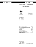
OPERATORS MANUAL
1010
2020
INTELLIGENT FIRE
DETECTION AND
ALARM SYSTEM
SOFTWARE VERSION 3.0
REVISION AUS1
NSW (Head Office)
7 Columbia Court
Norwest Business Park
Baulkham Hills NSW 2153
QLD
16 Lucy St
Moorooka
Qld 4104
VIC
Unit 2 297 Ingles St
Port Melbourne
Vic 3207
Ph:
Fax:
Ph:
Fax:
Ph:
Fax:
(02) 9899-4155
(02) 9899-4156
Notifier Inertia Pty Ltd (A.C.N 002 692 962)
A PITTWAY COMPANY
www.inertia.com.au
(07) 3892-6444
(07) 3892-6455
(03) 9681-9929
(03) 9681-9930
PAGE 2
1010/2020 OPERATORS MANUAL
TABLE OF CONTENTS
TABLE OF CONTENTS.......................................................................................................................................2
BASIC OPERATIONAL PROCEDURES.............................................................................................................3
TO ACKNOWLEDGE (SILENCE) ALARMS: .................................................................................................................................................. 3
TO SILENCE THE EXTERNAL BELL............................................................................................................................................................ 3
TO ACKNOWLEDGE FAULTS ..................................................................................................................................................................... 3
TO ISOLATE A DEVICE CURRENTLY IN ALARM........................................................................................................................................... 3
TO RESET THE PANEL ............................................................................................................................................................................. 3
TO RESET THE AIR CONDITIONING ........................................................................................................................................................... 3
TO ISOLATE A DETECTOR OR MODULE .................................................................................................................................................... 4
TO DE-ISOLATE A DETECTOR OR MODULE ............................................................................................................................................... 4
THE KEYBOARD:................................................................................................................................................5
SYSTEM OVERVIEW ..........................................................................................................................................6
ABOUT PASSWORDS ............................................................................................................................................................................... 6
USING THE ALPHANUMERIC KEYBOARD ......................................................................................................6
LCD DISPLAYS EXPLAINED..............................................................................................................................7
ALL SYSTEMS NORMAL DISPLAY .............................................................................................................................................................. 7
ALARM DISPLAY ..................................................................................................................................................................................... 7
FAULT DISPLAY ...................................................................................................................................................................................... 7
ISOLATE DISPLAY .................................................................................................................................................................................... 7
OPERATING THE PANEL...................................................................................................................................8
ACKNOWLEDGING ................................................................................................................................................................................... 8
SCROLLING............................................................................................................................................................................................. 8
DISPLAYING CURRENT ALARMS AND FAULTS ............................................................................................................................................ 8
RESETTING ............................................................................................................................................................................................. 8
BELL ISOLATE......................................................................................................................................................................................... 8
OPERATING ANNUNCIATORS:.........................................................................................................................9
SCS-8 SMOKE CONTROLLER................................................................................................................................................................... 9
ACM-16AT ............................................................................................................................................................................................ 9
ACM-32R .............................................................................................................................................................................................. 9
LCD-80 ................................................................................................................................................................................................. 9
READ STATUS MENU ........................................................................................................................................10
SYSTEM STATUS:.................................................................................................................................................................................... 10
POINT READ ........................................................................................................................................................................................... 10
ALARM LIST ............................................................................................................................................................................................ 10
FAULT LIST............................................................................................................................................................................................. 10
ISOLATED DEVICE LIST ............................................................................................................................................................................ 10
MONITOR ON: ......................................................................................................................................................................................... 10
CONTROL ON: ........................................................................................................................................................................................ 10
POINT READ, SCREEN DISPLAY ............................................................................................................................................................... 10
ALTER STATUS MENU.......................................................................................................................................11
ISOLATE FUNCTION: ................................................................................................................................................................................ 11
CONTROL MODULE ACTIVATE/DEACTIVATE: ............................................................................................................................................. 11
DETECTOR SENSITIVITY:.......................................................................................................................................................................... 11
TIME CHANGE:........................................................................................................................................................................................ 11
SYSTEM DIAGNOSTICS: ........................................................................................................................................................................... 11
WALK TEST: ........................................................................................................................................................................................... 11
SYSTEM TEST MENU .........................................................................................................................................12
ALARM TEST: ......................................................................................................................................................................................... 12
FAULT TEST: .......................................................................................................................................................................................... 12
LAMP TEST:............................................................................................................................................................................................ 12
SYSTEM: ................................................................................................................................................................................................ 12
PERIODIC TEST ..................................................................................................................................................12
SYSTEM HISTORY EVENT LOG ........................................................................................................................13
PRINTING REPORTS ................................................................................................................................................................................. 13
EXTRACTING THE HISTORY LOG............................................................................................................................................................... 13
TO CLEAR THE HISTORY LOG: ................................................................................................................................................................. 14
TO ENABLE/DISABLE THE HISTORY LOG: ................................................................................................................................................. 14
HOW TO SET THE DATE AND TIME: ................................................................................................................15
COPYRIGHT © 2000, NOTIFIER INERTIA PTY LTD
1010/2020 OPERATORS MANUAL
PAGE 3
BASIC OPERATIONAL PROCEDURES
TO ACKNOWLEDGE (SILENCE) ALARMS:
Press
ACK
NEXT
To individually acknowledge alarms. The fire alarm LED will go steady and the
buzzer will silence once alarms have been acknowledged.
TO SILENCE THE EXTERNAL BELL
Press
EXT
BELL
ISOL
To isolate (silence) the external bells.
The yellow LED labeled "EXT BELL ISOLATED" will illuminate to confirm.
To de-isolate the bells simply press the button a second time.
TO ACKNOWLEDGE FAULTS
Press
ACK
NEXT
Once, to acknowledge all faults in the system. The common fault LED will go
steady. Subsequent faults will require further acknowledgment
TO ISOLATE A DEVICE CURRENTLY IN ALARM
Press
ACK
NEXT
Press
ISOL
To scroll through alarms until the alarm you wish to isolate is on the display.
The device is now isolated.
TO RESET THE PANEL
Press
SYSTEM
RESET
Once. The LCD will read "System Reset Initiated". This process may take up to 30
seconds. NB: All alarms and faults must be acknowledged before a system reset is
allowed.
TO RESET THE AIR CONDITIONING
LATCHING SYSTEMS
Press
SYSTEM
RESET
Once. While the system is performing it's reset, locate the SCS-8 fan control module
and press the button labeled "A/C TRIP RESET".
NON-LATCHING SYSTEMS
Press
SYSTEM
RESET
Once. The air conditioning trip output will automatically reset.
COPYRIGHT © 2000, NOTIFIER INERTIA PTY LTD
PAGE 4
1010/2020 OPERATORS MANUAL
BASIC OPERATIONAL PROCEDURES (CONT)
TO ISOLATE A DETECTOR OR MODULE
EG: Loop 1 Detector 26
Press
Enter*
ALTER
STATUS
>
L1D26
1
>
ENTER
Press
ENTER
The LCD will then ask, "Do you want this point isolated? [Y = YES N = NO] "
Enter*
Y
Press
ENTER
If you’re doing only 1 isolate press
ß
BACK
SPACE
To exit, otherwise continue with next
device.
TO DE-ISOLATE A DETECTOR OR MODULE
It is strongly recommended before you de-isolate that you first check to see if the detector/module you are about
to de-isolate is currently in alarm by doing a read status on the point. (See Page 10)
Follow the same procedure as Isolating above, except answer when the LCD asks, " Do you want this point
isolated? [Y = YES N = NO]"
Enter*
N
Press
ENTER
If your doing only one isolate press
ß
BACK
SPACE
To exit, otherwise continue with next
device.
CAUTION:
The above serves only as a quick reference guide. This system should only be operated by qualified
professionals. Incorrect operation may result in the systems becoming inoperable. Always notify your
service company before making any attempt to operate the system.
* Please refer to Page 6 for details of how to enter alphanumeric data.
COPYRIGHT © 2000, NOTIFIER INERTIA PTY LTD
1010/2020 OPERATORS MANUAL
PAGE 5
THE KEYBOARD:
COPYRIGHT © 2000, NOTIFIER INERTIA PTY LTD
PAGE 6
1010/2020 OPERATORS MANUAL
SYSTEM OVERVIEW
The Notifier/Inertia fire systems 1010/2020 intelligent fire detection and alarm system is a microprocessor based
system used for the detection and warning of fire alarm conditions for commercial, residential and industrial
buildings.
Unlike conventional fire control panels, the 1010/2020 intelligently communicates with each detector and
Input/Output module on the entire system. Thus providing accurate information as to the exact point of alarm
and the ability to operate specific outputs using programmable logic functions. The method of communication
with field devices is a high speed proprietary protocol capable of supporting up to 99 detectors and 99 modules
per two wire loop.
The 1010 panel is capable of 4 loops and the 2020 is capable of 10 loops. Each or these panels may then be
networked together on our customised network protocol known as Notifier-Net which provides peer to peer or
master slave networking allowing may thousands of detectors and Input/Output (I/O) points to be monitored and
controlled.
The system can also be connected into our proprietary Network Control Station (NCS) which is a windows
based graphical control centre for controlling the entire fire alarm network. Each of the panels can also
accommodate up to 32 Annunciator cards, each can provide 32 x fully programmable LED indications, 16 x
single pushbutton isolate functions, 8 x AS1668 fire fan control modules, 8 x relay outputs, remote LCD displays
etc . These will be discussed later in the manual.
These systems due to their immense flexibility require a firm understanding of the total operation of the system
for their correct operation. Please ensure that the following document is read in its entirety before making any
attempt to operate the system.
ABOUT PASSWORDS
As the program in the system is critical to the correct operation during fire alarm conditions, it is protected from
modification by a five digit password. All other features are available without password protection.
Please ensure the password is recorded and stored in a safe place as it remains unique and your key to future
system modification.
USING THE ALPHANUMERIC KEYBOARD
As the system requires alphanumeric entry, each key on the main keypad is designed to serve multiple
purposes. For instance, pressing the "3" key when in data entry mode will display the letter 3 on the LCD,
pressing it a second time will display the letter "D" and so on. The alphabet letter(s) relating to each key is
printed directly above the corresponding numerical key.
By pressing a different key you will automatically accept your previous letter and move on. If two of the
characters contained on a particular key (for instance, the letter D and the number 3) are need to be entered in
succession, then press the "NEXT CHAR” key to accept the current letter and move on. For example
E.g.: To enter L1D34 (loop 1 detector 34)
Keystrokes
EXT
BELL
ISOL
Result
EXT
BELL
ISOL
L
1
1
3
3
D
NEXT
CHAR
3
3
4
COPYRIGHT © 2000, NOTIFIER INERTIA PTY LTD
4
1010/2020 OPERATORS MANUAL
PAGE 7
LCD DISPLAYS EXPLAINED
ALL SYSTEMS NORMAL DISPLAY
When the system is in normal mode (ie: No faults, alarms or isolates) it will display the "ALL SYSTEMS
NORMAL" message.
The insert “building name here” is a 20 character area, which can be customised.
INSERT BUILDING NAME HERE
ALL SYSTEMS NORMAL
13:20
ALARM DISPLAY
ALARM:
ACKALM:
PHOT:
ION:
THER:
CMBO:
MON:
SUPV:
Unacknowledged Alarm
Acknowledged alarm.
Alarm # of total alarms
31/12/00
Photo-Optical Detector
IONISATION DETECTOR
Thermal Detector
Combination Heat, Smoke, and Ion Detector
Monitor input (ie: Break glass, pressure switch)
Supervisory
Device Descriptor
ALARM:
01OF06
Z010 LEVEL 2 WEST
Zone # and Descriptor
PHOT
APPARTMENT 212
A=06 F=00 I=00
Alarm Fault & Isolate Counters
499
Loop #
Device#
FAULT DISPLAY
FAULT:
ACKFLT:
Unacknowledged Fault
Acknowledged Fault
FAULT
SMOKE(PHOTO)
Z010 INVALID REPLY
APPARTMENT 212
A=00 F=01 I=00
499
ISOLATE DISPLAY
ISOLAT:
ISOALM:
Isolated device
Isolated device, which is also in Alarm
ISOLAT
SMOKE(PHOTO)
Z010 ISOLATED DEVICE
APPARTMENT 212
A=00 F=00 I=01
499
COPYRIGHT © 2000, NOTIFIER INERTIA PTY LTD
PAGE 8
1010/2020 OPERATORS MANUAL
OPERATING THE PANEL
ACKNOWLEDGING
Each and every alarm event that takes place on the system is required to be individually Acknowledged. This
acknowledgment process confirms to the system that an operator is aware of the situation and as such the
internal buzzers no longer require sounding. Any subsequent alarm will re-activate the internal buzzer and
require re-acknowledgment.
When multiple faults come into the system simultaneously due to broken cables, missing devices, system faults
etc. only one acknowledge function is required. This acknowledgment performs a “block acknowledge” of all
faults in the system.
A monitor device or detector which is set as tracking (Non-Latching) will also require acknowledgment when it
clears it's alarm state.
All events on the system must be acknowledged before a system reset can be performed.
SCROLLING
As the LCD is only 2 lines, to scroll from one event to the next, simply press the "ACK NEXT" key.
DISPLAYING CURRENT ALARMS AND FAULTS
Once all alarms and faults have been acknowledged, the system maintains a list of all current alarms and faults
in the system which can be scrolled through individually, This can be done by simply pressing "ACK NEXT" to
step through the list. The list priority is Alarms in chronological order, then Faults & Isolates in Loop #, Device #
order. Continual scrolling will wrap around back to the beginning.
Once a new alarm occurs, the scrolling process is cleared and the cursor position is set back to the first event
(alarm) in the list.
RESETTING
As alarms on the system are generally latching, a System Reset is then required to return the panel back to its
normal condition. A system reset will clear all alarms from the system, and all faults. Isolated devices however
will remain isolated. To perform a system reset, press the "SYSTEM RESET" key once.
BELL ISOLATE
The “EXT BELL ISOL” button will isolate all outputs flagged with “Bell Isolate”. This is to prevent the main bells
from ringing during routine testing.
Also once an alarm has been acknowledged, you can press the “EXT BELL ISOL” button, and the bells will
silence and remain silenced.
Note: If automatic bell cut-off is set, once the cut-off is initiated the EXT BELL ISOL will remain isolated until a
system reset. If bell cut-off is not set, the EXT BELL ISOL can be toggled on/off at any time by pressing the
button.
COPYRIGHT © 2000, NOTIFIER INERTIA PTY LTD
1010/2020 OPERATORS MANUAL
PAGE 9
OPERATING ANNUNCIATORS:
SCS-8 SMOKE CONTROLLER
Each Notifier SCS-8 Smoke Control Annunciator can control up to 8 individual fans as per the requirements of
AS1668. Each fan has a 3 position switch and 3 LED indications.
The 3 positions on the switch are:
ON
= Force fan to RUN, overriding all other signals.
AUTO: = Fan controlled by others but in fire mode follows programmed logic sequence.
OFF: = Force fan to STOP, overriding all other signals.
The 3 indicators are
RUN = Airflow is detected upstream from the fan.
STOP = Airflow is NOT detected upstream from the fan.
FAULT = The fan is not responding to signals given.
•
•
•
If the Stop LED is flashing, this means the fan has been shut down due to smoke being detected in the
supply air duct to the fan (Auto mode only).
Each fan can be individually controlled in fire-mode or in normal mode. The operation of the fan in auto
mode is programmed specific for each project.
The A/C trip reset button on the top of the module doubles as the lamp test button when not in fire-mode.
ACM-16AT
The Notifier ACM-16AT 16 way pushbutton Annunciator is used for single press operation of system functions.
Dependent on the configuration. Each push button also has one RED and one Amber LED. Each button can be
programmed for a different function ie:
Function of Button
Output activate/deactivate
Zone isolate/de-isolate
Module isolate/de-isolate
RED LED
Output Activated
Zone in alarm
Module In Alarm
AMBER LED
Output In Fault
Zone is isolated or in Fault
Module Isolated or in Fault
ACM-32R
The Notifier ACM-32R Annunciator has 32 x LED indications which are fully programmable. Each LED can
represent 1 x detector, module or zone and will illuminate red when in fire mode or when operated.
LCD-80
The Notifier LCD-80 Mimic is a remote LCD mimic which has a 4 x 20 LCD displaying text messages as per the
main system LCD. From this point you can acknowledge, scroll and reset the panel as per the main panel
control.
COPYRIGHT © 2000, NOTIFIER INERTIA PTY LTD
PAGE 10
1010/2020 OPERATORS MANUAL
READ STATUS MENU
The READ STATUS menu provides the following options:
Selection
1
Abbreviation
SYS
2
PTREAD
3
ALM
4
FLT
5
ISO
6
MONON
7
CTLON
Description
SYSTEM STATUS:
Provides information on currently programmed System Parameters.
Refer programming manual for details.
POINT READ
Provides an instant "snap shot" of the current status of any device in the
system, including obscuration levels, verification count, options etc. See
Point Read heading below for more information
ALARM LIST
Provides a list of devices currently in alarm. Select to display zones or
devices and then use the Previous and Next keys to scroll through the
list. Press Backspace when finished.
FAULT LIST
Provides a list of devices currently in fault. Select to display zones or
devices and then use the Previous and Next keys to scroll through the
list. Press Backspace when finished.
ISOLATED DEVICE LIST
Provides a list of devices currently isolated. Select to display zones or
devices and then use the Previous and Next keys to scroll through the
list. Press Backspace when finished.
MONITOR ON:
Provides a list of monitors (loop inputs) currently activated. Use the
Previous and Next keys to scroll through the list. Press Backspace when
finished
CONTROL ON:
Provides a list of control modules (loop outputs) currently activated. Use
the Previous and Next keys to scroll through the list. Press Backspace
when finished.
Note: Press "BackSpace" at any time to exit.
POINT READ, SCREEN DISPLAY
Once you have entered point read from the read status menu and entered LxxDxx, Zxxx then Enter , the
following display wil appear.
Status
Type
Description
NORMAL SMOKE(PHOT) COMPUTER ROOM SMOKE
I AF T
V V000 M 034
S 2 26
Isolated
Alarm Fault
Tracking
AVF (AVF) Sensitivity % of Alarm
(Count)
Silenceable (Bell Isol)
Address
Lxx Dxx
Note
A detector may be in periodic test during a read status. In this case, the detector status will be normal but the
percentage of alarm threshold will be greater than 100%. If this happens, wait one minute, and then perform
read status again.
COPYRIGHT © 2000, NOTIFIER INERTIA PTY LTD
1010/2020 OPERATORS MANUAL
PAGE 11
ALTER STATUS MENU
The ALTER STATUS menu provides the following options:
Selection
1
Abbreviation
ISO
2
CTL
3
DSEN
4
TIME
5
DIA
6
WALK
Description
ISOLATE FUNCTION:
Provided the ability to isolate / de-isolate individual points on the system.
Enter the detector, module or zone number and then select Y to isolate
or N to de-isolate. Press backspace to exit.
CONTROL MODULE ACTIVATE/DEACTIVATE:
This provides the ability to manually activate / de-activate any control
point (CMX output) on the System. Enter the LxxMxx then select Y/N
DETECTOR SENSITIVITY:
Provides the ability to change each detectors sensitivity level. Sensitivity
can be set to L=Low, M=Medium, H=High.
TIME CHANGE:
Provides the ability to change the system clock time.
SYSTEM DIAGNOSTICS:
Invokes a self diagnostic systems check.
WALK TEST:
Invokes walk test mode for 1 man detector testing. Walk test will
automatically exit after 15 minutes of no alarms. Please refer to walk test
heading below for further information.
WALK TEST PROCEDURE:
Walk test is a feature used for 1 man detector testing.
Menu options are as follows:
Selection
1
Abbreviation
SEL
2
UNP
3
UNI
4
TEST
5
UNTST
6
EXIT
Description
Select Loops for Walk Test:
Select the loops to perform walk test on.
Unprogrammed Device Report
Print a report to the printer showing a list of all unprogrammed devices
on the loop (s).
Uninstalled Devices
Print a report to the printer showing a list of all uninstalled devices on the
loop (s).
Tested Device Report
Print a report to the printer showing a list of all tested devices on the
loop (s).
Untested Device Report
Print a report to the printer showing a list of all untested devices on the
loop (s).
Exit Walk Test Mode:
It is important that walk test be correctly exited to return the system back
to it’s normal condition. (The panel will automatically exit walk test mode
after 15 minutes of no alarms.)
The procedure for walk test is as follows.
•
•
•
•
•
Enter walk test mode
Select one or more loops for walk testing
Test detectors & input modules.
Print reports
Exit walk test mode returning panel to normal.
COPYRIGHT © 2000, NOTIFIER INERTIA PTY LTD
PAGE 12
1010/2020 OPERATORS MANUAL
During a walk test, as each detector alarms it will not display on the LCD, it’s LED will activate for 5 seconds and
outputs set as “Walk Test” will toggle on for 10 seconds then reset. These outputs should be connected to
sounders or bells to confirm to the testing technician that the alarm has been received at the panel.
The detectors will also automatically reset during walk test mode.
NOTE: During walk test, all type ID’s are ignored therefore NONA and PHOD detectors will register in walk
tests. Ie: If a door switch or fan airflow module etc. activates it will ring bells for 10 seconds and appear in the
report. MMX-2 modules are not able to be walk tested.
SYSTEM TEST MENU
The System test menu allows for manual testing of devices on the system. To enter system test mode, simply
press the "SYSTEM TEST" button once.
The SYSTEM TEST menu provides the following options:
Selection
1
Abbreviation
ALM
2
FLT
3
Lamp
4
System
Description
ALARM TEST:
This provides for a real alarm test on a detector. Enter LxxDxx then
press enter. The detector must then be Acknowledged and Reset as per
normal.
FAULT TEST:
This provides for a real fault test on a detector/ module. Enter LxxDxx or
LxxMxx then enter. You will be required to acknowledge faults as per
normal.
LAMP TEST:
Initiates a lamp test on the system.
SYSTEM:
Function is not used.
PERIODIC TEST
To ensure correct operation, the panel continually performs a series of automatic chamber
tests on all intelligent detectors installed in the system. If a detector fails one of these
automatic chamber tests, it will generate a Fault message eg; "DET FAILED TEST", "DRIFT
COMPENSATION OUT OF TOLERANCE" etc. These messages signify either the detector
may be incapable of generating an alarm or has become contaminated and may cause a
false alarm. Either way it is important that your service company be contacted immediately to
repair or replace the indicated device.
Please note: While the fire panel carries out this test on a detector, the LED’s on the detector
stop blinking for 10 seconds.
COPYRIGHT © 2000, NOTIFIER INERTIA PTY LTD
1010/2020 OPERATORS MANUAL
PAGE 13
SYSTEM HISTORY EVENT LOG
The panel has the option to store a history buffer of the last 400 events on the system. These
events can then be displayed or printed in event order or grouped in reports. If this feature
has been enabled, it can be accessed as follows.
To enter system history menu
press the "Special Function" key
once.
SPL
FUNCT
The following screen will then appear.
PRESS
1= RPT
2= HIS
PRINTING REPORTS
Select 1= RPT from special functions menu.
The following screen will then appear.
1= SYS, 2=POINT, 3=ALM, 4=FLTS, 5=ISO, 6=MONON,
7=CTLON
1= SYS,
2= POINT,
3= ALM,
4= FLTS,
5= ISO,
6= MONON,
7= CTLON,
Total system report
Full device report
All devices in alarm report
All devices in fault report
All isolated devices report
All monitor modules active report
All control modules active report
Select desired option and then press ENTER, the screen will than ask:
PRESS 1= REQUEST, 2= ABORT,
The report will then be sent directly to the system printer.
Note: If you do not have a system printer, a laptop computer can be used in terminal mode to
receive the information.
EXTRACTING THE HISTORY LOG
Select 2=HIS from special functions menu.
The following screen will now appear.
PRESS 1=PRINT, 2=DISPLAY, 3=STEP, 4=RANGE/STATUS
COPYRIGHT © 2000, NOTIFIER INERTIA PTY LTD
PAGE 14
1010/2020 OPERATORS MANUAL
1= PRINT,
2= DISPLAY,
3= STEP,
Print history log directly to system printer.
Displays the History log on the LCD and scrolls automatically
Displays the history log on the LCD and scrolls one event each time
the "ENTER" button is pressed.
4= RANGE/STATUS, Displays the number of events in the system
Note:
If selecting items 1,2 or 3, you will be prompted to enter the first event and last event.
Event 1 is the oldest and event 400 will be the most recent.
TO CLEAR THE HISTORY LOG:
Please note that clearing and enabling/disabling the history log requires knowledge of system
password and should only be performed by the Service Company responsible for the system.
Enter programming mode by pressing
PROG
Enter 5 digit password
*****
Select 8=HIS
8
Select 3=CLEAR
3
The screen will now displayEnter Number entries to clear (1-400)
Select number and press ENTER,
TO ENABLE/DISABLE THE HISTORY LOG:
Enter programming mode by pressing
PROG
Enter 5 digit password
*****
Select 8=HIS
8
To Enable (Start) the history log:
Select 1=START
To Disable (Stop) the history log:
Select 2=STOP
1
2
COPYRIGHT © 2000, NOTIFIER INERTIA PTY LTD
1010/2020 OPERATORS MANUAL
PAGE 15
HOW TO SET THE DATE AND TIME:
Enter Alter Status menu by pressing
Select 4=TIME
ALTER
STATUS
4
You will then be prompted to enter the following
Enter the month
Enter the day of month
Enter the year
Enter the day-of-week
Enter the hours in military time
Enter the minutes
Do you want daylight savings enabled?
Valid Reponses
(1-12)
(1-31)
(0-99)
(1=SUN,……,7=SAT)
(0-23)
(0-59)
(Y/N)
COPYRIGHT © 2000, NOTIFIER INERTIA PTY LTD