1
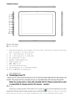
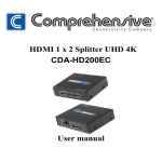
HDMI Matrix 4 x 4 User manual Thank you for purchasing this product. For optimum performance and safety, please read these instructions carefully before connecting, operating or adjusting this product. Please keep this manual for future reference. Introduction HDM-944 is a 4-by-4 DVI/HDMI matrix with 4Kx2K. It allows any source (Blue-Ray player, HD DVD player, satellite receiver, game system, etc.) to be shown on any of four displays simultaneously, no matter the source is HDCP or not. Extra infrared receiver port is supplied for remote control. HDM-944 offers solutions for digital entertainment center, HDTV retail and show site, HDTV, STB, DVD and projector factory, noise, space and security concerns, data center control, information distribution, conference room presentation, school and corporate training environments, etc. Features 1. Supports display resolutions up to 4K x 2K@30Hz,1080P@120Hz,and 1080P 3D@60Hz 1 2. 3D HDMI 1.4a video format support. 3. 3D video support including Frame Packing for all 3D formats up to a 297MHz TMDS clock. 4. Supports deep color up to 48-bit per pixel. 5. HDCP 1.4 support (INPUT), HDCP v1.4a protocol compliant (OUTPUT). 6. Supports the reception of any audio data conforming to the HDMI specification 1.4 such ad L-PCM at up to 192kHz,compressed audio(IEC 61937),DSD,DST,DTS and HBR. 7. Full colorimetry including sYCC601, Adobe RGB,Adobe YCC601,xvYCC extended gamut color. 8. Operates for TMDS clock frequencies up to 300MHz. Package 1. HDMI Matrix ------------------------------------------------------------------------------------ 1PCS 2. 12V2A DC Power Supply Adaptor ----------------------------------------------------------- 1PCS 3. Operation Manual ------------------------------------------------------------------------------- 1PCS 2 4. Remote Controller---------------------------------------------------------------------------------1PCS Specifications 1. Frequency Bandwidth 2.97Gbps 2. Input Ports 4 x HDMI Female input ports 3. Output Ports 4 x HDMI Female output ports 4. Power Supply DC 12V 2A 5. ESD Protection Human Body Model: ± 8kV (air-gap discharge) ± 4kV (contact discharge) 6. Dimensions (mm) 113(W) X 260 (D) X 26 (H) 7. Weight(g) 750 8. Operating Temperature 9. Storage Temperature -20°C ~ 60°C / -4°F ~ 140°F 10. Relative Humidity 20 ~ 90% RH (Non-condensing) 0°C ~ 40°C / 32°F ~ 104°F 3 11. Power Consumption (Max) 20W Operation Controls and Functions Front Panel 1. ON/OFF: Power on/off switch. 2. POWER: This red LED illuminates when the device is connected with power supply. 3. IR IN: Remote control signal receive. 4. OUTPUT A: Press this button to select the input source to HDMI OUTPUT A, and these red LED illuminate when the output select to the corresponding input. 5. OUTPUT B: Press this button to select the input source to HDMI OUTPUT B, and these red 4 LED illuminate when the output select to the corresponding input. 6. OUTPUT C: Press this button to select the input source to HDMI OUTPUT C, and these red LED illuminate when the output select to the corresponding input. 7. OUTPUT D: Press this button to select the input source to HDMI OUTPUT D, and these red LED illuminate when the output select to the corresponding input. Rear Panel 1. INPUT PORTS: LED1-4 illuminate when the HDMI signal plug in INPUT 1-4 port. INPUT 1-4 ports are where you connect the HDMI source. 5 2. OUTPUT PORTS: LED A-D illuminate when the TV plug in OUTPUT A-D ports. OUTPUT A-D ports are where you connect the HDTV or monitor with HDMI cable 3. RS232: This port can control the matrix via PC. 4. DC 12V: Plug the 12V DC power supply into the unit and connect the adaptor to AC wall outlet. Application Example 6 Remote control 7 OUT A: Press 1\2\3\4 button will fast switch to select input source to HDMI OUT A, and the LED will indicate the corresponding input source. OUT B: Press 1\2\3\4 button will fast switch to select input source to HDMI OUT B, and the LED will indicate the corresponding input source. OUT C: Press 1\2\3\4 button will fast switch to select input source to HDMI OUT C, and the LED will indicate the corresponding input source. OUT D: Press 1\2\3\4 button will fast switch to select input source to HDMI OUT D, and the LED will indicate the corresponding input source. 8 Matrix controller user guide Installation Matrix controller is a green software. Just copy MatrixController.exe to PC which is used to control the Matrix by RS232 COM port to complete installation. Preparation 1. Connect PC and Matrix by RS232 cable (headers of both sides of cable should be FEMALE) 2. Power-up Matrix 3. Double click MatirxController.exe icon to run it Introduction “General” Page: 9 ① ② ③ ④ Control mode select: Only COM control mode supported. Select RS232 COM port. Click to connect or disconnect PC and Matrix. Click to refresh device status: include device information displayed in 10 ⑧ area and Input/Output settings ⑤ To enable or disable Input/Output tags displaying when setting buttons on “Setting” page focused. ⑥ ⑦ Click to select page Status bar: RS232 COM port connection Communication status Prompt of operation messages Time and Date ⑧ Device information display area “Port Tag” page 11 ① Input port tags. ② Click to edit Input port tags. ③ Output port tags. ④ Click to edit Output port tags. 12 Edit Input port tags: After action of ②, edit form will pop-up as below: Define tags for respective Input port, then devices connect the Input ports can be easily remembered. Click buttons with “×” caption to delete tag which is no use any more, if tag is still used by any other Input port, delete action will be discarded. Edit Output port tags: 13 After action of ④, edit form will pop-up as below: Define tags for respective Output port, then displays connect the Output ports can be easily remembered. Click buttons with “×” caption to delete tag which is no use any more, if tag is still used by any other Output port, delete action will be discarded. “Setting” page 14 ① ② ③ ④ ⑤ LED which display Input number for respective Output. Click to select Input port for respective Output port. Click to select previous or next Input port for respective Output port. Display Input to Output with tag information when mouse moves over Pre-Setting items. 15 ② buttons. ⑥ ⑦ Click to edit selected pre-setting item. Set selected pre-setting item to Matrix. Edit selected pre-setting item After action of ⑥, edit form will pop-up as below: 16 ① ② ③ Pre-Setting name Select Input for respective Output Set all Output ports from same Input “EDID control” page 17 ① Set EDID mode for selected Input port or All Input ports, click “Set” button to complete action. “Auto EDID mode” can only be set for “All Inputs”. ② Copy EDID from Output port to selected Input port or All Input ports, click “Copy” button to complete action. ③ ④ ⑤ ⑥ Read EDID content from Output port and display in grid, click “Read” button to complete action. Save EDID content which displayed in grid to binary file (file extension is “.bin”) Open EDID binary file and display in grid Download EDID content which displayed in grid to selected Input port or All Input ports, click “Download” button to complete action. ⑦ ⑧ EDID content displaying grid Click to clear EDID content displayed in grid “Advanced” page 18 ① Enable and disable IR control. ②③④ TCP Mode do not support. “FW upgrade” page 19 ① Firmware upgrade is not supported. 20