1
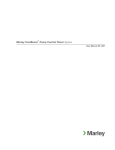
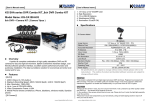
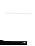
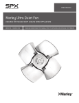
/ Marley Liquid Level Control System /
User Manual 98-1482A
1
Contents
Introduction.............................................................................................. 2
Wiring....................................................................................................... 3
Operation.................................................................................................. 4
Troubleshooting........................................................................................ 8
Checkout Procedure—Water Makeup and High Alarm............................ 9
Checkout Procedure—Low Alarm.......................................................... 10
Replacement Parts................................................................................. 11
Specifications......................................................................................... 12
Introduction
The Liquid Level Control systems are used to accomplish several functions:
•Electronic Water Makeup
•Low-water Alarms
•Low-water Cutoff
•High-water Alarms
•High-water Cutoff
The most common application is electronic water makeup. This system
is used with a remotely installed water solenoid valve to add water to the
system as required. Conductivity probes are utilized to electronically monitor
the water level. Problems associated with freezing water lines are avoided
in a properly designed system by installing all pressurized water lines in a
protected environment. Makeup water is added to the cooling system and
supplied to the tower through non-pressurized, self draining lines.
Low-water and high-water alarms can be utilized to give warnings associated with abnormal operating conditions. The system provides dry
contacts to interface with digital control systems or user supplied alarm
indicators to signal when corrective action is required.
Low-water cutoffs are commonly applied to protect pumps and basin
heaters from operating without water thus preventing costly repairs associated with unintended operation. Dry contacts can be wired directly in
series with pilot duty controls or to digital control systems to initiate the
shutdown of protected equipment during low-water situations.
2
Wiring
Make-Up
Relay
H
L
15
14
C
13
Terminal Strip Legend
Connection for Outgoing Lines
1
2
3 and 4
3
Note 5
4
2
1 and 2
1
5
6
High
Relay
H
L
16 or 17
C
13
7
8
9
5 and 6
10
11
7 and 8
Note 5
12
2
1 and 2
1
H
L
18 or 19
C
13
9 and 10
Note 5
2
1 and 2
1
Make-Up
Relay
H
L
15
14
C
13
SOL
1
High Level Cut-Off
Low Level Alarm
Low Level Cut-Off
13
Reference Probe
14
Make-Up On Probe
15
Make-Up Off Probe
16
High Alarm Probe
17
High Cut-Off Probe
18
Low Alarm Probe
19
Low Cut-Off Probe
Note
Diagram shows internal wiring.
2
One relay is required for each alarm or cutoff level.
2
3
Ground screw is provided on the relay panel.
1
4
Relay cards provide dry contacts. Power for alarm signals
or solenoid valves must be supplied externally.
5
10 amp resistive load or (1/3 hp @ 120V AC)
3
115VAC
High Level Alarm
1
4
2
Water Make-Up
Connection for Probe Wiring
Low
Relay
11 and 12
115 VAC
Note 5
115 VAC solenoids
connected as shown
3
Operation
The Liquid Level Control System consists of special purpose liquid sensing relays connected to a probe assembly located in the cold water basin.
The relay cards are powered by a 115 VAC power supply. The relay cards
produce a current limited 17.5 VDC signal to detect water level. This current is conducted through the water across probes of dissimilar length.
When the water level reaches the shorter probe, the circuit is completed
and the relay responds, opening or closing relay contacts corresponding
to a fixed level.
The longest probe is the ground reference probe, and is shared by all the
functions of the system. For low level control, the ground reference probe
and a slightly shorter probe provide the circuit. The distance from the tip of
this probe to the floor of the basin determines the minimum water level that
is allowed before an alarm is produced or pump operation is interrupted.
See Figure 1. When the water level drops below this level, the connection
between these probes is broken and the relay contacts transfer.
5611
Low Signal
115 VAC
H
L
C
NC
NO
C
AC
Min. Depth
Figure 1
Fill control utilizes two additional probes. The longest of these two probes
determines the level at which fill begins, and the shorter probe determines
the point at which fill is complete. The fill valve opens when the water
level drops below the longer probe, breaking contact between it and the
ground reference. The fill valve remains energized until the water level
reaches the shorter probe, completing the circuit across this probe and
the ground reference. See Figure 2. At this point, the valve is de-energized
and closes.
4
Operation
5612
H
L
C
NC
NO
C
Valve
Circuit
115 VAC
AC
Complete
Fill Start
Figure 2
The high level alarm is provided by the shortest probe and provides warning
that the water level is exceeding the proper operational level. This alarm
signal is produced when the water makes contact across the shortest
probe and the ground reference, and ceases when the water level drops
below this level. See Figure 3.
5612
High Signal
115 VAC
NC
NO
C
H
L
C
AC
High
Normal
Figure 3
5
Operation
All the probes are contained in a single assembly and protected by a sheet
metal stilling chamber. The probe assembly is connected to a bracket for
mounting in the cold water basin. See Figure 4. All wires are routed to
the relay enclosure in a liquid tight conduit.
Conduit to be routed so relay box is high point in system and probe holder
is low point.
Each function, low alarm, water makeup or high alarm, requires a separate
relay. All relays are powered by a 115 VAC supply voltage connected to
terminals labeled “AC line” on the terminal strip at the bottom of the relay
circuit board. Terminals COM, NO and NC provide outputs to alarms or
fill valves. Terminals C, L and/or H on the terminal strip at the top of the
relay circuit board are connected to the probes. See Figures 1, 2 and 3.
Figure 4
6
Operation
For a single function system requiring only one relay, the relay is housed in
a 6″ x 6″ NEMA 4X enclosure normally mounted on the side of the cooling
tower. For two or more functions, relays are located in a 12″ x 14″ NEMA
4X enclosure and all relay wiring is connected to terminal strips located
in the enclosure. See Figure 5.
AC
H
L
C
High Alarm
NC
NO
C
AC
NC
NO
C
H
L
C
Water Makeup
Low Alarm
AC
NC
NO
C
H
L
C
High Cutoff
or
Low Cutoff
1 2 3 4 5 6 7 8 9 10 11 12 13 14 15 16 17 18 19
Figure 5
AC
Power
To
Outputs
To
Probes
There are two types of relays used in the system. The two relays appear
exactly alike and are identifiable only by the numbers printed on the circuit
board. The relay used for low level control is designated TYPE 5611-0000
and is described as direct operation. This means that when power is
applied to the relay, the contacts remain in their normal position until the
probe circuit is completed across C (ground reference) and L (low) at which
time the contacts transfer.
The relay used for fill control and high level alarm is designated TYPE
5612-0000 and is described as inverse operation. The contacts operate
the opposite of direct operation, transferring when power is applied to the
relay and returning to their normal position when the probe circuit across
C and H is completed.
7
Troubleshooting
Trouble
Probable Cause
Remedy
Tower Basin Overflows
1. Faulty Sol. Valve
2. Faulty Fill Relay
(See Checkout Procedure.)
3. Deposits (Plating) on Probes
4. Low Liquid Conductivity
(de-mineralized water, etc.)
1. Faulty Sol. Valve
2. Faulty Fill Relay
(See Checkout Procedure.)
3. Contamination (foam) in Stilling
Chamber
1. Contamination (foam) in Stilling
Chamber
1. Replace Valve.
2. Replace Relay.
Low Water Level
Low Level Alarm Fails
False High Water Alarm
False Low Water Alarm
1. Contamination (foam) in Stilling
Chamber
2. Faulty High Alarm Relay
(See Checkout Procedure.)
1. Faulty Low Alarm Relay
(See Checkout Procedure.)
3. Clean Probes.
4. Contact Marley.
1. Replace Valve.
2. Replace Relay.
3. Clean Stilling Chamber.
1. Clean Stilling Chamber.
1. Clean Stilling Chamber.
2. Replace Relay.
1. Replace Relay.
Note: Checkout procedure for relay circuit boards is provided on pages 9 and 10.
8
Checkout Procedure
5612-0000 Relay — Water Makeup and High Alarm Circuits
0
H
Load
Contacts
NC
L
NO
C
COM
115 VAC
0
H
Load
Contacts
Probes
NC
L
NO
C
Probes
COM
115 VAC
AC Line
AC Line
Step1
Step 2
1—Disconnect all wires from relay card. Connect power
to the relay.
1. Attach a jumper to C and L (probe terminals). Meter
should still read 0 ohms.
2—Connect ohmmeter across contacts COM and NO.
Meter should read 0 ohms (closed contact).
H
infinity
Load
Contacts
NC
L
NO
C
COM
115 VAC
0
H
Load
Contacts
Probes
NC
L
NO
C
COM
115 VAC
AC Line
Probes
AC Line
Step 3
Step 4
1. Touch a jumper to the H and C terminals. Meter
should read “infinity” (open contact).
1. Remove the jumper from L to C. Meter should read
0 ohms, indicating contacts have closed.
2. Remove the jumper from H to C, leaving the jumper
from L to C in place. Contacts should remain open.
Note—Check out procedure for 5212 relay uses
normally open contacts, verses normally closed for
5611. See page 10.
9
Checkout Procedure
5611-0000 Relay — Low Alarm Circuit
0
H
Load
Contacts
NC
L
NO
C
COM
115 VAC
0
H
Load
Contacts
Probes
NC
L
NO
C
Probes
COM
115 VAC
AC Line
AC Line
Step1
Step 2
1—Disconnect all wires from relay card. Connect power
to the relay.
1. Attach a jumper to C and L (probe terminals). Meter
should still read 0 ohms.
2—Connect ohmmeter across contacts COM and NC.
Meter should read 0 ohms (closed contact).
infinity
Load
Contacts
H
NC
L
NO
C
COM
115 VAC
0
H
Load
Contacts
Probes
NC
L
NO
C
COM
115 VAC
AC Line
Probes
AC Line
Step 3
Step 4
1. Touch a jumper to the H and C terminals. Meter
should read “infinity” (open contact).
1. Remove the jumper from L to C. Meter should read
0 ohms, indicating contacts have closed.
2. Remove the jumper from H to C. Contacts should
remain open.
Note—Check out procedure for 5211 relay uses
normally closed contacts, verses normally opened
for 5612. See page 9.
10
Replacement Parts
1
2
5
AC
NC
NO
C
AC
H
L
C
High Alarm
AC
H
L
C
Low Alarm
NC
NO
C
4
NC
NO
C
H
L
C
Water Makeup
High Cutoff
or
Low Cutoff
3
1 2 3 4 5 6 7 8 9 10 11 12 13 14 15 16 17 18 19
1—4 x 4 Box Cover...................................................................................................... C32349D
2—4 x 4 Gasket............................................................................................................ C32350D
3—Sensor..................................................................................................................... C745160
4—BW Relay 5611-0000, Low Alarm or Low Cutoff.................................................... A87493D
5—BW Relay 5612-0000, High Alarm, High Cutoff or Makeup................................... A87492D
11
Specifications
.187" SLOT, 2 PLACES
4.0"
3.87"
3.16"
1.5"
3.0" PC BOARD
1.25"
Series 56 Relay
1.72"
PVC SNAP-IN MOUNTING TRACK
NET WEIGHT 7.25 OUNCES
Voltage: 120 Volts AC, 50/60 Hertz 240 Volts AC, 50/60 Hertz.
Other voltages available on special order.
Power Required: 4 Volt-amperes, 2 watts.
Load Contacts: Single pole, double throw. Gold-flashed silver cadmium
oxide.
Contact Ratings: 10 amperes resistive load or 1/3 hp at 120 Volts AC; 6
amperes resistive load at 240 Volts AC or 28 Volts DC.
Sensing Circuit: 17.5 Volts DC open circuit; 400 microamperes short
circuit. Includes a lock-in feature for greater versatility.
Sensitivity: 50,000 ohms/cm fixed is standard. Other sensitivities, fixed
or adjustable, are available on special order.
7401 WEST 129 STREET | OVERLAND PARK, KANSAS 66213 UNITED STATES | 913 664 7400 | [email protected] | spxcooling.com
In the interest of technological progress, all products are subject to design and/or material change without notice.
©2009 SPX Cooling Technologies, Inc. | Printed in USA
Manual 98-1482A