1
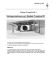
Weibel Lift AG
Weibel Projector lift II
Installation Manual for the Weibel Projector lift
Congratulations on choosing a world class product.
This detailed assembly manual will help you to assemble the device correctly.
Please take the time to read through the instructions carefully.
Warning
Never touch the moving lift with your hands or any other limb.
Areas of particular danger such as chains or chain pinions, between moving parts or between moving ceiling
elements and ceiling must be avoided. Never work on a moving lift. Disconnect from the mains if you
want to work on the lift.
2
Contents
Dimensions
4
Technical Data
6
Preparation
Building work
7
In the workshop
7
Installation
9
Emergency release
13
Maintenance
14
Connections and controller
15
Circuit diagram
18
User Manual for the customer
19
3
Dimensions
Bottom View
Top view
4
Dimension
Left View
Side View
Series Professional
max. Projector
dimensions(Wx H x D) in
mm
Ceiling recess
(L x D x H) in mm
Max load.
Professional 180 PL2
Professional 230 PL2
Professional 290 PL2
Professional 350 PL2
445 x 130 x445
445 x 180 x 445
445 x 210 x 445
445 x 270 x 445
835 x 540 x 180
835 x 540 x 230
835 x 540 x 290
835 x 540 x 350
35 kg
35 kg
35 kg
35 kg
Series XL
max. Projector dimensions
(W x H x D) in mm
Ceiling recess (L x D x H) in
mm
Max load.
XL 290 PL2
XL 350 PL2
XL 420 PL2
XL 500 PL2
575 x 210 x 500
575 x 270 x 500
575 x 360 x 500
575 x 420 x 500
965 x 540 x 290
965 x 540 x 350
965 x 540 x 420
835 x 540 x 500
35 kg
35 kg
35 kg
35 kg
Dimensions
A
B
C
D
E
F
I
K
L
M
N
O
Professional
406
200
580
355
510
715
450
540
445
484
295
395
XL
406
200
710
355
640
845
580
670
575
614
295
395
Installation
height
G
H
Travel
range
Travel
time
180
230
290
350
420
500
220
270
360
410
460
540
160
210
280
340
410
490
115
165
225
285
355
435
12 sec
16 sec
22 sec
27 sec
32 sec
38 sec
Custom made lifts with specifically adjusted
spindle lengths with maximum travel of 420 mm
can be used without problems
We reserve the right to make technical changes
5
Technical Data
Drive
Electrical spindle drive with circuit breaker
Operating voltage
primary 85 - 265 V 50 - 60 Hz, secondary 24 V DC
Power consumption
max 1.3 A
Connection
Terminal clamp
Controller
2 floating contacts (normally open) terminal clamp, RS-232
Protection type
IP22
Notional operating life
ED 20%
Temperature range
0° C to +70° C
Running time
See values in table
Lock protection
electronic
Crush Protection
mechanical
Max. weight of ceiling panel
10 Kg
Design
Steel construction, folded and welded
Colour
RAL 7001
External dimensions
See value in table
We reserve the right to make technical modifications
6
Building preparation
If the lift is fitted into a ceiling recess, please note the
following: The surface of the ceiling recess must be
smoothly plastered and painted. No particles of concrete
may fall onto the lift. The installation surface on the ceiling
must be even. The required cables (VGA, Video, S-Video,
HDMI, control cable) must be run in. They should protrude
around 1.5 m from the tube. A 2-plug 230V AC socket
must also be fitted and connected in the space provided.
This must be connected so that it can be easily switched
off via a main switch.
Projection direction
This has the following benefits:
- The projector cannot be accidentally switched on behind the ceiling for long periods, thus saving on lamp
life.
- The system does not consume unnecessary standby power.
- If the motor needs to be reset, the main switch is switched off for 30 seconds = Controller Reset.
Check whether the ceiling closure panel fits into the recess, (1 to 2 mm ventilation gap each side). Grinding
the recess again when the lift has been installed is not recommended due to the build-up of dust near the lift.
In the workshop (Preparation work)
Before installation
Open
Close
Service position
Place the lift on a clean surface (with the installation side facing down)
and plug the power cable into a 230 Volt socket. If you cannot find
any defects or transport damage, extend the lift for the first time with
the help of the buttons on the circuit board.
For the next step, the lift must be fully retracted.
Fitting the projector onto the rapid change tilting mount:
You can mount the projector in one of 2 possible directions: (diagonal
projection so that the limit switch with the cylinder is behind the projector or lengthwise projection with the
drive behind the projector. The second variant must be discussed before ordering the tilt mount).
We recommend using diagonal projection when possible.
Now take the supplied cardboard template for fitting the projector onto the tilt mount.
Remove the rapid change panel and insert the cardboard template into the tilt mount.
Knurled screw on tilt mount:
To remove the projector plate, simply remove the knurled screw by hand. This enables speedy assembly.
(The 2 Philips head screws are factory fitted and may only be loosened if the projector plate has to be moved
to the side.)
7
Now position the projector so that the lens is, if possible, close to
the front edge (projector screen side) of the lift frame (approx. flush
with the moving platform outer edge). This is the correct position for
proper projection of the full image. The projector should always be
upside down if fitting it to the ceiling! Using a pencil, mark the back
edge and the side position of the projector on the cardboard
template. Remove the cardboard template from the tilt mount. Now
transfer the 2 to 4 mounting holes from the underside of the
projector onto the template:
To mark out the mounting holes onto the cardboard template, it is
best to use a sheet of transparent plastic. This is placed onto the
base of the projector and the holes and positioning marks marked
onto it. This is then placed onto the cardboard template and the markings are traced on with a pencil. Make
holes of approx. 5 – 6 mm in the template and mount the projector onto them.
Now you can fit the projector with the cardboard template onto the tilt mount and check the position of the
projector. If the projector is correctly positioned, you can transfer the holes onto the metal plate.
Now drill holes 5 to 6 mm in diameter into the metal plate.
Attention: Drill the holes on the correct side of the panel.
To attach the projector to the plate, use the supplied flat head screws
which you have shortened (small plastic tubes as washers).
Attention: The screw heads must not protrude through the plate
Countersunk
screws
The screws must not protrude more than 6
– 8 mm from the washers which were put
onto the plate. If your projector has vent
holes on the bottom, sufficiently long
washers must be placed in between to
ensure good ventilation.
Fit your projector with the rapid change tilt mount into the
projector lift to test it. Check that it does not touch a spindle or
moving parts of the lift at any point. Make sure that the objective
does not protrude above the lift frame, but comes to rest as close
as possible to the platform edge (take into account any
mechanical zoom/focal length). Fully retract and extend the lift. In
doing so, the projector must not touch any spindle or moving lift
parts.
Attention: make sure that there is space for the cable
connections! Minimum gap between projector and spindle is
approx. 5 mm!
Using the rapid change plate, remove the projector so that the tilt mount remains mounted to the lift. Fully
retract the lift again and disconnect the mains cable. Keep the lift in the original packaging so that it is
protected against drill dust.
8
Fitting into the installation space
4 mounting holes are marked on the ceiling using the supplied
cardboard template. The template must be set against the walls of
the recess on the two indicated sides. Follow the instructions on the
template carefully! Drill holes 30 to 35 mm deep, 8 mm in diameter!
Leave lift in original packaging so that it is protected against dust
during the next phase of drilling holes into the concrete. Make sure
there is no dust on the lift at any time during assembly and ceiling
construction.
Cover the spindles for added protection!
Mounting material must be used to suit existing conditions at the
installation site and to meet the regulations applicable to the site.
.
230 V
230 V
Steckdosen
22plug
sockets
ca.
ca.115
115
540
M40 Rohr
M40
tube
Concrete
Betondecke
ceiling
M20 Rohr
M20
tube
Nische
Recess
Metallwinkel
Metal
bracket
200
140
Sichtbare
Decke
Visible
ceiling
VGA- and Video cable
Control cable to up/down switch
Plug socket 2 x 230V
Metal bracket
9
Installation into a false ceiling with a large ceiling space
Threaded rods M 8 (or M 6)
The centre point between the two standing
board corresponds to the distance between the
mounting holes of the ceiling lift (see cardboard
template).
When fastening to the ceiling, washers as well
as a nut tightened to a max. 4 Nm with a
suitable tool should be fastened to the threaded
rods.
Screw (threaded
rod)
2 Boards:
Length:
Thickness:
Height:
600 mm
40 – 50 mm
The false ceiling height minus
Lift height minus ceiling panel
minus approx. 30 mm
This construction is very stable.
The ceiling lift:
It is fitted in the same place as it would be if it
were fitted directly to the ceiling.
.
10
The retracted projector lift (with the fitted tilt mount) is now fitted
onto the ceiling. The lift must be positioned in such a way that
the 3 stop bars at the side and the front of the frame are snug up
against the edge of the recess. This ensures that the ceiling
closure panel fits. The rubber pads on both sides of the lift frame
reduce any sound transmission to the structure of the building.
The frame is screwed on with a 10 mm socket using the supplied
washers, spring washers and steel hex screws (M6 x 25 mm).
Do not over tighten the screws, since this may displace the
rubber and operating vibrations may be transmitted to the
building.
Stop bars
Important: If the motor gradually runs tighter when running it in, the 4 ceiling screws are already too tight.
Loosen the 4 screws slightly until the lift runs easily and smoothly to its full height.
The mains supply is connected and the lift can be operated on the ceiling for the first time. The top of the
moving platform is now clean and free of parts such as screws, keys etc. Ensure that no control or mains
cable touches the chain or can become trapped. When fully extending and retracting, take care that nothing
is scratched or trapped (never put your hands or other limbs close to moving lift parts when the lift is
moving).
After successfully extending and retracting, the projector (with the quick change panel) is again fastened to
the lift and switched on. It is pointed at the projector screen.
For side adjustment, the 2 mounting screws at the top on the platform are loosened slightly using a 10 mm
socket, so that the tilt mount can be turned. Tighten these
screws again after adjustment.
The tilt, as well as the horizontal positioning, is adjusted by
loosening the 4 socket head screws on the side of the tilt
mount:
Firstly tighten them just slightly with a 4 mm Allen key. Switch
off the projector, leave to cool down and remove. Now tighten
the 4 socket head screws on the tilt mount. Then the 2
supplied plastic cover plates are fitted flush with the 2 large
pilot holes on the lift and pressed on securely.
Extension lock / Controller reset:
This projector lift is fitted with a contactor control against overextending.
11
Since the ceiling will soon be closed up, mains and control cables must be connected next to the motor in
such a way that they never become trapped or get into the chain. Plug in all cables on the projector and on
the lift controller. Tighten all threaded connectors!
If the clip is not already fastened to the platform in the correct place, put
it into the hole which is best situated for routing the cable (4 mm Allen
key).
Various holes are provided on the platform for this purpose. The cables
are neatly bundled and fastened to the platform with several cable ties
so that the cables running from the projector run against the top of the
projector. A hole for the plastic anchor plug is drilled into the recess (6
mm) around 20 - 30 cm from the fixture point on the lift and is fitted with
the wood screw (4,5 x 80 mm). The cables are fastened to the platform
a second time so that a large and free loop is formed, which is neither
blocked, pulled tight or trapped at any point. Conduct a test first by
temporarily fastening the cables. It is usually possible to route the loop
in such a way that the control plug is suitable as the 2nd fixture point on
the controller housing. In this case, another hole does not need to be
drilled (avoid build-up of dust or hold a box between lift and drill!).
The height of the ceiling bracket on the lift can now be
adjusted to the ceiling. Loosen the M4 hex screws! The
ceiling panel which acts as the „moving element“ is now
adjusted so that there is a ceiling gap of around 1 -2 mm
around the panel. The ceiling panel can be positioned
accurately thanks to the 4 broad slotted holes. Make sure that
the projector with the tilt panel is positioned relatively
close to the ceiling panel (below), so that the full image
height is free for projecting.
Use the slotted holes in the tilt mount or additional small tubes or washers between the platform and tilt
mount to help you with this.
After successful positioning, all 4 corners of the moving panel
can be fitted to the height of the finished ceiling. This is done
using the hex screws on the 4 corner brackets. Gently secure
the panel so that is protrudes slightly, then move the lift up
and push gently under the 4 brackets, until the panel is flush
with the ceiling. Then move the panel down and tighten the
M4 hex screws.
Note on HOME projector lifts:
We recommend that you only use the supplied metal ceiling panel wherever possible. This helps it to blend in
seamlessly with the rest of the ceiling. It is coated with white primer and can be painted in the required colour
after gentle sanding.
12
Controls:
We recommend that you use the following options as projector lift controls:
- A simple up/down wall switch: latching up/down switch,
as used with venetian blinds, electric screens, etc.
Important: Never supply the control terminal with mains voltage or external voltage!
Custom accessories:
-Media controller (e.g. AVIT, RTI, AMX, Crestron etc.):
Use 2 Relays (or changeover switch in emergencies) (isolated).
Media controller with RS-232 controller, a suitable connection (SubD9) is available
The control terminal only needs terminals for 24 Volt DC / 0,1 Amp. (low current).
Do not make modifications to this lift and the control electronics.
Should you have any special requirements, we would be happy to assist.
Important:
Never open the control unit, motor and drive mechanism.
The chain tension does not have to be adjusted.
If the seals are no longer in their original condition, the liability and warranty shall be
deemed null and void.
In the event of an emergency contact the manufacturer before working on the device.
Disassembling the ceiling panel in case of emergency
If the retracted lift does not extend even after resetting (disconnect from mains for at least 30 seconds) due
to a lightning strike or an unforeseeable fault, then it can be released using the emergency release:
The cords are used to release the mounting brackets.
When assembling the lift, route these cords close to the edges of the ceiling panel so that they are easily
accessible in case of emergency.
The springs have a travel of 40 mm – move the ceiling panel down within this range with a suitable tool and
release the mounting brackets by pulling on the cord.
13
Maintenance:
To prevent any operating noise, the spindles should be lubricated after every 10 to 20
years: Fully extend the lift. Now cut the power supply for your own safety. Always use
Molykote 33 light grease and a small hard bristle brush. Brush the grease on
horizontally into the spindle thread above the plastic nuts using the brush (put a small
amount of grease onto the brush and brush in well). Do not lubricate underneath the
plastic nut. Move the lift up and down a few times. This automatically distributes the
grease to all parts.
Never use the grease brush on the lift when in operation
(disconnect from the mains at the main switch or fuse)!
The chain must not be lubricated or oiled! Re-tensioning is not necessary since the chain
will still continue to work properly if it is a little slack.
If the chain becomes stretched over the years it can be re-tensioned as follows:
Loosen screws
Re-tension the chain
In principle, the lift should operate for many years without the need for maintenance.
14
Weibel Lift AG
WEIBEL PROJECTOR LIFT
Projector Lift Connections
1. 90 – 240 VOLT supply (incl. projector supply)
A 2 or 3 plug socket (one phase) must be fitted next the
projector lift on the ceiling. For safety and reset purposes,
as well as to switch off the standby power for the lift
controller, you should be able to switch off the lift
controller and projector via a main switch. This switch
should be located in the same room if possible.
Use a 6 Amp fuse.
If you have a false ceiling, this plug socket can be fitted anywhere approx. 0.3 m
from the ceiling recess. (No cable ducts should be laid in the installation area of the
projector lift!)
If fitting the lift directly into a concrete ceiling (encased), the 2 or 3-plug socket must
be fitted exactly according to the steps on our special assembly plan AP. In
addition, the 3 supply ducts must be fitted according to the details on the assembly
plan and in the diameters specified hereby.
15
2. Up/Down switch
a)
MANUAL CONTROLLER
An external UP/DOWN switch (isolated) is
needed. The 24V DC coming from the lift
controller activates the switch.
No external voltage is needed!
b)
BUS and MEDIA CONTROLLER
Use 2 relays!
DOWN terminals
UP
terminals
TX
RX
Bu
0V
c.)
Controller with RS232
Protocol settings:
9600,8,n,1, local echo on, no flow control
Sub-D 9 (F)
Commands
All commands ( except +-) must be executed by [Enter].
Correct commands are confirmed by „Ok“,
incorrect ones by „Fault“.
All commands are not case sensitive.
Open [Enter]
Lift opens to the set opening point
Stop [Enter]
Lift stops
Close [Enter]
Lift closes until limit switch is activated
Service [Enter]
Lift moves to the maximum possible opening point for maintenance purposes.
Adjuston [Enter]
Activates adjusting mode for the opening position. Using + or – you can now fine adjust the position by
increments of approx. 1 mm
if the required position has been reached, first press [Enter].
Only then can the action be completed. And:
Adjustoff [Enter]
Closes adjusting mode and permanently saves the new position. The function can also be used if you have not
adjusted anything. It always saves the current position of the lift as a projection position.
Adjusting the projection opening position
Use the „Up“ or „Down“ buttons to move the lift close to the position required. The „Adjuston“ command
activates adjusting mode in which you can adjust the position by millimetres using + or –. When the optimum
position has been found, confirm with [Enter] and then exit adjusting mode using the command „Adjustoff“. The
position is then permanently saved.
Re-calibration
Keep the „Up“ and „Down“ buttons pressed when switching on.
The lift then re-calibrates itself to the limit switch by opening and closing 1 – 2 times.
(The max. opening point does not change)
16
Circuit diagram
Open
Close
Service position
Limit switch
Hall sensor
Bu
Sub-D 9 (F)
Service position
Motor
On
Off
Thank you for reading this installation manual.
A lift is subject to strict safety regulations.
This product complies with all requirements.
This is also subject however to correct assembly and installation.
Weibel Projector Lifts are tested and meet all corresponding safety regulations.
We hope that this manual will help you to successfully install your device.
WEIBEL LIFT AG
17
Weibel Lift AG
TO BE READ BY THE LIFT USER
WEIBEL PROJECTOR LIFT
User Manual
This projector lift is a first class product which allows only a very small ceiling gap thanks to its excellent return
accuracy. All this however depends on compliance with the following safety instructions:
Warning
Never touch a moving lift with your hands or other limbs. Areas of particular danger such as chains or chain
pinions, between moving ceiling elements or between moving parts and ceiling panel must be avoided. Never work
on a moving lift.
Modifications or alterations to this lift may not be carried out by unauthorised persons. If such requests are made,
contact your projector lift installer.
When working on areas around the chain or control box, you must disconnect the power supply and ensure that no
one can inadvertently reconnect it.
Never raise the lift if an additional cable, (i.e. PC cable) is directly connected to the video projector.
When raising the lift, always make sure that no cable protrudes through the moving part of the projector lift or
through the ceiling panel at any point.
Only trained staff should take down the video projector. This applies in particular to changing the lamp or cleaning
the filter.
No other devices may be placed on the lift platform.
The secured cables in the ceiling space must not be unfastened,
since otherwise cables may become trapped.
Chain and chain sprocket must not be lubricated or oiled.
If you hear the spindles chatter at a later point, you may need to lubricate the lifting spindles. Request special
grease from your projector lift installer together with the lubrication instructions or ask your installer to carry
out
the work..
18
Raise the projector lift
Ensure that the video projector fan is not running, or preferably make sure that the lamp is fully cooled down
(approx. 10 minutes).
Set to switch to Up (UP) and check that the lift rises without resistance. At the top, it adjusts itself (using the preset
limit switch) into the correct position (flush with the ceiling). Then switch off at the main switch. Should a problem
arise when raising the lift, immediately switch off at the main switch and have the fault checked / repaired.
Important: Your projector lift has built-in safeguards to prevent it from moving too far down. Consequently
however, if the lift is fully extended, you must firstly fully retract it before you can extend it again.
Standby main switch
If your device is equipped with a main switch, it should be switched off if the projector is out of use for long
periods.
This has the following benefits: - The projector cannot be inadvertently switched on behind the ceiling. This also
saves on lamp usage.
- The device does not consume unnecessary standby power.
- Lightning cannot damage either the lift or projector.
Important:
If the mains cable is damaged, it may only be replaced by an authorised specialist. It must be replaced by an
original cable. Please contact your projector lift installer.
For technicians:
You must lower the lift before it reaches its top limit
(e.g. if the ceiling closure panel jams etc.), switch off the main switch for approx. 30 seconds. You can then set
the switch to OFF and carefully switch on with the main switch. The lift then lowers again and the fault can be
repaired.
Take out the projector
Disconnect all cables on the projector only (loosen VGA connector screws).
Unscrew only the knurled screw behind the projector.
Lift the projector out backwards by approx. 2 cm.
Remove the projector from the projector lift from the side without holding the base panel.
Do not loosen the 2 front screws (M5)!
Re: Video projector maintenance
Cleaning the filter: Please follow the corresponding instructions in the user manual for the projector! Your projector
lift installer will be happy to carry out any maintenance work. This also applies to changing the lamp.
Lift does not work (improbable): Contact your projector lift installer.
We hope that you enjoy using your Weibel Lift
19