1
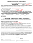
Powerstar Inc
Gaithersburg Md 301-948-0713
Single Phase UPS
External Battery Tray Split Design
External Battery Tray Single Connector
Corporate Offices
9073 Shady Grove Court
Gaithersburg, MD 20877
Ph:(301) 948-0713 Fax:(301) 948-2094
Model: PS3300RM-GDAIS-LCS-R4
Model: PS3300RM-GDAIS-BP
Model: PS3300RM-GDAIS-BP-1
Manufacturing location
1 Linsley Place
Metuchen, NJ 08840
Ph:(732) 494-9491 Fax:(732) 444-9494
www.powerstarinc.com
Revision
Description
Date / Authorized
A
Original release R4
4-6-2011 / PEK
B
Corrected Part number's
4-25-2011 / PEK
C
Updated orderable parts
12-01-11 / PEK
D
Added parts to orderable 5-2-2012 / PEK
parts table (page 15)
Page 1 of 47
4-25-2011
Rev B
Powerstar Inc
PS3300RM-GDAIS-LCS-R4
Single Phase UPS
GUIDE SPECIFICATIONS
1.0 GENERAL
1.1 SUMMARY
This specification defines the electrical and mechanical characteristics and requirements for a
continuous duty single-phase, solid-state, uninterruptible power system. The uninterruptible
power system hereafter referred to as the UPS, will provide high-quality AC power for sensitive
electronic equipment loads.
1.2 STANDARDS
The UPS is designed in accordance with the applicable sections of the current revision of the
following documents. Where a conflict arises between these documents and statements made
herein, the statements in this specification shall govern.
•
•
•
•
•
•
•
•
•
•
•
•
•
•
•
•
•
UL Standard 1778, u-UL
CSA 22.2, No. 107.1
ANSI / IEEE C62.41 Cat A Level 3
IEC 61000-3-2
EN 62040-2
EN61000-4-2
EN61000-4-3
EN61000-4-4
EN61000-4-5
EN61000-4-6
UL1950 / EN6050
FCC Part 15, Class A
ISTA Procedure 1A
RoHs Compliant
MIL-S-901D
MIL-STD-167-1
MIL-STD-1399 Section 300B
1.3. SYSTEM DESCRIPTION
1.3.1 Modes of Operation
The UPS is designed to operate as a true on-line double conversion system in the following
modes:
A. Normal - In normal operation incoming AC power is fed to the input power factor corrected
(PFC) rectifier that converts the AC power to DC power for the inverter. In this mode, power is
also derived from utility power for the battery charger. The inverter derives DC power from either
the PFC rectifier or the battery and regenerates filtered and regulated AC sine wave power for the
connected load. The battery will be charged once the unit is connected to utility power, regardless
of whether the UPS is ON or OFF. In the event of a utility outage or severe abnormality (sag or
swell), the inverter will support the connected load from battery power, until the battery is
Page 2 of 47
4-25-2011
Rev B
discharged or the utility returns; whichever occurs first.
B. Battery - Upon failure of utility / mains AC power, the critical AC load is supplied by the
inverter, which obtains power from the battery. There is no interruption in power to the critical
load upon failure or restoration of the utility / mains AC source.
C. Recharge - Upon restoration of utility / mains AC power, after a utility / mains AC power
outage, the input converter automatically restarts and assumes supplying power to the inverter
and the battery charger to recharge the battery.
D. Automatic Restart - Upon restoration of utility / mains AC power, after a utility mains AC
power outage and complete battery discharge, the UPS automatically restarts and assumes
supplying power to the critical load and the battery charger automatically recharges the battery.
This feature is capable of being disabled by the user.
E. Bypass - The integral bypass performs an automatic transfer of the critical AC load from the
inverter to the bypass source, in the event of an overload, PFC failure, over temperature, DC Bus
over voltage, or inverter failure conditions.
1.3.2 Design Requirements
A. Voltage: Input/output voltage specifications of the UPS are:
• Input: 0 - 140 VAC, 60/50 Hz, single-phase, 2-wire-un-grounded.
• Output: 120 VAC (user configurable: 110V, 115V, 120V, 127V) +3%, 60/50 Hz,
• single-phase, 2-wire-un-grounded.
B. Output Load Capacity: Specified output load capacity of the UPS is:
• 3000 VA / 2700 Watts at 0.9 lagging power factor.
C. Internal Battery: Valve regulated, non-spillable, flame retardant, lead acid cells.
D. Reserve Time: 3000 VA / 2100 watts will be a minimum 5 minutes.
3000 VA / 2700 watts will be a minimum 4 minutes. These times are at an
0
0
ambient temperature of 25 C (77 F) using only the internal battery set.
E. Battery Recharge: The UPS contains a battery recharge rate designed to prolong battery life.
Recharge time for UPS internal batteries is 3 hours to 90% capacity after a complete discharge
into full load.
1.3.3 Performance Requirements
1.3.3.1 AC Input to UPS
A. Voltage Configuration: The UPS operates at these values without drawing power from the
batteries.
120 VAC; single phase, 2 wire ungrounded nominal; variable based upon output loading:
LOAD TRANSFER VOLTAGE
90%
97 VAC
70%
78 VAC
30%
61 VAC
COMEBACK VOLTAGE
104 VAC
85 VAC
68 VAC
Page 3 of 47
4-25-2011
Rev B
B. Frequency: UPS auto senses input frequency when first powered up and will operate within
the following frequency specifications. UPS is capable of Cold Start with default frequency of 60
Hz/ 120 VAC and 208 VAC units and 50 Hz/ 230 VAC. Once started frequency operating window
is 40-70 Hz. There are 3 different frequency settings available in the Liebert GXT3 Configuration
program: Auto frequency sensing (factory default setting), 50 Hz. frequency conversion, and 60
Hz. frequency conversion.
C. Input Power Factor: >0.99 lagging at rated load.
D. Input Current reflected distortion: 5% THD typical.
E. Input Current Ratings:
MODEL PS3300RM-GDAIS-LCS-R4
Input current ratings at full load 24.0A
F. Inrush Current (initial start up, no load): The UPS has a maximum inrush current
of 12 times the full load peak input current.
G. Input Line Transient Immunity: UPS conforms to an input line transient conforming to
IEEE C62.41, Category A Level 3 tests for 120 VAC & 208 VAC models. The 230 VAC models
meet EN61000-4-5.
H. Surge Protection:
MOV ratings are 175 Volt, 80 Joules minimum connected L-N.
1.3.3.2 AC Output, UPS Inverter
A. Voltage Configuration:
120 VAC, 60/50 Hz, single-phase, 2-wire-plus-ground, configuration program
selectable (110V, 115V, 120V, 127V).
B. Voltage Regulation: + 3% steady state.
C. Frequency Regulation: + 5% Synchronized to utility / mains. + 0.1 Hz free running or on
battery operation.
D. Frequency Slew Rate: 1.0 Hertz per second maximum
E. Voltage Distortion: ≤3% total harmonic distortion (THD) typical into a 100% linear load,
≤5% THD typical into a 100% non-linear load with crest factor ratio of 3:1.
F. Load Power Factor Range: The rated load power factor will be 0.9 lagging.
G. Output Power Rating: 3000 VA / 2700 Watts at 0.9 lagging power factor.
H. Inverter Overload Capability: 105% - 125% for 5 minutes, 125% - 150% for 1 minute,
150% - 200% for 2 seconds, and > 200% for 0.25 seconds.
I. Voltage Transient Response: + / - 7% in line mode 0-100-0 % loading of the UPS, + / - 7% in
Page 4 of 47
4-25-2011
Rev B
battery mode for 0-100-0 % loading of the UPS rating.
J. Transient Recovery Time: To nominal voltage within 90 milliseconds.
K. Efficiency: ≥ 89% AC to AC, minimum
1.4 ENVIRONMENTAL CONDITIONS
A. Ambient Temperature:
O
O
O
O
• Operating: -20 C to +50 C (-4 F to + 122 F) for altitudes 0 to 1500 meters
• (0 to 5,000 ft.) above sea level.
O
O
O
O
• -20 C to +40 C (-4 F to + 104 F) for altitudes 1500 to 3000 meters
(5,000 to 10,000 ft.) above sea level.
O
O
• 25 C (+ 77 F) for optimum battery performance
O
O
O
O
• Storage: -20 C to +60 C (-4 F to +140 F) with batteries removed.
O
0
• 20 C (+ 68 F) for optimum battery storage.
The ambient temperature range, when UPS is operational, will be from 0 deg. C
to 25 deg. C. There will not be any degradation in the performance when
operating in this range.
Ambient
Temperature
25-30 deg C
+/- 3 deg C
30-35 deg C
+/- 3 deg C
35-40 deg C
+/- 3 deg C
Max Output
Power Factor
degradation
@ max load
100%-93%
93%-86%
86%-79%
B. Relative Humidity:
Operating: 0 to 95% non-condensing.
Storage: 0 to 95% non-condensing.
C. Altitude:
3,000 m / 10,000 ft. max., without power derating when operated within the temperature specified
in section 1.4.A. ambient temperature will be derated 5° C for each additional 500 meters.
D. Audible Noise:
The audible noise of the UPS will be
<48dBA max @ 1 meter from front and side
<48dBA max @ 1 meter from rear
E. Electrostatic Discharge:
The UPS is able to withstand an electrostatic discharge compliant to ENC61000-4-2.
1.5 USER DOCUMENTATION
The specified UPS system is supplied with one (1) user manual. The user manual includes
instructions, a functional description of the equipment with block diagrams, safety precautions,
illustrations, step-by-step operating procedures, and general maintenance guidelines.
1.6 WARRANTY
Powerstar Inc warrants the UPS against defects in materials and workmanship for two (2)
Page 5 of 47
4-25-2011
Rev B
years.
1.7 QUALITY ASSURANCE
1.7.1 Factory Testing
Before shipment, Powerstar fully and completely tests the system to assure compliance
with the specification. These tests include operational discharge and recharge tests on the
internal battery to assure performance.
The PS3300RM-GDAIS-LCS-R4 is also tested for compliance with UL1950 / EN6050 as outlined
in the General Dynamics documents dated 2-10-2006.
•
•
Dielectric Withstand Voltage Test Procedure for LCS Core Mission Equipment
Ground Bond Resistance Test Procedure for LCS Core Mission Equipment
2.0 PRODUCT
2.1 FABRICATION
All materials and components making up the UPS are new, of current manufacture, and have not
been in prior service except as required during factory testing. All relays are provided with dust
covers.
2.1.2 Wiring
Wiring practices, materials, and coding are in accordance with the requirements the standards
listed in section 1.2 and other applicable codes and standards. All wiring is copper.
2.1.3 Cabinet
The UPS unit is comprised of an input converter, battery charger, inverter, and battery consisting
of
the appropriate number of sealed battery cells; and is housed in a stainless steel rack mounted
chassis
MODEL DIMENSIONS (D x W x H)
PS3300RM-GDAIS-LCS-R4
23.6” x 16.90” x 5.25”
(599.44 mm x 429.26 mm x 133.35 mm)
WEIGHT
Net Weight 115 lbs (52.27 kg)
Shipping Weight 125 (56.82 kg)
2.1.4 Cooling
The UPS is forced air cooled by an (4) internally mounted, continuous fans. Fan power is
provided from the internal DC supply. Air intake is through the front of the unit and exhausted out
the rear of the unit.
2.2 COMPONENTS
2.2.1 Input Converter
2.2.1.1 General
Incoming AC power is converted to a regulated DC output by the input converter for
supplying DC power to the inverter. The input converter provides input power factor
correction and input current distortion reduction.
Page 6 of 47
4-25-2011
Rev B
2.2.1.2 AC Input Current Limit
The input converter is provided with AC input current limiting whereby the maximum
input current is limited to 125% of the full load input current rating.
2.2.1.3 Input Protection
The UPS has built-in protection against undervoltage, overcurrent, and overvoltage
conditions including low-energy lightning surges, introduced on the primary AC source.
The 120 VAC model can sustain input surges without damage per criteria listed
in ANSI C62.41 Cat A Lev3. The UPS have front mounted input dual pole input circuit breakers
2.2.1.4 Input Isolation
The UPS is equipped with an input isolation transformer
2.2.1.5 Battery Recharge
The UPS contains a battery recharge rate designed to prolong battery life. The battery is
constant current charged to restore capacity, then shall be constant voltage charged to
maintain the battery in a fully charged state. Recharge time for the internal UPS batteries
shall be five (3) hours maximum to 90% capacity (full load discharge rate). There is DC
overvoltage protection so that if the DC voltage exceeds the pre-set limit, the UPS will
shutdown automatically and the critical load is transferred to bypass.
2.2.2 Inverter
2.2.2.1 General
The UPS inverter is a pulse-width-modulated (PWM) design capable of providing the
specified AC output. The inverter converts DC power from the input converter output, or
the battery, into precise sine wave AC power for supporting the critical AC load.
2.2.2.2 Overload
The inverter is capable of supplying current and voltage for overloads exceeding 100%
and up to 200% of full load current. A visual indicator and audible alarm indicates
overload operation. For greater currents or longer time duration, the inverter has
electronic current-limiting protection to prevent damage to components. The inverter is
self-protecting against any magnitude of connected output overload. Inverter control
logic senses and disconnects the inverter from the critical AC load without the
requirement to clear protective devices.
2.2.2.3 Inverter DC Protection
The inverter is protected by the following DC shutdown levels:
• DC Overvoltage Shutdown
• DC Undervoltage Shutdown (End of Discharge)
• DC Undervoltage Warning (Low Battery Reserve); factory default set
at 2 minutes (user configurable 2 to 30 minutes).
2.2.2.4 Output Frequency
The inverter holds the output frequency to + 0.1 Hz of nominal when not synchronized to
the utility/mains source.
2.2.2.5 Output Protection
The UPS inverter employs electronic current limiting circuitry.
2.2.2.6 Battery Over Discharge Protection
To prevent battery damage from over discharging, the UPS control logic automatically
Page 7 of 47
4-25-2011
Rev B
raises the shutdown voltage set point; dependent upon output load at the onset of battery
operation.
2.2.3 Display and Controls
2.2.3.1 General
The UPS is provided with a microprocessor based unit status display and controls section
designed for convenient and reliable user operation. The monitoring functions such as
status and alarm indicators are displayed on an LED display.
2.2.3.2 System Indicators
UPS status is indicated by five symbols: fault indicator, AC input indicator, battery indicator,
inverter indicator and bypass indicator.
•
The “Fault” Indicator illuminates Red if the UPS has detected a fault; and is Off if there is
no fault.
•
The “AC Input” Indicator illuminates Green when the utility input power is normal; is Off
during utility failure; and flashes when a Line-to-neutral reversal in the AC input power
supply or a loss of proper grounding for the UPS.
•
The “Battery” Indicator illuminates Amber when the battery is supplying power; and is Off
when the battery is not supplying power.
•
The “Inverter” Indicator illuminates Green when the inverter is supplying power; and is Off
when the inverter is not supplying power.
•
The “Bypass” Indicator illuminates Amber when the bypass is supplying power; is Off
when the inverter is not supplying power; and flashes when utility power is outside
specifications.
2.2.3.3 Controls
UPS start-up and shutdown operations are accomplished by the "ON" and "OFF" push
buttons located on the front panel of the UPS. The "ON" push button is a means to turn
the UPS on and also serve as a means to manually test the battery and to reset active
visual and audible alarms. The "OFF" push button once allows manual transfers of the
load from the inverter to bypass power. Pressing the "OFF" push button twice within a
four second time period when the UPS is in Bypass mode will completely shut down the
UPS and its connected load in normal and battery mode.
2.2.4 On-Line Battery Test
The UPS is provided with an automatic biweekly battery test feature (factory default). Via the
configuration program on a Windows based PC the automatic battery test can be disabled
or configured to operate every 7, 14, 21, or 28 days. The battery test will ensure the capability of
the battery to supply power to the inverter while loaded. If the battery fails the test, the UPS will
display a warning message to indicate the internal
batteries need replaced. The battery test feature is user accessible by the push button located on
the front of the unit and with Communications Software. The Automatic Battery test feature is
capable of being disabled through the User Configuration Program.
2.2.5 Bypass
Page 8 of 47
4-25-2011
Rev B
2.2.5.1 General
A bypass circuit is provided as an integral part of the UPS. The bypass control logic contains an
automatic transfer control circuit that senses the status of the inverter logic signals, and operating
and alarms conditions. This control circuit provides a transfer of the load to the bypass source if
available, and if the inverter is capable of powering the load (i.e. overload condition, if your unit is
in Manual Bypass Mode, or if the voltage and or frequency is out of tolerance).
2.2.5.2 Automatic Transfers
The transfer control logic automatically activates the bypass, transferring the critical AC load to
the bypass source, after the transfer logic senses one of the following conditions:
• UPS overload
• UPS over temperature
• PFC failure
• Inverter failure
• DC Bus Overvoltage
Once overload condition is reduced, the load is automatically transferred back to inverter power.
2.2.6. Internal Battery
Valve regulated, non-spillable, flame-retardant lead acid cells are used as a stored-energy source
for the UPS system. The battery is housed internal to the UPS cabinet, and sized to
support the inverter at rated load and power factor, with ambient temperature of 25 O C (77 O F)
for a minimum of 7 minutes reserve time. The expected life of the battery shall be 7-8 years or a
minimum 250 complete discharge cycles. The UPS units have the capability to allow the operator
to replace the internal battery.
2.2.7. Output Distribution
Output distribution is integral to the UPS, and located on the rear of the unit.
MODEL
PS3300RM–GDAIS-LCS-R4
2.2.7.1 Input power connection
• MS3102E22-2P
• MS3102E22-2SW Input battery pack connector
2.2.8 Communication
The UPS includes:
• USB port
• Terminal block for Battery status monitoring via dry contacts
• IS-WEBCARD SNMP interface
• EPO switch pack rear mounted
The IS-WEBCARD delivers SNMP and Web management to the UPS when
connected to any 10 or 100 Mbit Ethernet network. The card supports 10 and 100 Mbit
Ethernet and provides for in-the-field upgrade of SNMP firmware. The kit includes the
Intellislot card, MIB, configuration cable and installation manual.
2.8.8.2 Any-Mode Shutdown
The purpose of Any Mode Shutdown is to shut down the UPS output by turning Off the
rectifier, inverter and bypass so that there is no power to the loads.
Any Mode Shutdown can be operated locally and remotely, as described as follows:
Page 9 of 47
4-25-2011
Rev B
Local Any Mode Shutdown can be performed by shorting Pin 3 and Pin 4 on the rear
mounted switch pack.
• Remote Any Mode Shutdown can be performed by a switch connected to Pin1 and
• Pin2 and mounted at a remote location. Remote Power Off will be performed either by
NO or NC contact of Any Mode Shutdown, depending on the settings in the configuration
program.
A current-limited source (+12VDC, 50mA) will be available from the UPS. The connection to the
UPS for remote connection will be via terminal block connector. Any Mode Shutdown wiring must
conform to all national, regional and local wiring regulations.
•
2.8.8.3. Battery Mode Shutdown
Battery Mode Shutdown permits shutting down the UPS by turning Off the rectifier,
inverter and bypass so that there is no power to the load when the UPS is On Battery.
Battery Mode Shutdown can be performed locally or remotely:
• Local Any Mode Shutdown can be performed by shorting Pin 3 and Pin 4
• Remote Any Mode Shutdown can be achieved by a switch connected to Pin 3 and Pin 4
and mounted at a remote location.
On Battery
On Battery signal is a Normally Open (NO) dry contact. When the UPS is supplying
output power from the battery this dry contact will be closed.
Low Battery
Low Battery signal is a Normally Open (NO) dry contact. When the UPS is
supplying output power from the battery and has reached the Low Battery Warning
time selected in the configuration program, this dry contact will be closed.
The rated values for the dry contacts are:
• Rated Voltage: 5V
• Working Voltage Range: 4.5-10V
• Rated Current: 30ma
2.2.8.3 Remote Emergency Power Off (REPO)
The UPS has Remote Emergency Power Off (REPO) capabilities. Shorting
Pin 1 and Pin 2 on the rear mounted EPO terminal block the output of the UPS is shut off no
matter what the operating condition the UPS is in at the time. When the short is removed, the
UPS output shall be enabled again.
The PS3300RM-GDAIS-LCS-R4 also has a front mounted switch installed for emergency
power off.
Page 10 of 47
4-25-2011
Rev B
2.2.9 Powerstar 3300RM Configuration Program
An included Windows tm based (Win95 or later) Configuration Program and a USB cable allows
for configuration of UPS features and operating parameters to meet specific application
requirements, if required. Options that are configurable via this program include:
• Select one of five input/output voltages to match voltages found around the world.
• Enable / Disable Auto-Restart.
• Disable the Line-Neutral-Reversal/Missing-Ground receptacle wiring alarm.
• Select frequency converter operation with a fixed output frequency of 50 or 60 Hz.
• Set the Low Battery Warning alarm time from 2 to 30 minutes.
• Disable the Auto-Battery test.
• Set the Auto-Battery test to 7, 14, 21, 28 days.
• Select the number of external battery cabinets connected to the UPS to adjust the
remaining runtime calculations reported by the UPS Liebert software products.
Note: configuration is preformed using the supplied USB cable.
2.3.0 PS3300RM-GDAIS-LCS-R4 configuration
•
•
•
•
•
•
•
•
•
•
•
•
•
•
•
•
•
•
•
•
•
•
3U High
Input isolation transformer
Stainless Steel Chassis
Rail Kit with side mounting cleats
Hi-temperature internal battery set
Mil-standard Hi-G (120g) input dual pole circuit breaker front mounted
(4) L5-20R output receptacles
(4) 20 A single pole output circuit breakers
MS3102E22-2S input power connector
MS3102E22-2SW input battery pack connector
SNMP 10/100 interface
USB connector
Front mounted EPO switch
Rack ears stainless steel per GD drawing 09/29/05 (drawing attached)
Front mounted circuit breaker, (OFF button indicted in red)
Ground strap 4 feet 3/8 ring x 3/8 ring
Ground strap 4 feet # 10 ring x 3/8 ring
Input power cord assembly MS3106E22-2S x MS3106A20-19P 4 foot with strain
relief part number M85049/52520W
Power cord assembly MS3106A20-19S X Bare wire 10 feet with strain relief part
number M85049/52520W
UPS configuration software
Internal battery cables with quick disconnect Anderson connectors
Installed non-conductive barrier on the underside of top cover, battery side
Note: See orderable parts list
Page 11 of 47
4-25-2011
Rev B
Powerstar Inc
Model: PS3300RM-GDAIS-BP
Model: PS3300RM-GDAIS-BP-1
External Battery Tray
GUIDE SPECIFICATIONS
External battery trays for the PS3300RM-GDAIS-LCS-R4 UPS are available. These battery trays are a split
tray design, meaning that two UPS’s can be attached to a single external battery tray. Each UPS draws off
of one half of the tray. The battery tray can also be ordered for use with a single UPS, specify part number
PS3300RM-GDAIS-BP-1
Optionally a high temperature battery is available for the battery trays, this option is available by inserting a
H in the part PS3300RM-GDAIS-BP-H-1 for the single connector version.
1.1 External Battery Tray
The battery tray includes:
• Internal battery set wired and installed
• Connecting cable(s) to the UPS MS3106E22-2PW x MS3106E22-2P 4 foot with strain
relief M85049/52520W
• Rail mounting kits PN RMKIT18
• Rack mounting ears PN RMKIT-18-32-REM
1.2 ENVIRONMENTAL CONDITIONS
A. Ambient Temperature:
O
O
O
O
• Operating: -20 C to +50 C (-4 F to + 122 F) for altitudes 0 to 1500 meters
• (0 to 5,000 ft.) above sea level.
O
O
O
O
• -20 C to +40 C (-4 F to + 104 F) for altitudes 1500 to 3000 meters
(5,000 to 10,000 ft.) above sea level.
O
O
• 25 C (+ 77 F) for optimum battery performance
O
O
O
O
• Storage: -20 C to +60 C (-4 F to +140 F) with batteries removed.
O
0
• 20 C (+ 68 F) for optimum battery storage.
B. Relative Humidity:
Operating: 0 to 95% non-condensing.
Storage: 0 to 95% non-condensing.
C. Altitude:
3,000 m / 10,000 ft. max., without power derating when operated within the temperature specified
in section 1.4.A. ambient temperature will be derated 5° C for each additional 500 meters.
MODEL DIMENSIONS (D x W x H) PS3300RM-GDAIS-BP & PS3300RM-GDAIS-BP-1
23.7” x 16.9” x 3.3”
(601.98 mm x 429.26 mm x 83.82 mm)
MODEL WEIGHT
Page 12 of 47
4-25-2011
Rev B
Net Weight
83.8 lbs (38 kg)
Shipping Weight 92.6 (42 kg)
POWERSTAR INC
Powerstar Battery Set
PSNPX35FR
Internal battery set for the PS3300RM-GDAIS-LCS series UPS
Capacity Retention / shelf life
The batteries provided will have a shelf life as outlined in the charts below.
At 770F the batteries will have a shelf life of 1 year.
Page 13 of 47
4-25-2011
Rev B
Orderable Parts List
Page 14 of 47
4-25-2011
Rev B
Orderable Parts
Model: PS3300RM-GDAIS-LCS-R4
Consisting of:
1.
2.
3.
4.
5.
6.
7.
8.
9.
UPS: PS3300RM-GDAIS-LCS-R4
Battery set PSNPX35FR
Rail Kit: SU035
Rack ear set: DWW09/29/05
Cable ground strap: GS-4-3/8R-3/8R
Cable ground strap: GS-4-3/8R-10R
Cable power cord input: PC-4-2S-19P
Cable power cord input to cabinet: PC-4-19S-BW
Cable configuration: PS-USB
Model: PS3300RM-GDAIS-LCS-R4-WOB
Consisting of:
1.
2.
3.
4.
5.
6.
7.
8.
UPS: PS3300RM-GDAIS-LCS-R4
Rail Kit: SU035
Rack ear set: DWW09/29/05
Cable ground strap: GS-4-3/8R-3/8R
Cable ground strap: GS-4-3/8R-10R
Cable power cord input: PC-4-2S-19P
Cable power cord input to cabinet: PC-4-19S-BW
Cable configuration: PS-USB
Model: PS3300RM-GDAIS-BP
Consisting of:
1.
2.
3.
4.
5.
Battery Pack-Split: PS3300RM-GDAIS-BP
Replacement battery set (6 batteries per set) PS3-72V
Rail Kit: RMKIT-18
Rack Mounting Ears RMKIT-18-32-REM
Connector cable: PC-3-2S-2PW (qty 2)
Page 15 of 47
4-25-2011
Rev B
Model: PS3300RM-GDAIS-BP-1
Consisting of:
6. Battery Pack: PS3300RM-GDAIS-BP-1
7. Replacement battery set (6 batteries per set) PS3-72V
8. Rail Kit: RMKIT-18
9. Rack Mounting Ears RMKIT-18-32-REM
10. Connector cable: PC-3-2S-2PW (qty 1)
Page 16 of 47
4-25-2011
Rev B
INSTALLATION AND OPERATING INSTRUCTIONS
Page 17 of 47
4-25-2011
Rev B
4.0
OPERATION
This section describes checks to be made before starting the U PS, how to start the UPS, manual battery
test, manual bypass, shutting down the UPS and disconnectin g the utility power from the iUPS.
~OTE
The The GXF3's battery has been fully charged before delivery, but some charge will be lost during storage
and shipping. To ensure that the battery has adequate reserve power to protect the connected load, charge
the batter-y for three hours before p utting the UPS into service.
4.1 Startup Checklist for the
GXT3
Before starting the UPS, pe1form these checks:
1. Check that the input plu gs and loads are connected properly and reliably.
2. Check that all of the battery cables are connected properly.
3. Check that the communication cables are connected properly.
4.2 Starting the UPS
1
Turn On the input cir cuit breaker- see F i gures 3 and 5 for its location.
2
3
4
5
Turn On the UPS by pressing the On/Alarm Silence!Manual Battery Test button for three seconds.
Turn On the connected loads.
Check the status indicators to determine whether the GXT3 is operating normally.
Check the load level indicators to verify that the connected load does not exceed the U PS' rated capacity.
The UPS is now providing conditioned power to the load_
4.3 Manual Battery Test
To initiate a manual battery test, press the On/Alarm Silence/Manual Battery Test button for at least half
a second while operating from uti lity power with no alarm con ditions present.
If only first two of the five LED segments illuminate, allow the UPS to recharge the batteri es for 24 hours.
Retest the batteries after 24 hours of charging the batteries.
After the batteries have been retested, if only two of the five Battery LEDs illuminate, contact your local
Emerson representative or Emerson Channel Support.
If none of the five Battery LEDs illuminate during a manual battery test, check the battery connection
and allow the UPS to recharge the batteries for 1 hour and initiate a manual battery test again.
If none of the five Battery LEDs illuminate during the manual battery test a second time, replace the
batte1ies, and contact your local Emerson representative or Emerson Channel Support.
4.4 Manual Bypass
Press the Standby/Manual Bypass button once while the UPS is in utility (AC) mode, the UPS will
transfer the connected loads to the internal bypass. If the internal bypass is not available due to utility
power problems, pressing this button once will be ignored. Bypass operation is indicated by an audible
al arm and illuminated amber Bypass indicato1·. If other indicators are illuminated, refer to
7.0 - T roubleshootin g .
4.5 Shut Down the Powerstar GXT3
1
Transfer the UPS to manual bypass by pressing the Standby/Manual Bypass button once. If manual
bypass is not available, disregard the first step.
2
Press the Standby/Manual Bypass button twice within four seconds to shut down the UPS_
Power to the connected loads is now Off
Page 18 of 47
4-25-2011
Rev B
4.6 Disconnecting Input Power from th e Powerstar GXT3
1
Once the UPS has been shut down as detailed in 4 .5 -Shut Down the Powerstar GXT3 , disconnect the
input cab le plug.
Wait 30 seconds and verify that all indicators have turned Off and the fan has stopped; this indicates that
2
the power-off is complete.
'fum the external battery cabinet breaker switch to t he Off position if the UPS has an external battery
3
cabinet.
After powering Off the UPS, the UPS ceases output and the load is powered Off.
Page 19 of 47
4-25-2011
Rev B
Page 20 of 47
4-25-2011
Rev B
Page 21 of 47
4-25-2011
Rev B
Page 22 of 47
4-25-2011
Rev B
Powerstar Inc
PS3300RM-GDAIS-BP
PS3300RM-GDAIS-BP-1
External Battery Pack
1. External Battery Cabinet Installation
Optional external battery packs may be connected to the UPS to provide
additional battery run time. The external cabinets are designed to be rack
mounted or they can be mounted in a tower configuration.
The battery pack is designed to be connected to two
PS3300RM-GDAIS-LCS-R4 UPS’s.
1. Visually inspect the external battery pack for any damage before
installation
2. For rack mount installations first remove the top / side fins, this is done by
sliding the fins forward then lift up to remove. Optional rack mount handles
are shipped with the unit and should be installed on the battery pack at
this time.
3. Attached the supplied slide rails in the rack per the slide rail instruction
sheet
4. For Tower installations used the supplied support base to prevent tip over
5. Connect the supplied battery cables to the connectors on the back of the
battery pack, then to the connector on each UPS. Connectors are labeled.
6. Turn on the battery breaker located on the back of the battery pack
7. The UPS is now equipped with additional battery back up runtime
Page 23 of 47
4-25-2011
Rev B
General Dynamics
Battery Set Installation Guide
UPS PIN: PS3300RM-GDAIS-LCS
Battery Pack PIN: PSNPX35FR
Page 24 of 47
4-25-2011
Rev B
Step 1: Remove four 10-32 x 112"
battery door screws .
Step 2: Remove Battery door to expose
battery set and pull tab.
--~------------~------
Step 3: Using pull tab on front of
battet·y set, slide batter y out of battery
tray to expose battery connections.
Note: If connector on UPS side
is yellow Anderson connector
skip to step # 10
Page 25 of 47
4-25-2011
Rev B
Step 7: Mount older model battery
connector to battery set.
Remove adhesive backing from battery
connectors and stick to battery set in
location shown in photo to left.
This step is made easier if adhesive is
removed from one connector at a time
to prevent from sticking elsewhere while
installing.
Step 8: Attach 2 female disconnects on
battery connector to remaining 2
terminals on battery as shown in photo
to left.
Ensure red(+) and black(-) are attached
to the correct terminals (red to red,
black to black) or a short will occur
upon connecting to UPS that will cause
damage to internal components.
Wire tie battery cables to battery set as
shown ensuring cables lay neat and flat
to prevent damage to "\-vires during
installation into UPS.
STEP 9: Rrattach battery connector
ft·om UPS to battery set and carefully
slide battery set into battery tray while
making sure battery wires do not get
. . . . . . pinched or torn.
Reinstall battery tray cover and install
four 10-32 x W' screws.
Battery set installation is complete.
Page 26 of 47
4-25-2011
Rev B
Step 10: Battery pack will anive prewired with yellow Anderson connector
and is a direct replacement for
PS3300RM-GDAIS-LCS models with
top cover mount Anderson connectors.
No modifications need to be made to
battery set wiring hamess prior
Step 11: Connect battery connector to
top cover mounted Anderson connector
making sure wires are straight and
without twists
Step 12: Carefully insert battery into
battery tray making sure no wires are
being pinched or damaged.
Reinstall batter y tray cover and install
four 10-32 x W' screws.
Battery installation is complete.
Page 27 of 47
4-25-2011
Rev B
UPS Front Panel Controls and indicators
Page 28 of 47
4-25-2011
Rev B
Control~ and lndlcatDtJ5
3.0
CONTROLS AND INDICATORS
Tho operaiior1 and <li"play panel, shown in Figure 18, is on the front panel ofthe Liehert G::O."T3 (see
Figures 1 and 2).
Fi.gure 18 Operation and display panel
Battery level Indicators
load Level Indicators
Fault lnrlli=,tnr-
Bypass lrldicator
AC lnputlnr1lic--'1tnr-
Inverter Indicator
01i/Aiarm Silence/llilanual
Battery Test Button
3.1
Control Buttons
The operation and display panel has two oontrol b uttons: On/Ahu·m Silence/Manual Battery Test and
Standby/Man ual bypass.
3.1.1
On/Aiann Silence/Manual Battery Test Button
The On/Alarm Silence/Manual Battery Tost button controls out.pul1iower to connected l oad(s) and
has l.hn;m func:lions (see Table 3).
Table 3
Functions of On/Alarm Siler~ce/Manual battery tellt button
Function
Description
Operation
ON
Press the button o nee tor 3 seconds
To start the UPS
Alarm Silenoe 1
Press the button for at least h"lf a serond
To silence alarms 2
Manual Batte!}' Test
Press the button for at least half a second wn~e
operating in Utility (AC) Mode with no alarms present
To initiate a manual battery test
I. The low batteiY ana bypass reminder alarms cannGt be srlenced.
2. After the alarm is silenced. UPS v;ill reactivate 111e alarm system to aloft of additional problems
3.1.2
standby/Manual Bypass Button
1'h<> Standby/Manual Bypass bu~on c:omrols outpur. power to connected load(~) and has two funcliuns
("ee T~>ble 4) .
Table 4
Functions of S1andby/Manual Bypass button
Function
Manual Bypass
Description
Operation
To initiate a manual transfer of the ronnected
loods to the internal bypass, if availa!Je
Press ltle button once 1
Press the button twice within four seoonds while To shut down the UPS and shut Off all po\o'Jer
the UPS is in Manual Bypass or Battery Mode 2 to the connected loads
1. If l he bypass rS nolavafiable due to vollape or frequency, presung !h.,. button once 1'111 be lgno..,d.
2. Perform all neceSSO!Y shuldown procedures on conne<:ted loads berore turning Off the Liebert GXT3.
Standby
19
Page 29 of 47
4-25-2011
Rev B
Conrrols and Indicators
3.2
Indicators
The operation and d i~play panel has seve-n indicaoors (sec Figure 18). The indicatoo.,. can be divided
into two groups according t o t he applimtions: level indicators and UP S statu~ indi<~1.tors.
3.2.1 Levellndicators
Battery Level Indicators
The battery level indkator is compoS€d of five sets of Lr:D bars that illuminate and f1a~h to indicate
the battBry ca pacity lAVel. The Liebert GXT 3 battery capacity level is show n in 20% incr ements(::!'\%).
The batwry level indicatol'S will illuminate as shown in Firure 19.
Figure 19 Battery level indicators
Charging
Discharging
0 -20%
21 - 40%
8-=
ON
Flash
OFF
OFF
OFF
Flash OFF
OFF
--
41 - 60% ~
l:.:J
-- -- --
61 - 80%
---- --- -- -
~
ON
ON
81 - 100%
Fully
Charged
ON
ON
ON
Flam
OFF
8-=
ON
ON
OFF
1":-'"1
-~-----ON
~
ON
ON
OFF
OFF
O:F
OFF
ON
OFF
--- --- --- --ON
ON
ON
S -- -------- -==
-- -- -- 8 -- --------- -==
-- -- -8 -- --------- -==
-- -- -- 8 -- --------- -==
-- -- -ON
ON
ON
ON
Flash
ON
ON
ON
ON
ON
ON
ON
ON
ON
ON
ON
ON
ON
ON
ON
Load Level Indicators
The load level indicator i s composed of Jive LF.D bars that illuminate to indicate the r elal.i•e loa<l on
the UPS outtJUt in 25% increments{± 5%). The load level indicator will illuminate as • how n in
F igure 20.
Figure 20 Load level indicators
0-25%
26-50%
51 - 75%
76 - 100%
Overload
\-0_=
\0 - ---ON
ON
OFF
OFF
OFF
ON
ON
ON
OFF
OFF
\Q -- ------ON
ON
ON
00
OFF
-- --- -- -
\0 --------ON
ON
20
Page 30 of 47
4-25-2011
Rev B
ON
ON
ON
Control• and Indicators
3.2.2
UPS Status Indicators
UPS sl.atus is indicated by live "yrnbols: fault. intl icator. AC input indicaror , battery incticator,
inver tAr indicator a nd bypas.~ indicator. Ta ble 5 ;~bows the symbol• and th eir me;oning.
Table !5
UPS stat us indicaton;
UPS Status
Indicator
Faun Indicator
AC Input lnctcator
Battery Indicator
Inverter ll'ldicator
Bypass Indicator
Icon
~
~
[?i1
~
Description
Color
Red
On If the UPS has detected a fauh, Off if there is no lault
Green
On when the utility input power rs normal; Off during U1111ty failure; Hashing
when utility pcM'er is outside specificaWons
Amber
On when the battery is supplying power, Off When the battery
supplying power
Green
On when the inverter is supplying power; Off when the invertt!l is not
supplying power
Amber
On when the bypass is supplying power; 011 when the tnvftrter is not
supply111g power; and flash~ng when utility power is outside speciflcatlcns
Page 31 of 47
4-25-2011
Rev B
l8
not
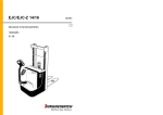
Drawing and Illustrations
Page 32 of 47
4-25-2011
Rev B
Page 33 of 47
4-25-2011
Rev B
3
4
2
Cust orurr Reo.r
VI~•
PE
PoputClt~d Cha.n :ls:
0
0
5.1
-
-
-
-
•
c
c
Page 34 of 47
4-25-2011
Rev B
0.0000
Bl
I
I
-
Q)
I®
0
0
0
0
c
fQ)
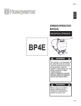
70MM HIGH SPEED FAN
@)
@
CHASSIS GROUND STUD
®
MS3102E22- 2P
(l)
I®
L5- 20R OUTLETS X 4
STAINLESS BACKPLATE
REMO TE TERMINAL BLOCK
MS3102E22- 2SW
@
20 AMP SP CIRCUIT BREAKER
®
USB MONITORING PORT
®
®
AI
4
SMART SLOT
EPO S\JITCH P.ACK
8
70MM FAN GUARD X 2
3
::.:;;;;::,';';"k ~
1
=~~~" ..
:rt~~'"""
2
Powersto.r Inc.
r-..,... ........ ,.. .... f"''. • •
,..,..,.,.,...
.....
1
~
A
0
.
,
..,_
"
:o
~
I
--
,.9.11-0()110
"
.II~ \
Ul"t&I!..~I·XA
BATTERY CABINET SPECIFICATIONS
I PS3JOORM
ForuseWith PS31S<n000
PS3-72V
8alletv Pack PIN PS3-48V
,_,.l ,.
..... I
I{
I
I
tlf r~ o <U)t
:-;:'Iii
~J \h~
·~...y l.l9 1
•
..Witte.~.U.
.._.,<rMIID:O.rD"aaii''IIIIIR
'fi4C
20 h
•
a.... r-
r
!1 .,t l 0 tl"f l " "
e---.11-,.f
a-lii"A.~r:
I
O"'~t
U.1779.~>1JLI.We<l l
ll!',j)I"'~ In PliTt ~nttwnnDll1
PS3·12VIlATI
pliO! wrtiGI\ opptO>r.ll
2UBa:leryPKk
P30300R"
.,. I ....... I
....." '
o) M
<HIUit
' (
_
..._,_
\
'""
1
Page 35 of 47
4-25-2011
Rev B
"""•
I
I :~
ll....t.N:)
P~nv.,
PEK
_.,...., _
ll't;C ..,..e ~lf:GII!
Gactarabtug. UO Xl871
~.1'\Cif ..0 . rei CIMottltc
~ ~ •'"' t i 1l r•
tM'AftOIIIC:Iftlrt..
WI> IO.OOO I
Pollo:Mtilr ..C
0013 Slledy Qo.'f Cl
lrl::wrt\3tbn Ill"'~ h: PfOP~it", t1
f ~'i AA
a!.Ql.(l4
1-.·-"
"'"
Page 36 of 47
4-25-2011
Rev B
Cable assembly layout
Note: All mil connectors to have strain relief
Part number M85049/52520W
Page 37 of 47
4-25-2011
Rev B
Rack Ear Set for UPS
Page 38 of 47
4-25-2011
Rev B
Test Reports
Dielectric Withstand Voltage Test Procedure
For LCS UPS
Page 39 of 47
4-25-2011
Rev B
Dielectric Withstand Voltage Test Procedure
For LCS Core Mission Equipment
LCS TBD_2
Prepared By:
General Dynamics
Advanced Information Systems
100 Plastics Avenue
Pittsfield Ma 01201
Page 40 of 47
4-25-2011
Rev B
Table of Contents
Section
Title
1.1 Item Identification and Marking..........................................................................................................43
1.2 Prepare Tester......................................................................................................................................43
1.3 Execute Test ........................................................................................................................................43
1.4 Record Results.....................................................................................................................................44
Page 41 of 47
4-25-2011
Rev B
Page
Introduction
This procedure describes the equipment and method for performing a Dielectric
Withstand Voltage Test.
Referenced Documents
The following documents of the latest issue, unless otherwise indicated, form a part of
this document to the extent specified herein:
Manual for Dielectric Withstand Voltage Tester
UL 1950 or UL 60950, UL Standard for Safety for Safety of Information Technology
Equipment
Test Equipment
The test shall be performed using the following equipment:
QuadTech Guardian 6100 or 6200 Product Safety Analyzer (or equivalent)
Safety
WARNING
Dangerous voltages may be present on the front and rear panel terminals on the tester and
on the test leads and the leads of the unit under test. Follow all warnings in the user’s
manual for the tester being used while operating and servicing the tester. Dangerous
levels of electrical energy may be stored in the capacitance of the unit being tested.
Always discharge any stored energy in accordance with the manual for the tester being
used. Always make sure the high voltage indicator is not on when connecting or
disconnecting the unit under test.
Environmental Conditions
Page 42 of 47
4-25-2011
Rev B
The test will be executed at normal ambient room conditions.
Page 43 of 47
4-25-2011
Rev B
Test Procedure
1.1
Item Identification and Marking
Verify and record the identification of the unit(s) being tested (e.g., part number / model
number, name, serial number) on the Dielectric Withstand Voltage Test Data Sheet.
Record the test equipment name, manufacturer, model number, serial number, calibration
date, and calibration due date in the space provided on the Dielectric Withstand Voltage
Test Data Sheet.
1.2
Prepare Tester
Using the tester manual set up the tester to perform the Electric Strength test as described
in section 5.3 of UL 1950.
1.3
Execute Test
Connect the unit to be tested to the tester in accordance with the tester manual and
perform the test(s) described in section 5.3, Electric Strength, of UL 1950. Hold the test
voltage for 60 seconds.
The unit passes the test if there is no indication of insulation breakdown during the test.
Insulation breakdown is considered to have occurred when the current which flows as a
result of the application of the test voltage rapidly increases in an uncontrolled manner
(i.e., the insulation does not restrict the flow of current). Corona discharge or a single
momentary flashover is not regarded as insulation breakdown.
Page 44 of 47
4-25-2011
Rev B
1.4
Record Results
Record the results on the Dielectric Withstand Voltage Test Data Sheet. When testing
has been completed, sign and date the test data sheet in the space provided.
Page 45 of 47
4-25-2011
Rev B
Dielectric Withstand Voltage Test Data Sheet
Test Location:
Project:
Test Date:
Test Equipment
Name
Manufacturer
Model
Serial Number
Cal. Date
Test Results
Test Unit Identification
From
To
Insulation
Test
AC /
Type
Voltage
DC
(O,B,S,R)*
Page 46 of 47
Signatures
Test Engineer:
Print
Sign
D
QA:
Print
Sign
D
* See UL 1950 for definitions
Page 47 of 47


![41063-230_2_4 [Converted].ai](http://vs1.manualzilla.com/store/data/006111840_1-fec7d9e1dd6c0ba197391e6de7df6272-150x150.png)