1
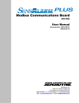
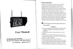
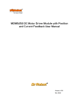
SEA-FIRE FIRE CONTROL SYSTEMS
FIRE CONTROL PANEL MANUAL
INSTALLATION MANUAL
®
ACCOMM
FIRE CONTROL PANEL TYPICAL
INSTALLATION
DETECTOR
HEAT
SMOKE
CONTROL
UNIT
DETECTOR
HEAT
SMOKE
POWER
12-24V
DETECTOR
HEAT
SMOKE
VENT
RELEASE
DISPLAY OUT2
ALARM
SOUNDER
NOT IN USE
NOT IN USE
HEAT
SMOKE
HEAT
SMOKE
GROUND
CYLINDER PRESSURE
SWITCH
24 VDC
GROUND DISCHARGE PRESSURE
SWITCH
24 VDC
®
FAULT
HEAT
SMOKE
ENGINE
DISPLAY OUT1
POWER
DETECTOR
DISCHARGE
LOW PRESSURE
ENGINE ROOM
131-520 - ADAPTER
ACCOMMODATION
SOUNDER
RESET
FIRESTOP
TECHNOLOGY
SILENCE
131-510 - DISPLAY PANEL
FEATURES
UP TO 4
DISPLAYS
RELAYS SHOWN IN NORMAL STATE
OUT4A
OUT4B
COM4
OUT3A
OUT3B
COM3
OUT2A
OUT2B
COM2
OUT1A
OUT1B
COM1
AUX
RESET
RELAY
OUT7A
OUT7B
COM7
OUT6A
OUT6B
COM6
OUT5A
OUT5B
COM5
131-500 - CONTROL UNIT
12/24 VOLT DC
EARLY DETECTION AND WARNING OF FIRE - 2 ZONE WITH ZONE INDENTIFICATION PANEL
FULL MACHINERY SHUTDOWN MANAGEMENT WITH 7 RELAYS PLUS 1 AUXILIARY RESET RELAY
COMPREHENSIVE FAULT MONITORING
CYLINDER PRESSURE AND DISCHARGE MONITORING OF EXTINGUISHER
STRATEGICALLY PLACED DISPLAY PANELS THROUGHOUT VESSEL
THE F IRE STOP F IRE C ONTROL P ANEL (FCP)
IS A LOW VOL TA GE FI R E DE TE C TI ON AN D
CONTROL SYSTEM DESIGNED FOR USE IN THE
MARINE AND OTHER TRANSPORT MARKETS.
T HE FCP
INTEGRATES FIRE EXTINGUISHER
MONITORING, FIRE DETECTION AND
MACHINERY SHUTDOWN CONTROL IN A
MODULAR DESIGN THAT CAN BE EXPANDED TO
MEET THE REQUIREMENTS OF A WIDE RANGE
OF APPLICATIONS.
11/09/08
VERSION 1.3
PAGE 1 OF 6
SEA-FIRE FIRE CONTROL SYSTEMS
FIRE CONTROL PANEL MANUAL
INSTALLATION
®
OPERATION
Normal monitoring mode
®
POWER
FAULT
During normal operation, the FireStop Fire Control Panel
(FCP) monitors detectors in 2 zones, monitors the Sea-Fire
extinguisher for pressure and discharge, and monitors for
faults.
DISCHARGE
LOW PRESSURE
ENGINE ROOM
92mm
45mm
Cut
Hole
ACCOMMODATION
RESET
During normal operation the green Power LED will remain lit.
FIRESTOP
TECHNOLOGY
SILENCE
Machinery shutdown
72mm
14mm
In the event of a discharge of the Sea-Fire extinguisher,
either automatic or manual release, the FireStop FCP will
initiate a shutdown of up to 7 machinery circuits. These will
typically include: engines, generators and ventilation.
Machinery shutdown will ensure that the extinguishing agent
in its proper concentration will remain in the enclosed
compartment and not be ingested or fuelled by the running
machinery.
Adapter card
The number of detectors on each zone can be increased via
use of the Adapter Panel.
131-510 - FRONT DISPLAY, SIDE,
REAR AND GASKET WITH CUT GUIDE
INSTALLATION
The adapter cards can support a mixture of smoke and heat
detectors.
HARDWARE
Silencing and Resetting Fire Alarm
Display Panel
Select an accessible locatio n a t the he lm s ta tio n f o r
installation of the Display Panel. Using the gasket template
supplied, drill the four fixing holes and the 45mm central
hole for the connection plugs.(See diagram above)
Fire detection
In the event of a detector activating, an alarm will sound
and a red LED will flash on the Display Panel and the ZIP
Panel. The alarm can be silenced by pressing the Silence
button on the Display Panel. The detectors can be reset by
pressing the reset button. A successful detector reset will
only happen if it is clear of heat, smoke. If the detector is
not clear, it will go into alarm again.
The FireStop Fire Control Panel has two detection zones.
System fault monitoring
1. Engine room - When heat is detected as present by
the engine room detector, the fire alarm will sound and the
red Engine Room LED will flash on the Display Panel. In
addition, the red Engine Room LED on the ZIP panel will
flash.
The display panel gives an audible and visual indication for
the following faults:
A reset button on the control panel enables the machinery to
be restarted.
During discharge of the cylinder, an alarm sounds and a LED
on the control panel will confirm low pressure/discharge.
Pressing the silence button will silence the alarm.
2. Accommodation - When smoke is detected by one of
the Accommodation detectors, the fire alarm will sound and
the Accommodation LED on the Display Panel will flash. In
addition the location of the detector in alarm will flash on the
ZIP panel.
It is recommended that the Display Panel is placed loosely
next to the Control Panel during the wiring installation. As
each component is fitted, the Display Panel will confirm that
the installation is correct by remaining fault free. After
successful installation, the Display Panel can be secured in
the correct location with the fastening kit supplied.
Control Panel
Cylinder pressure
Short circuits
Line faults
If a fault develops, the fault light will flash on the display
panel and an alarm will sound every 60 seconds. If the fault
is with the power, detector or pressure switch circuit then
the corresponding light will flash on the display panel as
well. If the fault is with an accommodation detector then the
location of the fault will be shown by a flashing LED on the
ZIP Panel. Check component wiring and press reset to clear
the fault.
The Control Panel should be installed in a convenient location
accessible to the ignition wiring and power.
Adapter Card
The Adapter Card should be installed in a convenient location
where the connections from the detectors can be made.
Zone Indentification Panel
Use template provided to mount in convenient location.
11/09/08
VERSION 1.3
PAGE 2 OF 6
SEA-FIRE FIRE CONTROL SYSTEMS
FIRE CONTROL PANEL MANUAL
INSTALLATION
®
ELECTRICAL CONNECTIONS - refer to schematic
As a minimum use No.16 AWG (SAEJ3788 & J1128) copper
wire conforming to the ABYC standards for marine use on all
wiring applications.
Input and Output terminals
Vent release. This output allows for an electromagnetic
r e le a s e to b e c o nne c te d to the c o n t r o l u n i t . D u r i n g
discharge, the output will deliver a current of 2 amps for 5
seconds. Observe correct polarity.
Warning sounder. If required fit Alarm sounder. Observe
correct polarity. Additional sounders can also be fitted at
each display panel. 24 volt.
Connect cylinder supervisory pressure switch. There is no
polarity for this connection. Remove EOL resister and fit at
cylinder pressure switch.
Connect cylinder discharge pressure switch. There is no
polarity for this connection. Remove EOL resister and fit at
cylinder pressure switch. Ensure that the Common and
Normally Closed contacts are used. The relays energise and
change state when the discharge pressure switch opens.
Detectors. Connect to Control Unit or Adapter Panel (See
diagram page 5). Observe correct polarity. Positive to
terminal 2 , negative to terminal 5 on detector base.
The detectors are grouped, with one adapter panel acting as
a hub for four detectors. A single Cat5 cable connects this
group of detectors to the ZIP Panel.
Remove 47k resistor from board terminal unless unused.
47k EOL resistor should be used on last engine room
detector.
Adapter Card. Connect ground to the power terminal. The
positive from the adapter should be wired through the
normally closed contacts of the auxiliary reset relay 24 Vdc.
Connect adapter to the control unit observing correct
polarity. Where multiple Adapter Panels are being used, they
should be wired in parallel via the single terminal output.
(See diagram page 4)
Ensure that 47K resisitors are in place on unused terminals.
The ZI P panel has four R J4 5 s o c k e ts o n the r e a r f o r
connecting to the Adapter Panels. These sockets are labelled
1 to 4. Connect the corresponding numbered Adapter Panel
via Cat 5 cable.
Machinery shutdown relays
Connect the Display Panel (131-510) to the Control Unit
(131-500) by using the CAT5 cable provided. Either RJ45
plug may be used. Connect the ZIP Panel (123-207) to the
Control Panel. Additional control panels can be connected to
the second RJ45 socket on the first Display Panel or ZIP
Panel.
Connect 24 volt to the power terminal. Observe correct
polarity. There are two power connectors allowing power to
be taken from two independent battery supplies. I t is
recommended that the Fire Control Panel is connected to a 3
amp breaker at the distribution panel.
Zone Identification Panel (ZIP)
ACCOMMODATION
ZONE
®
ENGINE
ZONE
CONTROL UNIT
VENT
RELEASE
DISPLAY OUT1
ALARM
SOUNDER
DISPLAY OUT2
NOT IN USE
NOT IN USE
GROUND
CYLINDER PRESSURE
SWITCH
24 VDC
GROUND DISCHARGE PRESSURE
SWITCH
24 VDC
RELAYS SHOWN IN NORMAL STATE
OUT4A
OUT4B
COM4
OUT3A
OUT3B
COM3
OUT2A
OUT2B
COM2
OUT1A
OUT1B
COM1
AUX
RESET
RELAY
OUT7A
OUT7B
COM7
OUT6A
OUT6B
COM6
OUT5A
OUT5B
COM5
There are seven relays for machinery shutdown rated at 16
amps. The relays are not energised in normal standby
mode. Do not exceed the relay rating.
Gasoline engines
Gasoline engines may be shutdown by interruption of the
primary ignition power from the key switch to the ignition
coil. Terminals A and COM would be used in this case.
Diesel engines
There are two common methods for shutting down diesel
engines.
1. Fuel solenoid valves that are energized to open on start
up, and de-energized to shutdown. Terminals A and COM
would be used in this case.
2. Fuel solenoid valves that are open when de-energized
and energized closed to shutdown. Terminals B and COM
would be used in this case.
When using method number 2, it is recommended by some
engine manufacturers to limit the shutdown activation
(energized) time applied to the fuel solenoid. In this type of
application please contact Sea-Fire.
Ventilation
I n m o s t c a s e s the v e ntila tio n w ill b e s to p p e d b y a n
interruption of power. Terminals A and COM would most
commonly be used.
131-500 - CONTROL UNIT
11/09/08
VERSION 1.3
PAGE 3 OF 6
SEA-FIRE FIRE CONTROL SYSTEMS
FIRE CONTROL PANEL MANUAL
TYPICAL SYSTEM WIRING
®
cat 5 cable
POWER
DISOHARGE
FAULT
LOW PRESSURE
ENGINE ROOM
FIRESTOP
ENGINE
ZONE
CONTROL UNIT
+
-
SOUNDER
ACCOMMODATION
RESET
VIP STRM
1
PILOT HOUSE
2
PORT GUEST
2
GALLEY
3
STBD. GUEST
3
SALON
4
MASTER ROOM
4
1
ACCOMMODATION ZONE
SEA-FIRE
VENT
RELEASE
DISPLAY OUT 1
ALARM
SOUNDER
SILENOE
+
+
+
+
NOT IN USE
DISPLAY OUT 2
NOT IN USE
GROUND
+24
VDC
-
cat 5 cable
CYLINDER PRESSURE
SWITCH
1
PELAYS SHOWN IN NORMAL STATE
OUT4A
DISOHARGE
FAULT
LOW PRESSURE
RESET
OUT7A
OUT3B-
-OUT7B
COM7
OUT2A
OUT6A
OUT2B-
-OUT6B
COM2
SILENOE
COM6
OUT1A
OUT5A
OUT1B-
-OUT5B
COM1
AFT CREW 1
2
RELAY
OUT3A
COM3
+
-
SOUNDER
ACCOMMODATION
FIRESTOP
RESET
COM4
ENGINE ROOM
DC 24V
5A
AUX
OUT4B-
POWER
A1
A3
A2
A4
DISCHARGE PRESSURE
SWITCH
GROUND
+24
VDC
1
2
AFT CREW 2
3
3
4
4
COM5
cat 5 cable
cat 5 cable
A
d
a
p
t
e
r
1
+ -
1
2
+ - + -
A
d
a
p
t
e
r
2
3
4
+ - + -
+ -
1
2
+ - + -
Ad
ap
te
r
3
3
4
+ - + -
1
2
+ - + -
+ -
3
4
+ - + 2
5
1
6
4
2
5
1
6
4
2
5
2
5
2
5
2
5
1
6
1
6
1
6
1
6
4
4
PORT GUEST
2
1
4
5
2
6
1
5
2
6
1
4
4
VIP
STBD.GUEST
4
CREW 2
MASTER
4
CREW 1
GALLEY
5
2
6
1
5
2
6
1
5
6
4
4
P/H
SALOON
11/09/08
VERSION 1.3
PAGE 4 OF 6
SEA-FIRE FIRE CONTROL SYSTEMS
FIRE CONTROL PANEL MANUAL
TYPICAL LAYOUT
FIRESTOP ZONE CONTROL PANEL
POWER
VIP STATEROOM
PILOT HOUSE
FAULT
PORT GUEST STATEROOM
GALLEY
DISCHARGE
STBD GUEST STATEROOM
SALOON
LOW PRESSURE
MASTER STATEROOM
ENGINE ALARM
AFT CREW 1
ACCOMM ALARM
AFT CREW 2
RESET
FIRESTOP
TECHNOLOGY
SILENCE
PRESS RESET TO RESTART
MACHINERY AFTER SHUTDOWN
PART NO. 123-207
11/09/08
VERSION 1.3
PAGE 5 OF 6
SEA-FIRE FIRE CONTROL SYSTEMS
FIRE CONTROL PANEL MANUAL
MOUNTING TEMPLATE
CUT OUT
11/09/08
VERSION 1.3
PAGE 6 OF 6