1
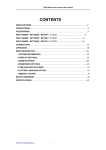
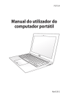
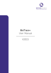
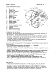
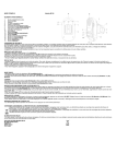
User Manual for the NeXus-10 Manufactured in Europe, Worldwide distributor: Mind Media B.V. Schepersweg 2B NL-6049CV ROERMOND-HERTEN WWW.MINDMEDIA.NL Email: [email protected] Tel: +31-0475-410123 Fax: +31-475-330602 Distributed in the USA by: Stens Corporation 3020 Kerner Blvd, Suite "D" San Rafael, CA 94901-5444 Phone: (800) 257-8367 (415) 455-0111 Fax: (415) 455-0333 Email: [email protected] Web: www.stens-biofeedback.com NeXus-10 manual 0088 Version 1.32 June 2005 Code 92-0298-001-0-1.32 0088 2 Version 1.32 NeXus-10 manual Contents 1 INTRODUCTION 4 PRODUCT DESCRIPTION INTENDED USE PRODUCT LIABILITY LIMITATION OF LIABILITY 4 5 6 6 2 ABOUT THIS MANUAL 7 PRECAUTIONARY MEASURES WARNINGS & CAUTIONS Warnings Caution 7 7 7 9 3 CONTENTS OF THE PACKAGING 10 4 IDENTIFICATION OF IMPORTANT PARTS. 11 5 INSTALLATION 12 6 OPERATING INSTRUCTIONS 15 7 TECHNICAL BACKGROUND 24 8 MAINTENANCE 40 9 TROUBLE SHOOTING 41 The light does not go on when switching on the NeXus-10 The light stays orange No Bluetooth connection possible Bad signal / no signal on channels with electrodes. Recording error on SD (Orange blink). 10 SPECIFICATIONS 0088 41 41 41 42 42 43 3 Version 1.32 NeXus-10 manual 1 Introduction Product description The NeXus-10 is a 10 channel physiological monitoring and biofeedback platform that utilizes Bluetooth 1.1 class 2 wireless communication and flash memory technologies. NeXus-10 offers data acquisition at up to 2048 samples per second. The advanced technology preamps enjoy independent 24 bit A-D converters per channel with DC coupled amplifiers allowing DC to 800 Hz (-4dB) recording including EEG, ECG, EMG, EOG, true DC and slow cortical potentials. Because this system uses carbon cables with active shielding, movement and noise levels are very low by design. Figure 1 NeXus-10 The first four channels operate at a sample frequency of 2048 Hz and can be used for EEG, EMG, ECG, EOG and SCP (Slow cortical potentials) measurements. The second four channels operate at a sample frequency of 128 Hz and can be used for RSP, BVP, SC/EDR, Skin-Potentials and SkinTemperature measurements. The remaining two channels are available for SpO2 oximetry and/or pulse or event synchronization. 0088 4 Version 1.32 NeXus-10 manual Intended use The NeXus-10 is a battery powered biofeedback device, intended to monitor and feed back physiological parameters on the human body for relaxation training, muscle reeducation and prescription use. Please note: the system is NOT intended for use in a life supporting system or for vital monitoring. For USA based customers/end-users: The NeXus-10 Biofeedback Units are available BY PRESCRIPTION ONLY! Please consult with your clinician to find out if they are appropriate for your individual situation. 0088 5 Version 1.32 NeXus-10 manual Product liability Limitation of liability Insofar as is maximally permitted under the applicable prescriptive law, neither Mind Media nor its suppliers or dealers are liable under any circumstances for any indirect, exceptional, incidental or consequential damages arising from the use of the product or from the inability to use it, including (but not restricted to) the damage arising from loss of goodwill, work interruption, computer defects or faults or any other damage or losses consequential upon business interruption, even if the possibility of these occurring had been mentioned and irrespective of the legal or impartial theory (agreement, unlawful act or otherwise) on which the losses are based. In any case and pursuant to any of the provisions of the present agreement, the total liability of Mind Media is limited in its entirety to the sum of the price that was paid for this product and the fee for the product support granted by Mind Media under a (possible) separate support contract, with the exception of death or personal injury arising from negligence by Mind Media insofar as the applicable prescriptive law forbids limitation of damages in such cases. Mind Media cannot be held liable for the consequences of any incorrect information furnished by its staff or for any errors in this user guide and/or other accompanying documentation (including trade documentation). The other party (the user of the product of his or her representative) must hold Mind Media harmless and indemnify it against any third party damages, irrespective of their nature and irrespective of the relationship with the other party. 0088 6 Version 1.32 NeXus-10 manual 2 About this manual This manual, which is intended for the user of the NeXus-10, contains general operating instructions, precautionary measures, maintenance instructions and information about components. To maximize the safety, service life and efficiency of the system, it is important that you read this manual through carefully and familiarize yourself with the various controls and accessories before starting to use the system. Precautionary measures This section contains general warnings and precautionary measures that are important for the safe use of the system. : manual contains important safety information : internally powered, type CF Warnings & cautions Warnings • Transport the NeXus-10 in its original case. • See manual of the PC software for details about the PC specifications. • Only use sensors and electrodes as described within this manual and specified by Mind Media. • Do not combine the use of the NeXus-10 with any other electronic device, except those specified in this manual. • Before batteries are replaced disconnect the patient from the NeXus-10. Make sure that the NeXus-10 is switched off, light is off. All batteries have to be replaced simultaneously, and all have to be of the same type. Note the orientation of the batteries. It is advised to place fresh batteries before each use to make sure the system operates long enough. • When using rechargeable batteries always charge according to instructions of the battery manufacturer. • This system is not suitable for use in an inflammable mixture of anesthetics and air, oxygen or nitrous oxide. • This system is not suitable for sterilization. • Do not use aggressive chemicals to clean the system • Do not expose the system to direct sunlight, heat from a source of thermal radiation, excessive amounts of dust, moisture, vibrations, or mechanical shocks. 0088 7 Version 1.32 NeXus-10 manual • • • • • • • • • • • • • • • The NeXus-10 is totally isolated from the mains (110/220V) due to battery operations, but make sure the PC is installed according to local regulations and safety precautions. Disposable electrodes which are used for EMG measurement etc may be a biohazard. Handle, and when applicable dispose of these materials in accordance with accepted medical practice and any applicable local, state and federal laws and regulations. Reusable electrodes present a potential risk of cross-infection especially when used on abraded skin, unless they are restricted to a single patient or sterilized between patients. When sterilizing electrodes, employ only gas sterilization. Store electrodes within separate bag within the packaging to prevent contamination Not to be immersed in any liquid If any liquids or moisture penetrate the system or any part thereof, remove the batteries from NeXus-10 and have the system checked by an approved technician. Take care in arranging patient and sensor cables to avoid risk of patient entanglement or strangulation When the distance between the Bluetooth PC receiver and the NeXus-10 is more then 10 meters or when there are conducting materials in the straight line between the Bluetooth PC receiver and the NeXus-10 signal quality cannot be guaranteed. Do not use an operating cellular phone within 30 cm of the NeXus-10 to avoid excessive noise on the signals Not to be connected to a patient undergoing MRI, Electro surgery or defibrillation. Not for critical patient monitoring. Not defibrillator proof. Sharp bends or winding the cables in a loop smaller than 5 cm may damage the cables Dispose of batteries according to local regulations The NeXus-10 contains recyclable materials that can be harmful for the environment. Specialized companies can separate these materials when the apparatus is disassembled. Before disposing of the apparatus, enquire about the local waste management regulations. 0088 8 Version 1.32 NeXus-10 manual Caution • • • • When the NeXus-10 is not in use for more than a week, the batteries have to be removed to prevent damage in case they start leaking. Except for the batteries there are no user serviceable parts within the NeXus-10. Repairs can only be performed by the manufacturer. The design of the NeXus-10 is such that no calibrations are needed. There are no known side effects from the use of this equipment. 0088 9 Version 1.32 NeXus-10 manual 3 Contents of the packaging Standard contents NeXus-10 package (NX10EH) 95-0928-0-0 NeXus-10 95-0007-001 Bluetooth USB module (MSI or LinkSys) 75-0924-001 Suitcase for the device and optional accessories 07-1000-100 Leather carrying case Optional accessories: NX-EXG2-Snap NX-REF1-Snap NX-EEG2 NX-REF1-EEG NX-SCP1A NX-REF1-SCP NX-TMP1A NX-AUX1A NX-GSR1A NX-BVP1A NX-RSP1A 95-200-15 NX-SPO2 0088 2 channel EEG/EMG/EKG/EOG sensor cable EEG/EMG/EKG/EOG ground reference cable 2 channel EEG sensor cable EEG ground reference cable 2 channel SCP sensor cable SCP ground reference cable Skin temperature sensor Skin Potential sensor SC/GSR sensor Blood Volume Pulse sensor. Respiration sensor Finger electrodes for SC/GSR sensor Nonin Oximetry (finger) Sensor 10 Version 1.32 NeXus-10 manual 4 Identification of important parts. 1 2 3 4 5 6 7 8 9 10 0088 On/Off Button Bluetooth USB interface Indication Light Patient ground connector Bipolar inputs A,B,C&D Auxiliary inputs E,F,G&H Battery compartment MultiMedia card slot. Nonin Oximetry and Trigger input Battery cover. 11 Version 1.32 NeXus-10 manual 5 Installation Install the Bluetooth interface according to the PC software manual. Install the PC software according to the PC software manual. Remove the battery cover from the NeXus-10 by pressing the marked area on the bottom of the cover while sliding the cover backwards. Figure 2 Opening battery cover NeXus-10 Place the two batteries according to the details shown inside the battery area and close the cover again. Make sure that no patient is attached to the NeXus-10 when replacing batteries. 0088 12 Version 1.32 NeXus-10 manual Figure 3 Battery placement NeXus-10 The NeXus-10 will not operate when the battery cover is not closed. Press the button on top of the NeXus-10 and check the light in the front. When the light shows orange followed by a green light, the NeXus-10 is operational. Figure 4 Front of switched on NeXus-10 When the light does not turn on, check the batteries and the battery cover. When the light stays orange the NeXus-10 is not functioning correctly. See chapter 10 for details on what to do next. 0088 13 Version 1.32 NeXus-10 manual Follow the directions in the software manual to install the BlueTooth drivers. These are supplied with the PC software. After installation of the BlueTooth environment, search for new BlueTooth devices and “add” the device to the list. When connecting the NeXus-10 to the PC for the first time, you will be asked for a passkey (sometimes also called a ‘pincode’). This passkey consists of the last 4 digits of the serial number of your NeXus10. This serial number will be listed by Windows and can also be found at the bottom of the NeXus-10 encoder. Figure 5 Serial Number of NeXus-10 In the picture shown above the serial number is 0928050124. Thus the BlueTooth passkey would be ‘0124’. In your case the passkey will be different, but will still consist of the last 4 digits. After installation of the NeXus-10 device, Windows will designate 2 serial COM ports for the digital communication to your personal computer. The Passkey normally has to be entered only once, unless you connect your NeXus-10 or USB dongle to another computer. In that case you need to re-connect and thus re-enter the passkey. After entering the passkey you are ready to use your PC Software with NeXus-10. Please refer to the PC software manual for instruction on connecting and reconnecting the NeXus-10 to the Windows™ BlueTooth environment. 0088 14 Version 1.32 NeXus-10 manual 6 Operating instructions Switching the NeXus-10 on The NeXus-10 can be switched on by briefly pressing the button on top of the NeXus-10. When the light goes from orange to green the NeXus-10 is ready for operation. Switching the NeXus-10 off The NeXus-10 can be switched off by briefly pressing the button on top of the NeXus-10. This will result in the light going off. In some situations the NeXus10 will not switch off by pressing the button: 1) When a PC connection is active, or when an ambulatory recording is active; the latter is indicated by a blinking green light. You will first have to stop the session on the PC or stop the ambulatory recording. The ambulatory session can be stopped by pressing down the button for 4 seconds or longer. 2) When the battery cover is removed the NeXus-10 will always switch off, regardless of its status. Note that this can result in undesired effects so always switch the NeXus-10 off before removing the battery cover. Attaching connectors The connectors are protected against wrong entry, so make sure the red dot on top of the connector is positioned directly across from the red dot on the connector in the NeXus-10. Do not apply too much force; the need for force indicates wrong alignment, so check this first. Using Patient electrode leads Always use one unipolar shielded cable (snap connector or fixed Ag/AgCl electrode cup) for patient ground (Gnd. connection). Connect the electrodes for physiological measurements to input A,B,C or D. For a good recording, make sure the electrodes make good contact with the patient. The patient ground electrode is especially important in this case. Using other sensors Connect the sensor to one of the auxiliary inputs (E,F,G or H). 0088 15 Version 1.32 NeXus-10 manual Using the pulse oximeter (optional) Apply the sensor to the patient as indicated by the Nonin instruction manual. Connect the sensor to the XPOD module. Connect the XPOD module to the Nonin / trigger connection. The red light in the sensor should be visible. Using the On/Off button as a Marker button The button can be pressed during connection with the PC software and ambulatory measurements, to record special moments or situations. Note that pressing the button for more than 4 seconds will start/stop the ambulatory recording. Recording signals There are 2 main ways to use the NeXus-10: stationary and ambulatory. Stationary use In stationary use the signals that are measured by the NeXus-10 are sent to the PC (by Bluetooth) and processed and/or recorded by the PC software. Ambulatory use In ambulatory use the signals that are measured by the NeXus-10 are sent to a prepared flash card (Secure Digital format) that is placed inside the NeXus10. First, the PC software is required to initialize the flash card (see the PC software manual for more details) Then, place the initialized flash card into the NeXus-10. Switch off the NeXus-10 and open the battery cover. Then place the flash card with the label of the card towards the top of the NeXus10 and press to enable the reader lock. To remove the flash card press again to release the card. Then, connect all desired sensors and start up the NeXus-10, as described above. Then, press the ON/OFF button for more than 4 seconds. The green light will start blinking, indicating that recording on the flash card is busy, or, if an error situation is present, the light will blink orange to indicate this. The recording can be stopped by pressing the ON/OFF button again for more than 4 seconds. After shutting down the NeXus-10, the flash card with the recorded signals can be read by a flash card reader on the PC for further processing. 0088 16 Version 1.32 NeXus-10 manual 7 NeXus-10 Sensors The electrophysiological Sensors: Inputs A,B,C and D acquire electrophysiological signals through the advanced DC instrumentation amplifiers that are built into the NeXus-10. Because of this design, expensive active amplifiers are no longer required for each electrophysiological modality. The DC instrumentation amplifiers amplify the difference between a ‘plus’ and ‘minus’ signal. The patient ground (reference) electrode is required to keep patient potential and NeXus-10 potential at about the same level. When using the inputs A-D the ground (reference) electrode must always be used. Its location on the body is not critical and depends on the application. For EEG the ground reference is often put on the ear or elsewhere on the head. Since the input impedance of the active channels is very high (1012 Ω), the influence of electrode impedance is very small. It should not be necessary to perform electrode impedance measurements. Instead the NeXus-10 offers electrode OFFSET checking, even while recording data. A poor electrode contact results in a high electrode offset. If the offset becomes too high, NeXus-10 will ‘flatline’ the signal. The PC software may warn you during a live recording when the offset of an input is too high. All electrode cables are shielded with the average of the ‘plus’ and ‘minus’ electrode signal (active shielding). This ensures a measurement that is virtually free of movement artifact. Mains (110/220V) interference (50/60Hz) is hereby also reduced to a minimum. After the first amplifier stage the signals go directly to the ADC. No high pass or low pass filters that can cause signal phase shifts or filter overflows are present. All further digital processing takes place on your PC or notebook computer. 0088 17 Version 1.32 NeXus-10 manual The dual channel EXG Snapon Cable (NX-EXG2-Snap) This cable provides 4 standard snap-on connectors for two bi-polar inputs. It can be used for electrophysiological signals between DC and 800 Hz such as EEG, surface EMG, ECG and EOG. Figure 6: NX-EXG2-Snap cable Please note: we do not advise that this cable be used for SCP signals.For slow cortical potentials the NX-SCP1A cable should be used. For each input channel there is a RED (positive) and BLACK (negative) snapon. When the cable is used for input A&B, the red and black connectors marked with ‘1’ will record data for input A. The ones marked with ‘2’ will record data for input B. If sensor inputs C&D are used, connectors marked ‘1’ will record on ‘C’ and ‘2’ will record on ‘D’. 0088 18 Version 1.32 NeXus-10 manual Because a bi-polar input always requires a ground electrode, you will need the snap-on ground reference electrode shown below. Figure 7: NX-EXG-Ref1-Snap cable This cable has a snap-on electrode on one end, and a micro-coax connector on the other end. Please connect the micro-coax connector to the input marked ‘Gnd.” On the NeXus-10. In the pictures on the next pages samples of EEG, ECG and EMG signals are shown, all recorded with this cable. But different types of electrodes and different locations on the body are used. 0088 19 Version 1.32 NeXus-10 manual A sample EEG signal: In the picture below a sample EEG signal is shown, containing a mixture of Alpha waves and low amplitude Beta waves. Raw EEG signals in the range of 1-45Hz typically show amplitudes between 10 and 50 microvolts (pk-pk) In this case the EEG signal was recorded on Input A, with the groundreference electrode on the right mastoid (A2), the positive electrode (red, marked with 1) on the Cz location and the negative (black, marked with 1) on the left mastoid. (A1) The picture of the 10-20 system below shows these locations. Figure 8: the 10-20 Electrode System 0088 20 Version 1.32 NeXus-10 manual For 1 or 2 channel Neurofeedback, C3 and C4 are also often used. With NeXus-10 you can record up to 4 channels of EEG. Recording EEG signals with the NX-EXG2-Snap cable NeXus-10 requires snap-on EEG electrodes. In this case the 2RT3 ** electrodes were used. Before applying these electrodes, the skin should be prepared with skin-prep and electrode paste. ** Please refer to professional publications and literature on EEG and neurofeedback for more information on the 10-20 system, skin preparation and electrode locations. ** Please contact your NeXus-10 reseller for information on these or compatible electrodes, skin preparation and electrode paste products. 0088 21 Version 1.32 NeXus-10 manual A sample surface EMG signal: With the same NX1-EXG2-Snap cable you can record surface EMG signals. In that case you will also need to place a positive, negative and ground electrode on the body. A sample of a single channel EMG signal is shown below during relaxation and during contraction. The range shown is 500 microvolt pk-pk. A digital EMG bandpass filter was set to 20-500Hz in the PC software. This signal was measured on the masseter (jaw muscle) using a triple pregelled electrode. This electrode offers standard 20 mm distances between the electrode and is pre-gelled, so it has improved skin contact. For wide EMG placements, single surface electrodes may also be used. 0088 22 Version 1.32 NeXus-10 manual Figure 9: Triple Gel electrode on Masseter Figure 10: Wide placement on Upper Trapezius For wide placements of EMG electrodes, single electrodes should be used. Please contact your reseller for more information on these or compatible EMG electrodes. We advise you to use pre-gelled electrodes. 0088 23 Version 1.32 NeXus-10 manual A sample ECG/EKG signal: The NX1-EXG2-Snap cable also enables heart rate detection through ECG signals. A sample signal of an ECG signal on input B is shown below. Notice that the R peak (of the QRS complex) should be pointing upwards for the HR detection (in the PC software) to work correctly. In this case the signal is displayed in a range of 3000 microvolts peak to peak and has a DC offset of 12000 microvolts. This signal was obtained from a vertical electrode position as shown below. (also called “Lead II”) Figure 11: ECG Lead II Chest Placement 0088 24 Version 1.32 NeXus-10 manual When a chest placement is not possible or not desirable, the positive (Red) electrode and ground electrode can also be placed on the left wrist and the negative (Black) electrode on the right wrist. This placement will pick up EMG artifact. A sample of such an ECG with wrist placement is shown below. Notice that the range of the ECG signal now is smaller (in this case 400 microvolts peak to peak) and that the signal looks much noisier. The noise in this example is EMG activity that is picked up by the same electrodes. When the EMG noise becomes too strong, the R-peak may no longer be visible and the heart rate (HR) may in such a case not be computed correctly by the PC software. To reduce EMG artifact, the subject should relax arm and chest muscles. Figure 12: ECG wrist placement (front view) A sample EOG (DC) signal: 0088 25 Version 1.32 NeXus-10 manual The same NX1-EXG2-Snap cable may be used to measure the EOG (electro-oculogram) which is a DC signal that shows the electrical activity when the eyeball moves. The EOG can be measured in a horizontal fashion (for detection of eyeball movements from left to right). In the sample below the EOG was measured vertically. (Eyeball movement Up and Down) Notice the negative DC offset: about 8000 microvolts. This short 2 second trace shows the eyeball in neutral position, then looking up and then looking down and going back to neutral. Standard single pre-gelled electrodes were used. Figure 13: Vertical EOG placement 0088 26 Version 1.32 NeXus-10 manual NX-SCP1A: sample SCP (DC) signal: The NeXus-10 can record EEG and SCP signals simultaneously, or in other words it can record signals between DC (0Hz) and 40-100 Hz for EEG. The SCP signal is usually averaged over a certain window so only the slow DC changes will visible. Below a sample of an SCP signal is shown. Notice how this SCP signal has a DC offset of about 11400 microvolts (pk-pk) and notice that negative values are plotted upwards. This is a polarity convention in neurophysiology. In this sample the trend of the SCP is in the positive direction (the signal moves downwards = positivity). Figure 14: NX-SCP1A cable 0088 27 Version 1.32 NeXus-10 manual For SCPs, the NX-SCP1A cable is used with the RED electrode on the Cz, the Black-1 electrode on the left mastoid and the Black-2 electrode on the right mastoid. This cable is essentially a dual channel cable and can be used for obtaining 2 channel EEG data from the same electrodes (left mastoid-Cz and right mastoid-Cz) as well. The positive (Red) Cz electrode combines the positive electrodes of channel 1&2. This SCP cable uses high quality sintered electrodes. Figure 15: SCP electrode placement For ground reference, we advise that the NX-Ref1-SCP cable be used. This is also a sintered electrode and may be placed anywhere on the face or in the neck/shoulder area. Sintered electrodes provide a greater DC stability and therefore are more suitable for SCP recordings. Before each use, please prepare the skin carefully with alcohol, skinprep (NuPrep) and EEG-paste (10-20). It usually takes some time before the electrodes are ‘stabilized’, so we advise you to wait 5-10 minutes before you start the actual SCP recording. After use, gently clean the electrodes with warm water and tippex, to remove the EEG-Paste from the electrode cups. This cable can be used to measure SCP and the EEG simultaneously. 0088 28 Version 1.32 NeXus-10 manual The dual channel EEG Cable (NX-EEG2) This bi-polar cable uses standard 10 mm EEG cup electrodes with silver-silverchloride coating. It has two negative cups (labeled black) and two positive cups (labeled red). The cups labeled with the number 1 are used for channel A or channel C (red1, black1). The cups labeled with the number 2 are used for channel B or channel D. (red2, black2) Figure 16: EEG electrode cable. Please note that this cable is bi-polar, and it can be used for 1 channel of EEG or for 2 channels of EEG. In both cases a ground reference cable must be placed on the body. The ground cable may in this case also be the snap-on cable (Type NX-EXG-Ref1-Snap) An example of a single bi-polar channel use would be to place the ground reference cable on one of the mastoids, the positive cup (red 1) on the C3 and the negative cup (black 1) on C4. The other two electrodes (red2, black2) would not be used. See fig. 17 on the next page. An example of a dual channel bi-polar montage would be C3-F3 (channel 1) and C4-F4 (channel 2). See fig. 18 on the next page. Please note that the in the EEG literature many different electrode placements are published, most of which are supported by this cable. 0088 29 Version 1.32 NeXus-10 manual Figure 17: single channel, bi-polar placement example. Figure 18: dual channel, bi-polar placement example. 0088 30 Version 1.32 NeXus-10 manual The SC/GSR Sensor (NX-GSR1A) The NeXus-10 skin conductance sensor (or GSR for galvanic skin response) measures the sweat gland activity, which is a sensitive indicator of arousal. Skin conductance is expressed in micro-mho or micro-siemens and increases when the arousal level increases. During relaxation, the SC level normally decreases. Because of the NeXus-10 ultra high 24 bit resolution, changes of up to 0.001 micro-mho can be detected in the range from 0.1 to 1000 micro-mho. Figure 19: Skin Conductance Sensor This sensor requires Ag-AgCl finger electrodes that snap into the two connectors. Polarity of the electrodes is not important. The sensor is designed to measure minute relative changes in skin conductance. A sample of the placement of the finger electrodes is shown on the next page. 0088 31 Version 1.32 NeXus-10 manual The signal below shows a sample skin conductance signal during relaxation. At 00’07” there is a temporary increase of the SC signal; the general trend, however, is downwards. Figure 20: Example of SC signal 0088 32 Version 1.32 NeXus-10 manual The Skin Temperature Sensor (NX-TMP1A) The NeXus-10 temperature sensor supports very high resolution temperature reading from the skin. It measures relative changes of up to 1/1000th degree Fahrenheit or Celsius in the range from 10-40°C. (50-104°F) Skin temperature is often measured on the fingertips and changes rather slowly. The sensor can best be placed on the finger using medical self adhesive tape. In the sample below, the temperature changes less than 0.01 degrees Fahrenheit over 15 seconds. Figure 21: Example of a temperature signal (Fahrenheit) 0088 33 Version 1.32 NeXus-10 manual The Blood Volume Pulse Sensor (NX-BVP1A) The NeXus-10 BVP finger sensor measures relative blood flow, using optical electronics that measure near-infrared light. During each heart beat, blood flows through the arteries and blood vessels. At the peak of blood flow, the BVP signal peaks as well. The height of the peaks indicate the relative bloodflow which correlates with the level of vasodilation/vasoconstriction at that point. The distance between the peaks can be used to obtain the absolute heart rate (HR) or interbeat interval. (IBI) The BVP signal is usually sampled at frequencies of up to 128 SPS. If greater precision in HR or IBI is required, for instance for research purposes, we advise using an HR computed from an ECG signal, which can be sampled at up to 2048 SPS. (samples per second) For clinical applications, the BVP sensor usually is sufficient and usually more comfortable, since it can be worn on the fingers. Note, however, that the BVP sensor is sensitive to movement artifact. Movement and gravity may impact the BVP signal. Therefore we advise that during a session the subject sit comfortably and still. On the next page two examples of BVP signals are shown. 0088 34 Version 1.32 NeXus-10 manual Below a typical BVP signal is shown with no artifacts and a strong pulse. The pulse amplitude shown below is about 200 millivolts (mV) Figure 22: Example of a clean BVP signal. The next picture shows a rather weak signal (10 mV amplitude) containing movement artifact from 00’29” to 00’31”. During such artifacts, the heart rate (HR) usually cannot be computed correctly. Preferably a BVP sensor should output at least 10 mV, in order for the signal to clear enough to measure HR and vasoconstriction levels. Figure 23: Example of BVP signal with artifact 0088 35 Version 1.32 NeXus-10 manual The Respiration Sensor (NX-RSP1A) The NeXus-10 respiration sensor measures the relative expansion of the abdomen or thorax during inhalation and exhalation. It consists of an elastic belt that is worn around the body and a sensor part shown below. The elastic belt comes in two sizes, small and large. The sensor can be worn on top of a shirt or sweater. For best results, we advise that there be only 1 or 2 layers of clothing between the sensor and the skin. When recording the respiration activity, the elastic belt always remain under some tension, such that even during full exhalation the belt still won’t be loose. Since it measures relative movement, the sensor does not need to be calibrated. 0088 36 Version 1.32 NeXus-10 manual In the picture below the positioning of the respiration sensor is shown on the thorax and on the abdomen. When used on the abdomen, the sensor part normally is placed around the position of the navel. Figure 24: Example of an abdominal respiration curve 0088 37 Version 1.32 NeXus-10 manual 8 Technical background In the NeXus-10 the following items can be found: connectors + analog inputs (A-D) for electrophysiological signals connectors + analog inputs (E-H) for auxiliary signals Real Time Clock (RTC) Battery compartment Bluetooth serial connection Auxiliary input stage Each auxiliary input has a 5-pin connector. Signals on this connector are +5V output, -5V output, GND, +signal input and -signal input. The +5V/-5V/GND pins are used to power an active sensor. The + and - inputs are connected to an instrumentation amplifier with a gain of 1. An unconnected input will automatically be switched off (i.e. will show a zero signal without noise). The output of the amplifier goes to the ADCs without any filtering. Real Time Clock (RTC) The RTC continuously keeps time, even if no batteries or external power are connected. The RTC uses its own button cell battery for power backup. Lifetime of this button cell is at least 5 years. Batteries Batteries are used as the power source for the NeXus-10. The NeXus-10 can work with both rechargeable and disposable batteries. Maximum operating time depends strongly on the type of battery chosen. Rechargeable batteries have both lower voltage as well as lower capacity (mAh). Therefore the measurement time is lower than when Alkaline batteries are used. The power consumption increases when more auxiliary sensors are added. The measuring time will then decrease. When good alkaline batteries (for instance Duracell MN1500) are used, on average the duration of battery power, should be at least 10 hours, when only the EXG sensors (inputs A-D) are used. 0088 38 Version 1.32 NeXus-10 manual When batteries are changed, make sure that all batteries are replaced at the same time. Battery check: the NeXus-10 monitors the voltage of the batteries. Two thresholds are present. The first (ca 2.1 V) is the ‘battery low’ threshold. If the total battery voltage comes under this level the orange light will start to blink. At this point you may still have more than 30 minutes of battery life left, but we advise you to stop the recording and replace the batteries. If the batteries are not replaced the battery voltage will eventually drop below the ‘battery empty’ level (ca 1.9 V). Up to this point operation of the NeXus10 is still normal. When the ‘bat empty’ level is passed, the NeXus-10 will close the measurement file and shut itself down in an orderly fashion. TIP: in case you decide to use rechargeable batteries do NOT use NiCad batteries, their capacity is too low. Rather, we advise you to use NiMH batteries with a capacity of at least 2200 mAh. (milli-ampère-hours) The capacity of the rechargeable batteries is usually indicated on the battery itself. 0088 39 Version 1.32 NeXus-10 manual 9 Maintenance There are no user serviceable parts within the NeXus-10. Maintenance is limited to regular cleaning. Cleaning of the NeXus-10 can be done with a slightly damp soft cloth. Before cleaning, make sure the NeXus-10 is turned off and not in contact with a patient. 0088 40 Version 1.32 NeXus-10 manual 10 Trouble shooting The light does not go on when switching on the NeXus-10 The most likely reason is that there is no power available from the batteries. Make sure the batteries are charged and that the battery cover is undamaged and closed correctly. The light stays orange This indicates that the NeXus-10 is unable to start up correctly. First check the batteries. If the problem still occurs send the NeXus-10 back for repair. No Bluetooth connection possible Make sure the distance between the NeXus-10 and the Bluetooth interface is less then 10 meters. When possible check the working of the Bluetooth interface with another Bluetooth device. If it still does not work contact your supplier. Sometimes it is necessary to remove and then (again) add the NeXus-10 device to your BlueTooth Windows environment, so that it will be found again. In that case you would use the ‘Remove’ and ‘Add’ buttons as shown in the picture below: (actual screen display may vary) Under COM ports, settings should preferably be between COM3-COM9. 0088 41 Version 1.32 NeXus-10 manual Bad signal / no signal on channels with electrodes. Replace the electrodes on the skin of the patient. If this does not work, move the cable and check if this results in occasional signals on the PC. If this happens, the cable is broken and has to be replaced. If it is still not working, replace the cable with another cable and recheck. If it is working, use the new cable and dispose of the old cable. If it still does not work, check the working of the NeXus-10 with any available sensor or electrode. If the NeXus-10 is not working, send it for repair. Otherwise, replace non-working cables. Recording error on Flash Memory (Light blinks orange) Possible courses for this are: • No valid Flash card (Secure digital SD) • The Flash card was not formatted correctly • The Flash card is missing the Flash initialization files. • The Flash card is full. 0088 42 Version 1.32 NeXus-10 manual 11 Specifications NeXus-10: 0088 Classification of medical device : This apparatus meets all the requirements of the Medical Device Directive (93/42/EEC). : For Europe: IIa (rule 10) : For the USA: Class II medical device (510K exempt) : FDA Sec. 882.5050 Biofeedback Device. Safety conforms to * IEC 60601-1:1988 + A1:1991 + A2:1995 : Medical electrical equipment Part 1: General requirements for safety * EC 60601-1-2:2001 : Medical electrical equipment - Part 1-2: Electromagnetic compatibility Safety class according to IEC 60601-1 : internally powered, type CF Dimensions Weight Internal power supply Batteries Battery low indication level Battery empty shut down level Duration: (on average) : 11.4 x 9.8 x 3.7 cm (l x b x d) : 234 gram 2 x AA type rechargeable NiCad or NiMH 1.2V or disposable alkaline 1.5V 2.1 V ± 0.1V 1.9 V ± 0.1V 10-20 hours depending on sensor configuration. Bipolar inputs (EEG, ECG, EOG, EMG etc.) Typical noise level: <= 0.8 µV rms (@ 256 SPS, EEG Range 1-45Hz) Gain 19.5 x Input signal difference < 0.1 V Input common mode range -2V - +2V Input impedance > 1012 Ω CMRR 100 dB Connector LEMO 6 pin Accuracy ± 2% 0088 43 Version 1.32 NeXus-10 manual AUX inputs Gain Input signal range (diff.) Input common mode range Input impedance CMRR Output voltage Connector Accuracy Sampling: Resolution 1x -2V - +2V -2V - +2V > 1010 Ω 80 dB +5V, -5V, max. 5mA per channel LEMO 5 pin ± 2% 24 bits, Bipolar 12.2 nV per bit, AUX 0.238 µV per bit Sample frequency (Fs) Bipolar 2048 Hz, Aux 128 Hz Bluetooth communication: Bluetooth 1.1 class 2 Used profile Serial port profile Line of sight range 10 meter 0088 44 Version 1.32 NeXus-10 manual NeXus-10 is exclusively manufactured for Mind Media by: TMS International BV Office address: H. ter Kuilestraat. 181 7547 SK Enschede The Netherlands Mail address: P.O. Box 1123 7500 BC Enschede The Netherlands Environmental conditions for transport and storage -10ºC - +70ºC 10% - 90% 500 hPa - 1060 hPa Environmental conditions for normal use +10ºC - +40ºC 10% - 90% 500 hPa - 1060 hPa Please note: the manufacturer reserves the right to make technical changes without prior notice. 0088 45 Version 1.32