1
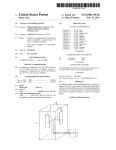
Data Sheet
Pim 21
Portable Passive
Intermodulation
Test Set
Taking performance to a new peak
Pim 21 - Portable Passive Intermodulation Test Set
The Pim 21 is a microprocessor controlled, portable test set
allowing detection of distortion components and assemblies
in radio base station, in-building-DAS installations and other
systems transmitting radio frequencies.
Non-linearity in radio frequency assemblies causes Intermodulation Distortion (IM). The purpose of the Pim 21 test set is
to specifically test for this distortion in passive signal paths,
known as Passive Intermodulation Distortion or pim. Components in coaxial feeder assemblies such as connectors, jumper
cables, splitters, hybrids, filters, DC blocks and antennas can
cause pim problems if they are not manufactured or assembled
properly.
Depending on the application pim can be measured in differ-
Benefits of Pim testing in the field
ent ways. In manufacturing and in lab environments, analyz-
• Detects nonlinear passive system components quickly, thus
ers which perform narrow frequency band sweeps are often
used. These systems are costly, heavy and very bulky. Pim test
systems for field technicians and engineers have to be accurate,
but also cost efficient, portable and battery operated. By using
two defined test frequencies, Pim 21 provides an excellent field
reducing network maintenance costs
• Increased network quality
• Increased channel efficiency resulting in optimized investment
effectiveness
proven combination of performance, price and portability.
Applications with Pim 21
The Pim 21 is designed specifically to aid communications technicians in the field locate components and assemblies which are
creating Pim and degrading the performance of the installation.
• Identify outdoor base station antennas and feeds or
in-building-DAS with poor or marginal Pim
• Identify broadband interference that affects antenna performance
Features
• Antenna test (without overloading, using adjustable power
level control)
• Adjustable level of customer specific test frequencies to
match power to application
• Pim Sensitivity of -153 dBc @ 850 MHz (typ -155 dBc)
• Self calibrating
• Rugged, weather-proof case (IP55 – closed lid)
• Very simple to operate
• Small, very portable
• Battery operated
• Communications port allows for documenting and storage of
test results on an external PC
• Helps technicians to locate discontinuities in
coaxial assemblies
• Optimize position of indoor antennas to avoid interference
caused by RF effects of ceiling grids, rusty rebar in concrete
and even rusty bolts in building structure
Field Proven Features of Pim 21
What Causes Pim?
The Pim 21 test system is a field unit designed for portability.
Passive intermodulation can be caused by a variety of fac-
This instrument allows field personnel to pinpoint the cause of
tors. Pim distortion is often the result of flaws in component
pim distortion quickly and easily.
design and manufacturing processes. Pim distortion may also
be caused by wear and tear on components due to mechanical
constraints or environmental conditions.
Manufacturing & Design
• Use of ferromagnetic materials, such as nickel or steel, within
the current path. Especially at higher power levels, pim can be
generated due to hysteresis effect of these materials and the
non-linear voltage to current ratio.
Read Pim and ambient RF Noise in 3 ways.
• Numerically on the lcd in -dBc
• Lcd Bar graph
• Quick view LED bar graph which indicates:
Green for Pim < -140 dBc, and
Red for Pim > -140 dBc
• Contaminations, like particles from machining operations or
soldering splatters that touch current carrying surfaces.
• Separation of current carrying contact zones through irregular
contact surfaces, corrosion and insufficient contact pressure.
• Dissimilar metals at contact areas.
• Insufficient thickness of plated metal causing RF heating
through the skin effect of RF.
• Bad solder joints.
Alarms
A pim Threshold Alarm is triggered whenever the pim level
Mechanical
exceeds -140 dBc (default). “Pim Alarm” led and switching
• Poor mechanical alignment of components
contact.
• Too much or too little torque at connections
• Contaminated connectors
Audio Frequency Indicator
The frequency varies in pitch depending on the measured
Environment
pim level. Rising pitch indicates higher Pim. The volume of the
• Daily temperature variations, thermal loading by the sun and
frequency is adjustable. Pim 21 allows the audio signal to be
RF heating vary junctions and can cause, often intermittent,
connected to external devices, such as walkie talkies.
Pim distortions.
• Wind-induced vibrations vary junctions, and can weaken or
break down joints.
What is Pim?
• Airborne dirt and moisture cause oxidation of materials and
cause pim distortion.
Pim distortion is caused by non-linear mixing of two or more
frequencies in passive devices like cables and connectors. Ideal
passive devices are considered linear. Pim signals are unwanted
because they interfere with signals in the receive path. In reality any linear component has a non-linear factor that can cause
pim distortion. For optimal operation of RF systems, pim has to
be kept at a very low level that has virtually no influence on the
network operation.
Antenna showing oxidation within the power divider. Tests with vector analyzer line sweep test did not reveal the problem. Pim 21 test
system could however clearly detect the issue and pinpoint the faulty
component.
How to test Pim
Specifications
Pim testing for field applications requires the injection of two
Pim Test:
CW signals (f1 and f2) into a system under test. Intermodulation products (IM) of the 3rd, 5th, 7th… order, caused by faulty
Single port reflection
measurement
Test Frequencies
2 custom frequencies*
components, appear immediately. The strongest intermodulation product is that of the 3rd order (IM3), which is measured.
Carrier Power Frequencies for these intermodulation products are calculated
Cellular
+20 to +33 dBm, in 1dB steps
as follows:
PCS
+33 dBm
Power Accuracy
±1 dB / carrier
fIM31
= (2 x f1) – f2
Pim Measurements
fIM32
= (2 x f2) – f1
Range
-80 to -153 dBc @ 850 MHz
(typical -155 dBc)
The picture below shows an example of passive intermodula-
Accuracy
tion. Frequencies f1 (869 MHz) and f2 (894 MHz) are located
±2 dB to -153 dBc @ 850 MHz
±3 dB to -155 dBc @ 850 MHz
in the Tx range, causing intermodulation fIM31 (844 MHz) and
fIM32 (919 MHz). Both IM products can cause serious interfer-
VSWR 2 frequency test
0 ~ 15 dB (Return Loss), ±3 dB
ence.
Display
LCD screen and LED bar
RF Calibration
Automatic with RF Power On
Internal Checks
All rails checked on power up.
Level Alarms
Selectable VSWR and Pim in both
audible and external jack
External Power
DC 10~16 V @ 3.5 Amps max
Battery Power
Cellular, typically 30 minutes
PCS, 20 minutes
Example of intermodulation caused by two CW signals. Since the chan-
Weight
17.6 lbs, 8 kg., nominal
Dimensions
13.5 x 12.9 x 6.0 inches
nel bandwidth of RF transmitters occupies usually a frequency range,
343 x 327 x 152 mm
resulting IM appears in a range of frequencies.
Enclosure
Ideally, f1 and f2 should be at the edge of the transmit guard
Operating Temp
Waterproof, IP55 stored, lid
closed IP40 operating, lid open
bands, so that the IM3 products, fIM3 fall at the edge of the
receive guard band(s). This would minimize interference within
(non-condensing)
Storage Temp
the system under test and also eliminates potential interference to other wireless carriers.
One system for pim measurement at all frequencies
For field applications, passive intermodulation can be considered frequency independent. Pim 21 test systems are designed
for everyday use in the field. For this purpose, the test frequency is considered of little relevance in getting meaningful
pim readings. Frequencies used by the Pim 21 will find faulty
system components independent of the operating band. Exceptions to this are selective components (e.g. filters). The Pim
21 uses a dual frequency measurement method that provides
meaningful pim readings for all components used in frequency
bands between 800 and 2200 MHz.
0 - 45°C / 32 – 113°F, 85% RH
-10 - 60°C, 14 - 140°F, 85% RH
(non-condensing)
*Manufactured to customer specific frequencies.
Standard accessory kit
57500100A Test Cable
Type N(m) - N(m), 4m (13 ft)
48000100A Connector Adaptor
7/16”(m) - N(f)
48400700A Power Supply
90 - 264 VAC / 12 VDC, 4 Amp
56810400A Power Cord
2m (6 ft)
56811400A DC Charging Cable
for Car Accessory Socket
70047300A Accessories Pouch
95951301A Cable (6 ft)
95951201A RS232 to USB
Converter
95950101A Low Pim Cable Load
5 W, N(f) connector
95950301A Connector Adaptor
7/16”(f) - 7/16”(f)
95950501A Connector Adaptor
N(f) - N(f)
95950401A Connector Adaptor
7/16”(f) - N(m)
95951401A Connector Adaptor
7/16 DIN(F) to N(F)
Recommended optional accessories
95950701A ZB-B11 Test Cable,
7/16”(m)-7/16”(m), 3m (10 ft)
95951001A Torque Wrench
18 ft-lbs
Frequencies
The measurement frequencies f1 and f2 are customized and
have to be specified by the customer on the purchase order.
Due to the pim test receiver selectivity, f1 and f2 should be at
least 10 MHz (preferably more than 20 MHz) apart. Please call
or email for assistance in selecting the optimal test frequencies
for your Pim 21 test system.
Standard Types
Type
F1
F2
IM3
869
891.5
846.5
GK-A02
1945
1989.7
1900.3
GK-A04
947.6
960
935.2
GK-A01
Ordering Information
GK-A05
935
960
910
GK-A06
1940
1980
1900
Pim 21 Passive Intermodulation (Pim) Test System
GK-A07
2125
2140
2110
Two CW carrier frequencies between 800 MHz and 2200 MHz (to
GK-A08
1855
1930
1780
be specified with PO), Pim measurement range -80 to -150dBc (typ
GK-A09
835
875
795
-155dBc), carrier power 20 to 33 dBm*, LCD Display, battery, 17.6lbs
/ 8 kg, Enclosure IP55 / IP40 (closed / open), includes power supply
90 - 240VAC (specify connector type w/ PO), Test Cable N-N, 4m (13ft),
Adapter, 7/16 to N, 12V Car adapter, accessories pouch, user manual,
quick start guide.
-01
Low Pim cable Load, 5 W, N(f)
-02 Low Pim cable Load, 40 W, with
7/16 (f) plus N(f) connectors at
either end of the load
-03 Adaptor 7/16 (f) - 7/16 (f), low Pim
-04
Adaptor 7/16 (f) - N (m), low Pim
-05
Adaptor N (f) - N (f), low Pim
-06
Low power Pim source, 7/16 (m)
-07 Test cable 7/16 (m) - 7/16 (m), low
Pim, 3m, 10 ft
-WARR1
Warranty extension one
additional year
-CARE1
One additional calibration and
one additional year of warranty
extension
Wireless Telecom Group Inc.
25 Eastmans Rd
Parsippany, NJ 07054
Sales Offices
Parsippany, NJ
United States
Tel:
+1 973 386 9696
Fax:
+1 973 386 9191
www.boonton.com
Cheadle Hulme, Cheshire
United Kingdom
Tel:
+44 (0) 161 486 3353
Fax:
+44 (0) 161 486 3354
Roissy
France
Tel:
Fax:
+33 (0) 1 72 02 30 30
+33 (0) 1 49 38 01 06
Ismaning
Germany
Tel:
+49 (0) 89 996 41 0
Fax:
+49 (0) 89 996 41 440
Singapore
Tel:
+65 6827 9670
Fax:
+65 6827 9601
* Model Dependent
Shanghai
China
Tel:
+86 21 5835 5718
Fax:
+86 21 5835 5238
© Copyright 2009
All rights reserved.
B/Pim20/1009/EN
Note: Specifications, terms and conditions
are subject to change without prior notice.