1
USER’S MANUAL
Revision: 8
ICM-EBB-XXX
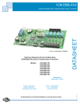
Enhanced Baby Bear Controller
Covered Models:
ICM-EBB-100
ICM-EBB-200
ICM-EBB-300
ICM-EBB-400 ICM-EBB-700
ICM-EBB-500
ICM-EBB-600
Divelbiss Corporation
9778 Mt. Gilead Road,
Fredericktown, Ohio 43019
Toll Free: 1-800-245-2327
Web: http://www.divelbiss.com
Email: [email protected]
2004007.8
Table of Contents
Manual Contents
Getting Started
How to Use this Manual........................................................................ 3
Configuring the ICM-EBB-XXX Target in EZ LADDER Toolkit................... 4
Loading the ICM-EBB-XXX Kernel.......................................................... 4
Getting to Know the ICM-EBB-XXX........................................................ 6
ICM-EBB-XXX Features
Programming Port................................................................................. 9
Watchdog LED....................................................................................... 9
Input Power........................................................................................... 9
Input Power LED.................................................................................. 10
Mounting & Dimensions...................................................................... 10
Digital Inputs....................................................................................... 11
Digital Outputs..................................................................................... 12
Counter Input...................................................................................... 12
General Purpose Serial Port................................................................. 13
Real Time Clock................................................................................... 15
CAN Networking Ports......................................................................... 15
I/O Expansion...................................................................................... 15
ICM-EBB-XXX Target Setting Options................................................... 17
Specifications....................................................................................... 17
WARNING!!
The ICM-EBB-XXX, as with other programmable controllers must not be used alone in
applications which could be hazardous to personnel in the event of failure of this device.
Precautions must be taken by the user to provide mechanical and/or electrical safeguards
external to this device. This device is NOT APPROVED for domestic or human medical use.
ICM-EBB-XXX User’s Manual
Document #: 2004007.8.pdf
Divelbiss Corporation • 9778 Mt. Gilead Road • Fredericktown, Ohio 43019 • 1-800-245-2327 • www.divelbiss.com
PAGE 1 of 17
Getting Started
This section explains how to read this manual and understand the symbols and information that it contains.
To begin using your Enhanced Baby Bear Controller, you will need to follow these steps:
• Install EZ LADDER Toolkit if not already installed (not included).
• Configure the Enhanced Baby Bear Controller in the EZ LADDER Toolkit Project Settings.
• Using purchased or self-made cables, connect the Input Power and Programming Port.
• Write a ladder diagram program.
• Download and run the program on the Enhanced Baby Bear Controller.
Refer to the appropriate sections of this manual for details on the above items.
Getting Started
How to Use this Manual
In this manual, the following conventions are used to distinguish elements of text:
BOLD
italic
SMALL CAPS
Denotes labeling, commands, and literal portions of syntax that must appear exactly as shown.
Used for variables and placeholders that represent the type of text to be entered by the user.
Used to show key sequences or actual buttons, such as OK, where the user clicks the OK button.
In addition, the following symbols appear periodically in the left margin to call the readers attention to specific details in the text:
Warns the reader of a potential danger or hazard associated with certain actions.
Appears when the text contains a tip that is especially useful.
Indicates the text contains information to which the reader should pay particularly close
attention.
All Specifications and Information Subject to Change without Notice
ICM-EBB-XXX User’s Manual
Document #: 2004007.8.pdf
Divelbiss Corporation • 9778 Mt. Gilead Road • Fredericktown, Ohio 43019 • 1-800-245-2327 • www.divelbiss.com
PAGE 3 of 17
Getting Started
Configuring the ICM-EBB-XXX Target in EZ LADDER Toolkit
Before you can program and use the ICM-EBB-XXX Controller, it must be configured as a target within the EZ LADDER Toolkit. For
help with installing or using EZ LADDER, please refer to the EZ LADDER User’s Manual.
1. In EZ LADDER, from the File Menu at the top, click PROJECT then SETTINGS. This will open the Project Settings Window.
Select Enhanced Baby Bear (128K) or Enhanced Baby Bear (256K) based on you actual model from the choices. Refer to Figure
1.1.
Figure 1.1 - Project Settings Window
2. A new window will open. Select the Model number of the Enhanced Baby Bear from the drop-down menu. Click OK. This
will close the Enhanced Baby Bear Properties dialog box.
3. Click OK. This will close the Project Settings Window, saving the EBB Model selected as the target for this ladder diagram
project.
Loading the ICM-EBB-XXX Kernel
THE ICM-EBB-XXX WILL NOT FUNCTION UNLESS
THIS STEP (KERNEL LOADING) IS COMPLETED.
The kernel is the firmware for the controller and to provide greater flexibility and reliability, Enhanced Baby Bear Controller shipments are factory shipped without a kernel. If this is a new unit from the factory, it will be necessary to load the kernel before a
ladder program can be downloaded. If the kernel is already loaded, this step is not required. To upgrade a kernel, see the EZ LADDER User’s Manual.
ICM-EBB-XXX User’s Manual
Document #: 2004007.8.pdf
Divelbiss Corporation • 9778 Mt. Gilead Road • Fredericktown, Ohio 43019 • 1-800-245-2327 • www.divelbiss.com
PAGE 4 of 17
Getting Started
To install the ICM-EBB-XXX’s kernel:
1. Verify the target has been configured (see Configuring the ICM-EBB-XXX Target in EZ LADDER Toolkit).
2. Connect the Programming cable(s) from the computer to the ICM-EBB-XXX. See Programming Port in the ICM-EBB-XXX Features
section.
3. Create a small one-rung program with a normally open (direct contact) and an output tied together. You may also open a preexisting program for the EBB. EZ LADDER version 1.0.4.4 and later includes a sub-directory (...EZ LADDER\Kernel Install Start Programs\)which has starter programs for each target to load the kernel. Choose GetStarted_ICM-EBB-128K.dld or GetStarted_ICMEBB-256K.dld based on the model number.
4. Click the
(Compile) button
5. Click the
(Monitor) button to change from the ‘Edit’ to ‘Monitor’ Mode.
6. Click the
(Connect) button to connect to the target. A dialog will appear automatically when no kernel is
loaded. If this dialog does not appear, click PROJECT then BOOTLOADER.
7. Click the BROWSE button and select the target’s kernel (by part number) located by default at C:\Program Files\EZ
Ladder\Kernel\
The following are kernel names and descriptions:
File Name
Description
EnhancedBabyBear_128k.dat
Kernel for 128K EBB
To be Used on (Partnumber)
ICM-EBB-100, ICM-EBB-200, ICM-EBB-300,
ICM-EBB-400, ICM-EBB-500,
ICM-EBB-600, ICM-EBB-700
EnhancedBabyBear_256k.dat
ICM-EBB-XXX User’s Manual
Kernel for 256K EBB
Document #: 2004007.8.pdf
Divelbiss Corporation • 9778 Mt. Gilead Road • Fredericktown, Ohio 43019 • 1-800-245-2327 • www.divelbiss.com
PAGE 5 of 17
Getting Started
8. Click the OPEN button to finish the kernel selection. Make sure the correct kernel is chosen.
9. Click the UPDATE TARGET button to install the kernel.
10. A dialog box will appear to show the status of the kernel installation. This could take a couple of minutes to install.
11. When the dialog windows close, the installation is complete. The Enhanced Baby Bear is ready to use and may be connected to
and programs may be downloaded.
The Enhanced Baby Bear Serial Number is factory set and cannot be changed.
Getting to Know the ICM-EBB-XXX
The ICM-EBB-XXX is available in multiple configurations based on the model number. While many features are offered, the actual
supported features depends on the model number. Figure 1.2 lists these features.
The ICM-EBB-XXX Controller is designed to provide powerful programmable features in an open-board format. Connections are
made via terminal blocks and connectors. Refer to Figure 1.3, as it illustrates the ICM-EBB-XXX.
ICM-EBB-XXX User’s Manual
Document #: 2004007.8.pdf
Divelbiss Corporation • 9778 Mt. Gilead Road • Fredericktown, Ohio 43019 • 1-800-245-2327 • www.divelbiss.com
PAGE 6 of 17
Getting Started
Flash Memory
On-Board I/O
Expansion I/O
Networking
Real Time
Clock
Program
Port
High
Speed
Counter
Model
128K
ICM-EBB-100
P
P
P
ICM-EBB-200
P
P
P
P
ICM-EBB-300
P
P
P
P
P
ICM-EBB-400
P
P
P
P
P
ICM-EBB-500
P
P
P
P
P
256K
5 Inputs
5 Outputs
ICM-EBB-600
P
P
ICM-EBB-700
P
P
EBB I/O
HDIO
OptiCAN
J1939
Serial/
Modbus
Port*
P
P
P
P
P
P
P
P
P
P
P
P
P
P
P
P
*Modbus/Serial Option requires optional Serial Port Module (specify RS232, RS422 or RS485).
Refer to the Specifications Section for details on operating parameters for all features.
Figure 1.2 - ICM-EBB-XXX Features
Battery
Real Time Clock
Input Power
Optional Serial Port
HDIO Port
Digital Outputs
12VDC or 10VAC
RS232/RS422/RS485
Power & Data
Relay, SPST, N.O.
EBB I/O Port
Power & Data
Program Port
CAN PORT
RS232/Null Modem
Power LED
Input Power
Digital Inputs
OptiCAN/J1939
10-30 VAC/VDC
Watchdog LED
High Speed Counter
Status Indicator
Up Count
Figure 1.3 - ICM-EBB-XXX
ICM-EBB-XXX User’s Manual
Document #: 2004007.8.pdf
Divelbiss Corporation • 9778 Mt. Gilead Road • Fredericktown, Ohio 43019 • 1-800-245-2327 • www.divelbiss.com
PAGE 7 of 17
ICM-EBB-XXX Features
This section explains the Enhanced Baby Bear Controller (ICM-EBB-XXX) hardware features, options and information regarding EZ
LADDER Toolkit for basic operation.
ICM-EBB-XXX Features
Programming Port
The ICM-EBB-XXX is programmed using its Programming Port (COM 0). This RS232 serial port is only to be used for programming
using Divelbiss EZ LADDER Toolkit software. This is not a general purpose port and may not be used in any other capacity than
programming the controller itself.
The Programming Port defaults to:
Baud: Parity: Data Bits: Stop Bits : 57600
None
8
1
To program the ICM-EBB-XXX, a null modem cable is required between the computer serial port and the controller’s programming
port. This cable can be self made, purchased locally or ordered from Divelbiss. Use Divelbiss Part Number 126-102860. Figure 2.1
provides the Programming Port Pinout.
RS232 Programming Port
Pin #
1
2
3
4
5
6
7
8
9
ID
--
RX
TX
--
GND
--
RTS
CTS
--
Description
Not Connected
Receive Data
Transmit Data
Not Connected
Signal Ground
Not Connected
Request To Send
Clear To Send
Not Connected
Figure 2.1 - Programming Port Pin-Out
Watchdog LED
The operating status of the ICM-EBB-XXX can be determined the by Watchdog LED. When the Watchdog LED is flashing at a slow
rate, approximately once per second, then there is no ladder program executing. When the Watchdog LED is flashing at a fast rate,
approximately 10 times per second, a program has been loaded and it is executing.
Should the Watchdog LED not flash at all, first check the input power. If the input power is correct and there is still no Watchdog
LED, contact Divelbiss Technical Services.
Input Power
The ICM-EBB-XXX may be powered using 10VAC or 12VDC. Apply power to CONN1 using the provided input power cable assembly
(PIMS-CA-6). Refer to the input power schematic for details. The transformer shown is optional.
The ICM-EBB-XXX is protected by a resetable fuse. If the fuse should open (the power LED is not illuminated), remove the input
power for 30 seconds and then reconnect the input power. The fuse will automatically reset when the power is removed.
ICM-EBB-XXX User’s Manual
Document #: 2004007.8.pdf
Divelbiss Corporation • 9778 Mt. Gilead Road • Fredericktown, Ohio 43019 • 1-800-245-2327 • www.divelbiss.com
PAGE 9 of 17
ICM-EBB-XXX Features
Figure 2.2 - Input Power Connections
Input Power LED
The ICM-EBB-XXX provides a visible status of the input power via the Input Power LED. When illuminated, the input power is ok.
Mounting & Dimensions
The ICM-EBB-XXX mounts to any sub-plate using standard hardware including standoffs and screws. See Figure 2.3.
Figure 2.3 - Mounting & Dimensions
ICM-EBB-XXX User’s Manual
Document #: 2004007.8.pdf
Divelbiss Corporation • 9778 Mt. Gilead Road • Fredericktown, Ohio 43019 • 1-800-245-2327 • www.divelbiss.com
PAGE 10 of 17
ICM-EBB-XXX Features
Digital Inputs
The ICM-EBB-XXX includes 5 on-board digital inputs. They are identified in EZ LADDER Toolkit and this manual as DI1.03 through
DI1.07. Each digital input can accept an input voltage of 10-30 VAC or DC. The inputs may be wired as either sinking or sourcing
and are wired through the provided terminal block (TS1). See Figure 2.4 for typical wiring diagrams for sinking and sourcing inputs.
The inputs are labeled on the printed circuit board as 0-4 (representing DI1.03 through DI1.07 respectively). As these inputs are
isolated, both the + and - terminals for each must be connected for the input to operate properly. For convenience, terminals labeled +V and C are provided. These terminals are quick wiring points to wire devices to the inputs. The +V is approximately 12VDC
while the C is the ground or common. See Figure 2.6.
To read a digital input status in a ladder diagram, place and connect the appropriate contact for your needs. The DIRECT CONTACT
and INVERTED CONTACT functions are used to read digital inputs in the ladder diagram. When placing the contact, verify you select
the correct input address (DI1.03 - DI1.07) from the provided drop-down menu. Depending upon the EZ LADDER version, these
variables may be created automatically (DI1_03 - DI1_07). If not automatically created, you must create them. Refer to the EZ
LADDER User’s Manual.
AC or +DC
Sourcing
Input
Device
ACC or -DC
Figure 2.4 - Typical Sinking Input Circuit
INPUT
AC or +DC
0
ACC or -DC
INPUT
0
Sinking
Input
Device
Figure 2.5 - Typical Sourcing Input Circuit
Figure 2.6 - Input Terminations
ICM-EBB-XXX User’s Manual
Document #: 2004007.8.pdf
Divelbiss Corporation • 9778 Mt. Gilead Road • Fredericktown, Ohio 43019 • 1-800-245-2327 • www.divelbiss.com
PAGE 11 of 17
ICM-EBB-XXX Features
Digital Outputs
The ICM-EBB-XXX includes 5 on-board digital outputs (relay). They are identified in the EZ LADDER Toolkit and this manual as
DO1.03 - DO1.07. These relay outputs are Form A (SPST) and Normally Open.
Commutating diodes or Metal Oxide Varistors (MOVs) should be installed on all output channels for noise immunity based on the
voltage being used (AC or DC). See Figure 2.7.
To control a digital output in a ladder diagram, place and connect the appropriate coil for your needs. The DIRECT COIL and INVERTED COIL functions are used to control digital outputs in the ladder diagram. When placing the coil, verify you select the correct output address (DO1.03 - DO1.07) from the provided drop-down menu. Depending upon the EZ LADDER version, these variables may
be created automatically (DO1_03 - DIO_07). If not automatically created, you must create them. Refer to the EZ LADDER User’s
Manual. All outputs connections are wired through the provided terminal block (TS3). See Figure 2.8.
AC Only
OUTPUT
LOAD
0
AC or +DC
DC Only
ACC or -DC
Figure 2.7 - Typical Output Circuits
Figure 2.8 - Output Terminations
Counter Input
The ICM-EBB-XXX provides an optional on-board counter input (model dependent). This is an up counter input that can operate up
to 100 KHz. It is ideal for connecting pulse output devices, such as flow meters and other sensors.
Figure 2.9 illustrates the counter input circuit. Figure 2.10 illustrates a typical sourcing input device (the device sources the voltage)
connected to the counter, while Figure 2.11 illustrates a typical sinking input device (the devices sinks the input to ground or common)connected to the counter.
ICM-EBB-XXX User’s Manual
Document #: 2004007.8.pdf
Divelbiss Corporation • 9778 Mt. Gilead Road • Fredericktown, Ohio 43019 • 1-800-245-2327 • www.divelbiss.com
PAGE 12 of 17
ICM-EBB-XXX Features
EBB COUNTER CIRCUIT
Opto-Coupler
+
-
Figure 2.9 - Counter Input Circuit
+V
+12/24VDC
+
SIG
GND
-
Figure 2.10 - Sourcing Counter Input
PULSE OUTPUT
DEVICE
PULSE OUTPUT
DEVICE
+12/24VDC
+
SIG
GND
-
Figure 2.11 - Sinking Counter Input
To use the high speed counter, you must use the CNTRMR function block. This block, when placed in the ladder diagram, will provide a drop-down menu to select channel 1. Refer to the EZ LADDER Toolkit User’s Manual for details on the CNTRTMR and other
function blocks. The High Speed Counter is always Channel 1.
General Purpose Serial Port
The ICM-EBB-600 and ICM-EBB-700 support an optional second serial port (COM 1). This serial port is a general purpose serial port
that supports serial printing. This port may also be used to communicate to a Modbus Master Device (the ICM-EBB-XXX is a Modbus
Slave). At this time, the general purpose serial port is an output device only as there is no software support to read a serial input.
This port may be factory ordered as ICM-EBB-RS232 (RS232), ICM-EBB-RS422 (RS422) or ICM-EBB-RS485 (RS485). This serial port
module plugs into and mounts to the ICM-EBB-XXX Controller. For mounting the serial port module to the ICM-EBB-XXX controller,
see Figure 2.12. For pin assignments, refer to Figure 2.13.
ICM-EBB-XXX User’s Manual
Document #: 2004007.8.pdf
Divelbiss Corporation • 9778 Mt. Gilead Road • Fredericktown, Ohio 43019 • 1-800-245-2327 • www.divelbiss.com
PAGE 13 of 17
ICM-EBB-XXX Features
Figure 2.12 - General Purpose Serial Port Mounting
RS232 Serial Port - ICM-EBB-RS232
RS422 Serial Port - ICM-EBB-RS422
Pin
ID
Description
1
TX-
Transmit Data -
2
-----
Not Connected
3
-----
Not Connected
4
RX-
Receive Data 5
GND Ground
6
RX+
Receive Data +
7
-----
Not Connected
8
-----
Not Connected
9
TX+
Transmit Data +
Pin
1
2
3
4
5
6
7
8
9
ID
-----
RX
TX
-----
GND
------
RTS
CTS
------
Description
Not Connected
Receive Data
Transmit Data
Not Connected
Ground
Not Connected
Request to Send
Clear to Send
Not Connected
Pin
1
2
3
4
5
ID
TX-
-----
-----
-----
GND
RS485 Serial Port - ICM-EBB-RS485
Description
Pin
ID
Transmit Data -
6
-----
Not Connected
7
-----
Not Connected
8
-----
Not Connected
9
TX+
Ground Description
Not Connected
Not Connected
Not Connected
Transmit Data +
Figure 2.13 - General Purpose Serial Port Pin Assignments
ICM-EBB-XXX User’s Manual
Document #: 2004007.8.pdf
Divelbiss Corporation • 9778 Mt. Gilead Road • Fredericktown, Ohio 43019 • 1-800-245-2327 • www.divelbiss.com
PAGE 14 of 17
ICM-EBB-XXX Features
Real Time Clock
The ICM-EBB-XXX includes an optional Real Time Clock. The real time clock (after set) provides Month, Day, Day of the Week, Year,
Hour, Minute and Second. The real time clock maintains time when power is lost via lithium battery.
The life of the battery for the real time clock generally has years of life before replacement is needed. Should the battery need to
be replaced, replace the battery with the same type and size as the original.
The battery is a Lithium Coin Cell, Type BR2325.
CAN Networking Ports
A CAN port is provided for networking including SAE J1939 and the Divelbiss proprietary OptiCAN Network.
The on-board CAN port is CAN 0. To use the ICM-EBB-XXX’s CAN port as either SAE J1939 or OptiCAN, it will be necessary to configure certain parameters. These parameters may be configured from the ICM-EBB-XXX Properties Window in the Project Settings. As
these settings vary greatly and are software based only, please refer to the EZ LADDER Toolkit User’s Manual for details on configuring, using and implementing CAN port networking including all relevant function blocks.
The CAN ports should be wired according to established practices for CAN networks. Figure 2.14 illustrates typical CAN Port connections.
Figure 2.14 - Typical CAN Port Connections
I/O Expansion
Certain models of the Enhanced Baby Bear Controller allow for I/O Expansion using one of two methods. Depending upon the
model, the controllers I/O may be expanded using the Divelbiss High Density I/O product line (cables and I/O cards) or the Enhanced Baby Bear I/O Expansion. The High Density I/O products connect using a cable set to the controller and are DIN rail
mounted. The Enhanced Baby Bear I/O mounts to the controller in a stacking configuration.
ICM-EBB-XXX User’s Manual
Document #: 2004007.8.pdf
Divelbiss Corporation • 9778 Mt. Gilead Road • Fredericktown, Ohio 43019 • 1-800-245-2327 • www.divelbiss.com
PAGE 15 of 17
ICM-EBB-XXX Features
High Density I/O Expansion
The ICM-EBB-500 and ICM-EBB-700 I/O can be expanded with up to an additional 120 Inputs and 120 Outputs using the ICM-HDIOXX series I/O Expander boards. The ICM-HDIO-XX series provides a wide range of input and output types and voltages.
High Density I/O Expanders use the ICM-EBB-XXX’s CONN6 (for data) and CONN3 (for power). These connections are made via
cables. The ICM-HDIO-XX boards are din rail mounted. Their addressing is set via on-board jumpers.
The High Density I/O uses the same type of I/O assignments as the Enhanced Baby Bear where either DI or DO for Digital Input or
Digital Output, the Page Number(0-7) and then actual I/O point (.00-.15)
The I/O addressing for the ICM-HDIO-XX I/O are as follows:
Digital Inputs:
DI0.00 - DI0.15
DI1.00 - DI1.07 are used on board the ICM-EBB-XX and are NOT valid.
DI1.08 - DI7.15
Digital Outputs: DO0.00 - DO0.15
DO1.00 - DO1.07 are used on board the ICM-EBB-XX and are NOT valid.
DO1.08 - DO7.15
Enhanced Baby Bear I/O Expansion
The ICM-EBB-400 and ICM-EBB-600 I/O can be expanded with an additional 8 Inputs rated 10-32 VDC and 8 Relay Outputs using
the ICM-EBB-IO-54RE-P.
Baby Bear Expanders use the ICM-EBB-XXX’s CONN8. The ICM-EBB-IO-54P connects directly to CONN8 and is mounted to the ICMEBB-XXX (stacking configuration). The ICM-EBB-IO-54RE-P is factory addressed and cannot be changed.
The Enhanced Baby Bear I/O uses the same type of I/O assignments as the Enhanced Baby Bear where either DI or DO for Digital
Input or Digital Output, the Page Number(1) and then actual I/O point (.08-.15)
The I/O addressing for the ICM-EBB-IO-54P is always as follows:
Digital Inputs:
DI1.08 - DI1.15
Digital Outputs: DO1.08 - DO1.15
For mounting the Enhanced Baby Bear with a stacking I/O Expander, please see the Mounting and Dimensions section this manual.
ICM-EBB-XXX User’s Manual
Document #: 2004007.8.pdf
Divelbiss Corporation • 9778 Mt. Gilead Road • Fredericktown, Ohio 43019 • 1-800-245-2327 • www.divelbiss.com
PAGE 16 of 17
ICM-EBB-XXX Features
ICM-EBB-XXX Target Setting Options
To use some of the function blocks and features on the ICM-EBB-XXX, it may be required to configure additional target properties in
the Project Settings Dialog Box. Click PROJECT then SETTINGS. With the Enhanced Baby Bear model selected, click PROPERTIES.
The following are items that must be configured in the Enhanced Baby Bear Project Settings, Properties Dialog.
J1939 Properties
This is where SAE J1939 Communications is enabled and configured. Refer to the J1939 section of the EZ
LADDER Manual.
OptiCAN Properties
This is where OptiCAN Communications is enabled and configured. Refer to the OptiCAN section of the
EZ LADDER Manual.
Serial Print Properties
This is used if the Serial Print function block is to be used to transmit data to an external device using the
General Purpose Serial port. The serial port is configured here.
Specifications
Processor:
Memory:
Serial Ports:
Networking:
Digital Inputs:
Digital Inputs:
Counters:
I/O Expansion:
Input Power:
Operating Temp:
Program Language:
Real Time Clock:
Dimensions:
Mounting:
Type:
Storage Temperature:
ICM-EBB-XXX User’s Manual
PLC on a ChipTM
128K/256K Flash, 8K/12K RAM, 2K/4K EEPROM (Model Dependent)
1 Programming Port
1 Optional Multipurpose Port, RS232, RS422 or RS485 (Sold Separately), Supports Modbus Slave
1 CAN Port for Divelbiss OptiCAN or J1939 Communications
5 Inputs rated 10-30 VAC/VDC., Optically Isolated, with Indicator LEDs
Typical Turn On: 4.5 VAC/VDC
Typical Turn Off: 3.5 VAC/VDC
Typical Input Current: 9mA @ 30VAC/VDC
5 Relay Outputs, Normally Open (Dry Contacts), with Indicator LEDs
Relay Ratings: 1/8HP, 125VAC/250VAC, 5A @ 30VDC/250VAC
1 High Speed Counter Channel, Count Up, Optically Isolated, 100KHz Max. Frequency.
Up to 120 total Inputs & 120 total Outputs using High Density I/O Line or
12 total Inputs & 12 total Outputs using Enhanced Baby Bear I/O Expansion.
10VAC or 12VDC (115VAC with Optional Transformer)
-40-60° C
Ladder Logic using Divelbiss EZ LADDER Toolkit.
Optional, Moth, Day, Year, Day of Wee, Hour Minute Second
Battery Type, Lithium Coin, BR2325 (3VDC)
4.00” Wide x 8.75” Length x 1.04” Tall.
Panel Mount (requires standoffs or other hardware - Sold Separately)
Open Board
-40-60° C
Document #: 2004007.8.pdf
Divelbiss Corporation • 9778 Mt. Gilead Road • Fredericktown, Ohio 43019 • 1-800-245-2327 • www.divelbiss.com
PAGE 17 of 17