1
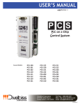
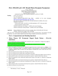
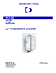
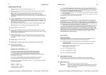
PLC on a CHIP Control System
PCS
Programs
in Ladder
Logic
PCS Technical
User’s Manual
PLC on a Chip Patent 7,299,099
REV .2
Smart Parts for Managing
Automation
9778 Mt. Gilead Rd.
Fredericktown, OH 43019
Toll Free: 1-800-245-2327
Web: http://www.divelbiss.com
Email: [email protected]
2006004.2
Table of Contents
TABLE OF CONTENTS
Table of Contents
Page 2
Getting Started
How to Use this Manual
Part Numbers & Configurations
Configuring the PCS Target in EZ LADDER
Configuring PWM Properties
Page
Page
Page
Page
Page
3
4
4
5
6
PCS Features
Getting to Know the PCS
PCS Mounting
PCS Input Power
Watchdog LED
Power LED
Programming Port
CAN Ports
Real Time Clock
High Density I/O Port
Counter Inputs
Synchronous Serial Interface (SSI)
Multi-purpose Serial Port
Analog Inputs
Analog Outputs
PWM Outputs
Specifications
Page
Page
Page
Page
Page
Page
Page
Page
Page
Page
Page
Page
Page
Page
Page
Page
Page
8
9
10
11
11
11
12
12
13
14
15
15
16
16
17
18
19
WARNING!
The PCS-XXX, as with programmable controllers, must not
be used alone in applications which would be hazardous to
personnel in the event of failure of this device. Precautions
must be taken by the user to provide mechanical and/or
electrical safeguards external to this device. This device is
NOT APPROVED for domestic or human medical use.
PCS-XXX User’s Manual
Document #: 2006004.1.pdf
Page 1 of 18
Divelbiss Corporation 9778 Mt. Gilead Rd. Fredericktown, Ohio 43019 1-800-245-2327 www.divelbiss.com
GETTING STARTED
This section explains how to read this manual and understand the symbols as well as understanding how PCS
part numbers are configured.
Getting Started
HOW TO USE THIS MANUAL
In this manual, the following conventions are used to distinguish elements of text:
BOLD
Denotes labeling, commands, and literal portions of
syntax that must appear exactly as shown.
italic
Used for variables and placeholders that represent the type of text
to be entered by the user.
SMALL CAPS
Used to show key sequences or actual buttons, such as
the OK button.
OK,
where the user clicks
In addition, the following symbols appear periodically in the left margin to call the readers attention to specific details in
the text:
Warns the reader of a potential danger or hazard that is associated
with certain actions.
Appears when the text contains a tip that is especially helpful.
Indicates that the text contains information to which the reader
should pay particularly close attention.
PART NUMBERS & ORDERING INFORMATION
PCS Controller part numbers are configured using options. Each part number contains a Base System, a Serial Port
Option and Analog I/O Option.
Model Number Configuration:
1
BASE SYSTEM
2
PCS
-
2
1
1
2
MULTI-PURPOSE SERIAL PORT
1
3
3
ANALOG I/O
1
256K PLC on a Chip Processor, High
Density I/O Interface and Real Time Clock
0
No Serial Port Installed
0
No Analog I/O Installed
1
RS232 Serial Port Installed
1
2
256K PLC on a Chip Processor, High
Density I/O Interface, Real Time Clock, 2
CAN Network Ports, SSI Port, 2 High
Speed Counter Inputs.
6 Analog Inputs rated 0-5VDC, 4 Analog
Outputs rated 0-5VDC & 2 PWM Outputs.
2
RS422 Serial Port Installed
2
6 Analog Inputs rated 0-20mADC, 4 Analog
Outputs rated 0-20mADC & 2 PWM Outputs.
3
RS485 Serial Port Installed
PCS-XXX User’s Manual
Document #: 2006004.1.pdf
Page 3 of 18
Divelbiss Corporation 9778 Mt. Gilead Rd. Fredericktown, Ohio 43019 1-800-245-2327 www.divelbiss.com
Getting Started
CONFIGURING THE PCS TARGET IN EZ LADDER
Before you can program and use the PCS Controller, it must be configured as a target within EZ LADDER. For help with
installing or using EZ LADDER, please refer to the EZ LADDER User’s Manual.
In EZ LADDER, select PROJECT....SETTINGS. This will open the Project Settings Window. Select “PCS-1XX” or “PCS2XX” for the target depending upon the first number of the PCS Model #.. Figure 1.1 show the Project Settings Window.
Figure 1.1
Once the “PCS-XXX” target is selected, you must identify which exact model will be used. Click the PROPERTIES button.
A drop down dialog box will open with models of PCS-XXX to select from. Select the model that will be used. See
Figure 1.2.
Figure 1.2
Note: Checkboxes next to features will remind you of the options installed on the selected model.
If a model is chosen that includes PWM and Analog Outputs, the PWM must be configured to use PWM or Analog
Outputs. If you do not have a model with PWM, you may skip the next part of the configuration by clicking OK to close
the Target Properties and click OK to close the ProjectSettingsForm.
PCS-XXX User’s Manual
Document #: 2006004.1.pdf
Page 4 of 18
Divelbiss Corporation 9778 Mt. Gilead Rd. Fredericktown, Ohio 43019 1-800-245-2327 www.divelbiss.com
Getting Started
CONFIGURING PWM PROPERTIES
PCS Controllers with Analog Options include 6 hardware pulse width modulation channels (PWM). Two channels are for
PWM only and the other four channels are used as analog outputs.These channels must be installed before they can
controlled in the EZ LADDER diagram.
To install PWM Outputs in the target configuration:
1. Use the menu, select PROJECT....SETTINGS. The ProjectSettingsForm dialog will open. Select
the target.
2. Click the PROPERTIES button.
3. Click the PWM PROPERTIES button.
4. The PWM Properties window will open. See Figure 1.3.
Figure 1.3
5. Click the ADD button in the PWM Properties window.
6. In the ADD PWM dialog, select the channels to install. The channels are as follows:
AOUT Channel
AOUT Channel
AOUT Channel
AOUT Channel
0
1
2
3
-
Install
Install
Install
Install
PWM
PWM
PWM
PWM
0
1
2
3
PWM Channel 1 - Install PWM 4
PWM Channel 2 - Install PWM 5
Note: Do not install PWM6 or PWM7 as they are not used.
7. Click
OK
PCS-XXX User’s Manual
to close the ADD PWM dialog. The next step is configuring the frequencies.
Document #: 2006004.1.pdf
Page 5 of 18
Divelbiss Corporation 9778 Mt. Gilead Rd. Fredericktown, Ohio 43019 1-800-245-2327 www.divelbiss.com
Getting Started
8. Enter the desired frequency for Clock A and Clock B (if installed). The PCS has 6 available PWM Channels.
Two are used as PWM outputs and 4 are used as analog outputs. These channels are either controlled with
Clock A or Clock B. This allows two different PWM frequencies. The Minimum and Maximum frequencies
are displayed in the PWM Properties dialog. The frequency for Clock A and Clock B must be in this range.
The ACTUAL FREQUENCY is what will be seen on the actual PWM hardware output channels (as close as
possible to the desired frequency; this is due to limitations of the hardware).
Figure 1.4
9. Click
OK
to close the PWM Properties and save the changes.
11. Click
OK
to close the Target Properties and save the changes.
12. Click
OK
to close the ProjectSettingsForm dialog and save the changes.
The PWM channels are now ready for use using the PWM and PWM_FREQ functions. Refer to EZ
LADDER Manual - Section 10 for details on using and configuring these functions. For more detail on using
the PWM outputs as Analog outputs, refer to Page 17 of this manual.
PCS-XXX User’s Manual
Document #: 2006004.1.pdf
Page 6 of 18
Divelbiss Corporation 9778 Mt. Gilead Rd. Fredericktown, Ohio 43019 1-800-245-2327 www.divelbiss.com
PCS FEATURES
This section describes the PCS hardware features and options including using EZ LADDER to operate the hardware.
PCS Features
GETTING TO KNOW THE PCS
Multi-purpose
Serial Port
RS232, RS422 or
RS485
Synchronous
Serial Interface
(SSI)
High Density I/O
Port (HDIO)
CAN O Network
Port
Digital I/O Expansion
Watchdog LED
Programming
Port
CAN 1 Network
Port
RS232 Null Modem
Power LED
Input Power is OK
2 Channel High
Speed Counter
Up to 100 KHz
Input Power
10VAC or 12-24VDC
Figure 2.1 - PCS Features
PCS-XXX User’s Manual
Document #: 2006004.1.pdf
Page 8 of 18
Divelbiss Corporation 9778 Mt. Gilead Rd. Fredericktown, Ohio 43019 1-800-245-2327 www.divelbiss.com
PCS Features
PCS MOUNTING
The PCS mounts to industry standard DIN Rail.
To mount the PCS:
1. Ensure the Din Rail Mounts are pushed in towards the center of the PCS until they snap into position (if not in
position already).
2. Angle the PCS with the left side down until the din rail mounts are past the din rail as shown.
3. Using a screw driver, hold open the Din Rail Release and push the PCS flat against the din rail.
4. Remove the tension from the screwdriver and let the Din Rail Release close.
The PCS should now be securely mounted to the din rail.
3.55”
2.3”
PLC ON A CHIP TM
CONTROL SYSTEM
CORPORATION
6.22”
MODEL #:
SERIAL #:
Din Rail
Mounts
Din Rail
on a chip
TM
Embedded
PCS MOUNTING - END VIEW
Programmable
Logic Controller
PCS MOUNTING - TOP VIEW
Din Rail Release
Figure 2.2 - Mounting the PCS
To release the PCS from the din rail:
1 Use a screw driver, hold open the Din Rail Release and pull the PCS off the din rail at an angle until the Din Rail
Mounts are free.
2. Remove the tension from the screwdriver and let the Din Rail Release close.
PCS-XXX User’s Manual
Document #: 2006004.1.pdf
Page 9 of 18
Divelbiss Corporation 9778 Mt. Gilead Rd. Fredericktown, Ohio 43019 1-800-245-2327 www.divelbiss.com
PCS Features
PCS INPUT POWER
The PCS may be powered using 10 VAC or 12-30 VDC. Apply power to CONN1 using the provided input power cable
assembly (PIMS-CA-6). Refer to the input power schematic for details. The transformer shown is optional.
Divelbiss recommends a step down transformer, 110 VAC to 10 VAC, @ 2A. The transformer may be purchased from
Divelbiss Corporation ( 115VAC Primary: 109-101153, 230VAC Primary: 109-100924)
Figure 2.3 - Input Power Connections
WATCHDOG LED
The operating status of the PCS can be determined the by Watchdog LED. When the Watchdog LED is flashing at a
slow rate, approximately once per second, then there is no program executing. When the Watchdog LED is flashing at a
fast rate, approximately 10 times per second, a program has been loaded and it is executing.
Should the Watchdog LED not flash at all, first check the input power and Power LED. If the input power is correct and
there is still no Watchdog LED, contact Divelbiss Technical Services.
POWER LED
When the Power LED is illuminated, there is sufficient input voltage to allow for proper operation of the PCS.
The PCS is protected by a “resettable” fuse. If the fuse should open (the power LED is not illuminated), remove the
input power for 30 seconds and then reconnect the input power. The fuse will automatically reset when the power is
removed.
Please note: while the PCS controller’s input power is not polarity sensitive for operation, the PWR LED is polarity sensitive. If the PWR LED does not operate, but the unit is functional, swap the input power connections.
PCS-XXX User’s Manual
Document #: 2006004.1.pdf
Page 10 of 18
Divelbiss Corporation 9778 Mt. Gilead Rd. Fredericktown, Ohio 43019 1-800-245-2327 www.divelbiss.com
PCS Features
PROGRAMMING PORT - COM 0
The PCS is programmed using its Programming Port (COM 0). This RS232 serial port is only to be used for programming using Divelbiss’ EZ LADDER. The Programming Port defaults to 57600,N,8,1. This is not a general purpose port. A null modem cable should be used to connect with COM 0. This cable may be purchased from Divelbiss
(use Part Number: ICM-CA-34).
RS232 Serial Port Module
Pin
ID
1
2
3
4
5
6
7
8
9
-RX
TX
-GND
-RTS
CTS
--
Description
No Connect
Receive Data
Transmit Data
No Connect
Signal Ground
No Connect
Request To Send
Clear To Send
No Connect
Figure 2.4 - PROGRAMMING PORT - COM 0 Pin-Out
CAN PORTS
The PCS provides an two optional on-board CAN bus interface ports. These CAN ports support the Divelbiss OptiCan
Network and J1939 communications. The CAN ports are connected as shown in Figure 2.5.
CAN BUS
DEVICE 2
CAN BUS
DEVICE 1
LOW
Typical
120
Ohms
Typical
120
Ohms
PCS CAN
PORT
HI
SHD
Figure 2.5 - Typical CAN Connections
PCS-XXX User’s Manual
Document #: 2006004.1.pdf
Page 11 of 18
Divelbiss Corporation 9778 Mt. Gilead Rd. Fredericktown, Ohio 43019 1-800-245-2327 www.divelbiss.com
PCS Features
REAL TIME CLOCK
All PCS models include a Real Time Clock. The real time clock (after being set) provides the Month, Day, Day of the
Week, Year, Hour, Minute and Second. The real time clock maintains time when power is lost via lithium battery. The
Real Time Clock may be accessed using the EZ LADDER functions: GETDATE, GETTIME, SETTIME, SETDATE.
The life of the battery for the real time clock generally has years of life before replacement is needed. Should the battery need to be replaced, replace the battery with the same type and size as the original.
The battery is a Lithium Coin Cell, Type CR2025.
To replace the battery
(see Figure 2.6):
1. Remove the PCS from din rail (if necessary).
2. Turn the PCS upside down to gain access to the bottom (mounted side).
3. Using a small flat screwdriver, gently pry and release the latches on the bottom of the PCS. This will allow
the bottom insert to be removed giving access to the internal PCS controller printed circuit card.
4. Turn the PCS right side up. The printed circuit cards should easily come out. If they do not slide out easily,
check for mouting latches or tabs that may be “binding” the printed circuit cards in place.
5. Slide the battery from the holder and replace with a new battery. Make sure the new battery is in correctly.
The Positive (+) should be visible. See Figure 2.7.
Figure 2.6 - Disassembly - Bottom
Figure 2.7 - Real Time Clock Battery Replacement
PCS-XXX User’s Manual
Document #: 2006004.1.pdf
Page 12 of 18
Divelbiss Corporation 9778 Mt. Gilead Rd. Fredericktown, Ohio 43019 1-800-245-2327 www.divelbiss.com
PCS Features
HIGH DENSITY I/O PORT (HDIO)
The PCS can accept up to 128 Inputs and 128 Outputs using the ICM-HDIO-XX series I/O Expander boards. The ICMHDIO-XX series provides a wide range of input and output types and voltages. The +VA and the 5VDC supply power to
the HDIO boards are powered from the PCS.
When using a step-down transformer to provide the 10VAC input power, the maximum output power on CONN3 is +VA
(12VDC) @ .5A (6 Watts) and 5VDC @ .5A.
When using a DC supply to power the PCS controller, the output power on CONN 3 will be 5VDC maximum @ .5A and
the +VA (equal to the input power) @ 6 Watts maximum.
Please note: Expander board relay coil operating voltage must be within range of the input power to the PCS when
using DC power sources or damage to the relays may result due to overvoltage. Ensure proper relays are installed.
High Density I/O Expanders use the PCS High Density I/O Port (CONN6 for data and CONN3 for power). These connections are made via cables. The ICM-HDIO-XX boards are din rail mounted and have configurable addresses.
The legal I/O addressing for the ICM-HDIO-XX is as follows:
Digital Inputs:
DI0.00 - DI7.15
Digital Outputs: DO0.00 - DO7.15
The Digital I/O may be accessed using the EZ LADDER objects: DIRECT COIL, INVERTED COIL, DIRECT CONTACT,
INVERTED CONTACT.
+ 1/9
+ 2/10
TM
+ 5/13
+ 5/13
+ 6/14
+ 6/14
+ 7/15
+ 7/15
+ 4/12
+ 4/12
+ 3/11
PLC ON A CHIP
CONTROL SYSTEM
+ 3/11
+ 1/9
+ 2/10
+ 0/8
+ 0/8
+12V COM+5V
ICM-HDCA-1X
CABLE
C OR POR ATION
MODEL #:
SERIAL #:
HIGH DENSITY I/O BOARD (HDIO)
on a chip
TM
Embedded
Programmable
Logic Controller
Figure 2.8 - High Density I/O Connections
PCS-XXX User’s Manual
Document #: 2006004.1.pdf
Page 13 of 18
Divelbiss Corporation 9778 Mt. Gilead Rd. Fredericktown, Ohio 43019 1-800-245-2327 www.divelbiss.com
PCS Features
COUNTER INPUTS
The PCS provides two optional on-board counter inputs (model dependent). These are up counter inputs with capabilites to 100 KHz. It is ideal for connecting flowmeters and other pulse output devices and sensors. The High Speed
Counter Inputs use the EZ LADDER function: CNTRTMR.
Typical High Speed Counter connections are shown in Figure 2.9. The counter is optically isolated to provide immunity
from noise and interference.
Isolated High Speed
Counter Input
SHD
Shield
PULSE OUTPUT
DEVICE
Opto-Isolator
+DC (12V)
+CNT
-CNT
-DC
Figure 2.9 - Typical Counter Input Connections
SYNCHRONOUS SERIAL INTERFACE - SSI
The PCS provides a Graycode SSI interface for absolute encoders. The SSI interface uses the EZ LADDER function:
GC_SSI. When functioning, the GC_SSI block returns an integer value representing the Graycode reading from the
encoder. This is read serially, converted from Graycode to a binary number then returned to the block as an Integer output.
+D
+DATA
-DATA
+CLOCK
-CLOCK
-D
+C
TM
PLC ON A CHIP
CONTROL SYSTEM
-C
SHD
SHIELD
CORPORATION
Figure 2.10 - Typical SSI Connections
PCS-XXX User’s Manual
Document #: 2006004.1.pdf
Page 14 of 18
Divelbiss Corporation 9778 Mt. Gilead Rd. Fredericktown, Ohio 43019 1-800-245-2327 www.divelbiss.com
PCS Features
MULTI-PURPOSE SERIAL PORT - COM 1
The PCS can be purchased with an optional second serial port (multi-purpose port). Factory installed, this port may be
ordered as an RS232, RS422 or an RS485 interface and supports baud rates to 115.2K. The Multi-purpose Port is also
Modbus slave compatable. The Multi-purpose Serial Port uses Modbus or the EZ LADDER function: SERIAL_PRINT.
RS232 Serial Port Module
Pin
ID
1
2
3
4
5
6
7
8
9
-RX
TX
-GND
-RTS
---
Description
No Connect
Receive Data
Transmit Data
No Connect
Signal Ground
No Connect
Request To Send
No Connect
No Connect
RS422 Serial Port Module
Pin
ID
1
2
3
4
5
6
7
8
9
TX--RXGND
RX+
--TX+
Description
Transmit Data (-)
No Connect
No Connect
Receive Data (-)
Signal Ground
Receive Data (+)
No Connect
No Connect
Transmit Data (+)
RS485 Serial Port Module
Pin
ID
Description
1
2
3
4
5
6
7
8
9
TX---GND
---TX+
Data (-)
No Connect
No Connect
No Connect
Signal Ground
No Connect
No Connect
No Connect
Data (+)
Figure 2.11 - COM 1 - Multi-purpose Port Pin-Outs
ANALOG INPUTS
The PCS may be purchased with optional factory installed analog inputs. These analog inputs are factory set for 05VDC or 0-20mADC with 10-bit resolution and are buffered.
The legal addressing for the Analog Inputs is as follows: AN0 - AN5.
Analog inputs are ‘read’ as variables. To use an analog input in the ladder diagram, create a new variable and in the
VAR I/O Num, enter the analog channel address. See Figure 2.12.
Figure 2.12 - Add Variable - Analog Input
When the variable is used in the program, the analog signal will be represented digitally by an integer value of 0-1023
(where 0 is the low end of the scale - approximately 0VDC or 0mADC and 1023 is the high end of the scale -approximately 5VDC or 20mADC). These are raw values; therfore any conditioning (averaging, calibration, etc) must be done
in the ladder diagram.
Refer to Figure 2.13 for analog input pin assignments and connections.
PCS-XXX User’s Manual
Document #: 2006004.1.pdf
Page 15 of 18
Divelbiss Corporation 9778 Mt. Gilead Rd. Fredericktown, Ohio 43019 1-800-245-2327 www.divelbiss.com
PCS Features
Figure 2.13 - Analog Input Pin Assignments & Typical Wiring Diagram Connections
ANALOG OUTPUTS
The PCS may be purchased with optional factory installed analog outputs. These analog outputs are factory set for 05VDC or 0-20mADC with 8 -bit resolution. These terminals are labeled AOUT0 through AOUT3.
The PCS analog outputs are controlled in the ladder diagram using the PWM function. The PWM channels are converted to voltage or current depending upon the PCS model. The PCS must have the PWM channels configured in EZ
LADDER’s Target Configuration. See Page 6 for configuring the target to use the PWM channels. Figure 2.14 is an
example program using the PWM function to control terminal AOUT0. Figure 2.15 is a typical connection diagram.
Changing the PWM channel ‘frequency’ (Target Configuration) and the PWM function block’s ‘duty cycle’ will change the
analog output’s actual value. You may have to adjust settings several times to meet your desired output. A typical
beginning point would be a PWM frequencey of 2Khz.
The PWM channel is set to 0 with the
PWM0 configured for 2Khz.
Changing the ‘DutyCycle’ variable value
changes the actual analog output value.
Duty Cycle
.4%
51.2%
100%
Output
.4% of total Span
51.2% of total Span
Full Output 100% Span
Figure 2.14 - Using PWM to Control Analog Outputs
PCS-XXX User’s Manual
Document #: 2006004.1.pdf
Page 16 of 18
Divelbiss Corporation 9778 Mt. Gilead Rd. Fredericktown, Ohio 43019 1-800-245-2327 www.divelbiss.com
PCS Features
Figure 2.15 - Analog Output - Typical Wiring Diagram
PWM OUTPUTS
The PCS provides 2 optional PWM outputs. The following specifications apply to the PWM outputs. A PCS-CA-PWM
cable is provided to connect PWM channels to off-unit devices.
-Open Drain,
- Maximum Switch Voltage: 24VDC
- Maximum Sink Current: 10mA
- Maximum Saturation Voltage: 0.3V @ 0.5mA
- Maximum Frequency: 10KHz @ 50:50 Duty Cycle
- Minimum Duty Cycle Increment: 0.4%
The PCS PWM outputs are controlled in the ladder diagram using the PWM and PWM_FREQ functions. The PCS must
have the PWM channels configured in EZ LADDER’s Target Configuration. See Page 6 for configuring the target to use
the PWM channels. Figure 2.16 shows the PWM connector and pin-out. Figure 2.17 shows a typical PWM circuit.
PIN
1
2
3
4
5
6
7
8
9
10
DESCRIPTION
PWM CH 5 -V
PWM CH 5 SIGNAL
PWM CH 5 +V
PWM CH 4 -V
PWM CH 4 SIGNAL
CH 4 +V
Not PWM
Connected
Not Connected
Not Connected
Not Connected
Not Connected
Figure 2.16 - PWM Pin Assignments
PCS-XXX User’s Manual
Document #: 2006004.1.pdf
Page 17 of 18
Divelbiss Corporation 9778 Mt. Gilead Rd. Fredericktown, Ohio 43019 1-800-245-2327 www.divelbiss.com
PCS Features
+V (External Voltage Source)
PULL UP
RESISTORS
(If Required)
PCS PWM
OUTPUT
CONNECTOR
6
PWM Channel 4 Signal to
Load Device Circuitry
5
4
3
PWM Channel 5 Signal to
Load Device Circuitry
2
1
COMMON
(External Voltage Source)
Figure 2.17 - Typical PWM Circuit
SPECIFICATIONS
Processor:
Memory:
Serial Ports:
Networking:
Digital I/O:
Real Time Clock:
Counters:
Analog Inputs:
Analog Outputs:
PWM Outputs:
Power Requirements:
Operating Temp:
I/O POWER:
Program Language:
Dimensions:
Mounting:
Type:
Temperature:
PCS-XXX User’s Manual
PLC on a ChipTM
256K Flash, 12K RAM
2 Serial Ports - 1 RS232 Programming Port (Max baud: 57.6K);
1 RS232/RS422/RS485, (Max Baud:115.2K). Supports Modbus Slave
2 CAN Ports, Supports Divelbiss OptiCan, J1939
Up to total 128 Inputs and 128 Outputs using High Density I/O
Time of Day, Day, Month, Year & Day of Week
2 Channels, Count Up, 100KHz Max.
6 Channels, 10-bit Resolution, rated 0-5VDC or 0-20mADC
4 Channels, 8-bit Resolution, rated 0-5VDC or 0-20mADC
2 Channels Open Collector Output 1.436 Hz to 47.058KHz
115VAC with Optional Transformer, 10 VAC or 10-30VDC
0-60º C
With 10VAC Power, +VA (12VDC) @ .5A Max, 5VDC @ .5A Max.
With DC Input, +VA (equal to power in) @ 6 Watts Max, 5VDC @ .5A Max.
Ladder Logic using Divelbiss EZ LADDER.
3.6” Wide x 6.2” Length x 2.3” Tall.
DIN Rail Mount
Enclosed, Plastic Housing
0-60ºC
Document #: 2006004.1.pdf
Page 18 of 18
Divelbiss Corporation 9778 Mt. Gilead Rd. Fredericktown, Ohio 43019 1-800-245-2327 www.divelbiss.com