1
System Description
Overview
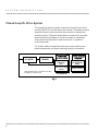
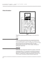
Typical electronic linear motion control systems consist of the
following elements:
Motor: Provides the torque and speed necessary for an actuator to
meet application requirements.
Drive: Converts the signal received from the controller or PLC to
actually move the motor. In addition, the drive must convert the
local power source (typically 115 Vac, 60 Hz) to the power input
required by the motor. The power ratings (watts) of the motor and
the drive must match the peak and RMS requirements of the
application.
Controller: Features I/O connections to receive inputs from a
programmable logic controller (PLC) or other operator interface and
convert them to output signals to the drive module to properly
control the motor and to achieve the required motion profile(s)
Operator Interface: An optional device used by the system operator
to program tr signal the controller remotely.
The performance of an electric linear actuator system is determined
by the type of control system used with the actuator (i.e. dc openloop brush servo, stepper, or ac brushless servo). In general, dc
systems represent a low-cost, mature technology easily applied to
meet basic linear motion needs.
3