1
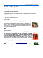
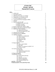
8 Channel USB GPIO Module
User Guide
www.numato.com
Rev 7
Get in touch with us!
Please feel free to send a mail to one of the mail IDs below or use the Contact Us page at
http://www.numato.com to drop us a quick message.
Technical Help
Got technical questions? Please write to [email protected]
Sales Team
Questions about making payments, volume discounts, academic/open source discounts, purchase
orders and quotes? Please write to [email protected]
Webmaster
Questions/Suggestions about our website? Please write to [email protected]
Like us on Facebook! https://www.facebook.com/numato
Visit our blog http://www.numato.cc for news, updates and specials.
Mailing Address
Numato Systems Pvt Ltd
2nd Floor, # 11, Seekan Heights
Phase-2, Electronics City
Bangalore, KA -560100
India
* Mail orders, phone orders and direct pick up are not available at this time. Please visit our online store to place your order. Estimated shipping time to
your address will be displayed in the shopping cart before checkout.
You may use, modify or share this publication or part of thereof adhering to Creative
Commons Attribution-ShareAlike 3.0 Unported (CC BY-SA 3.0) License.
See complete license text at http://creativecommons.org/licenses/by-sa/3.0/
All trademarks are property of their respective owners.
1
8 Channel USB GPIO Module – User Guide
Introduction
Numato Lab's 8 Channel USB GPIO Module is a versatile product for controlling electrical and
electronic devices remotely from a PC over USB link. Ease of use and wider operating system
compatibility are the primary goals behind this product's design. Built in USB to serial conversion
allows the module to be used without any USB specific knowledge. This simplicity allows use of offthe-shelf Terminal Emulation programs such as Hyper Terminal and PUTTY for controlling the module
with a simple set of human readable commands. For power users, this module can be controlled by
writing programs in various programming languages.
Some of the possible uses of this module include
• Home Automation
• Lighting Control
• Garden Equipment Control
• Industrial Automation
• Test Fixtures
• DIY and Hobby
This product is compatible with the following operating systems.
• Windows XP and later
• Linux
• Mac
• And any other operating system that supports USB CDC devices.
And these are some of the languages that can be used for programming.
• C/C++
• Visual Basic (VB6, VB2008, VB2010 express and other editions)
• Visual Basic for Applications (Microsoft Office VBA)
• Perl
• Python
• JAVA
• And many more...
This module has 8 on board General purpose I/Os multiplexed with 6 Analog Inputs, each connected
to individual screw terminals and associated drivers capable of controlling a large number of devices
including DC motors(via PWM), Sensors, LEDs, LCD displays etc... The analog inputs (multiplexed with
GPIOs) can be accessed over USB interface for extended functionality. The module communicates with
host PC over full speed USB link. When connected to PC, the module will appear as a serial port in
Windows Device Manager (or a serial tty device in Linux and Mac).
2
8 Channel USB GPIO Module – User Guide
How to use the module
The following section describes how to use this module.
Components/Tools required
Along with the module, you may need the items in the list below for easy and fast installation.
1. USB A to Type B cable.
2. Medium size Philips screw driver.
USB Interface
The on board full speed USB controller helps a PC/Linux/Mac computer to communicate and control
this module seamlessly. Use a USB A to Mini B cable to connect with a PC.
Please visit the product page at http://www.numato.com to see available USB
connector options. By default, the logic section of the module is powered from
USB so make sure not to overcrowd unpowered USB hubs. (the picture on the
right shows USB Type B connector)
Visit http://numato.com/cables-accessories to buy cables and accessories for this product.
DC Power Supply
This module uses +5V power supply to function properly. By default the board is configured to use
+5V supply from USB. So an external +5V power is not required unless USB
port is unable to supply enough current. In most cases USB ports are capable
of providing enough current for the module. If for any reason, an external 5V
power supply needs to be used for the logic section of the module, the power
select jumper should be configured properly before connecting the power
supply. Please refer to the marking on the board for more details. Make sure to
connect the power supply in correct polarity. Connect the positive terminal of
the power supply to the +5V terminal on the module.
Using a product similar to Numato's DC Barrel Jack Adapter is recommended
if the power supply has a Barrel Jack connector (See the image on right).
Connecting power supply incorrectly can cause damage to the module and/or other devices.
3
8 Channel USB GPIO Module – User Guide
GPIO/Analog inputs
The module has 8 General Purpose IO pins that can be used for various custom applications. Some of
these pins can be used as Analog to Digital Converter
inputs as well. All IO pins support 5V TTL signals and
the ADC input range is 0 to +5V. The ADC can acquire
analog signal at the resolution of 10 bits per sample. It
is recommended to use a series resistor with the
GPIO/ADC pins when interfacing with other circuits. In
output mode, each GPIO can source up to 20mA. So no additional circuitry is needed to drive regular
LEDs. A 470 Ohms series resistor is recommended for current limiting when connecting LED to a GPIO.
In contrast to GPIOs Analog inputs can read voltages at any level between 0 to 5V volts. It is
recommended to use a series resistor to protect the input from stray voltages and spikes. The internal
Analog to Digital converter supports 10 bits resolution which is adequate for most applications. The
table below summarizes the GPIO and Analog to Digital Converter input positions on the Screw
terminals.
GPIO
ADC
IO0
ADC0
IO1
ADC1
IO2
ADC2
IO3
ADC3
IO4
NA
IO5
NA
IO6
ADC5
IO7
ADC6
GND
GND
4
8 Channel USB GPIO Module – User Guide
Driver Installation
Windows
This product requires a driver to be installed for proper functioning when used with Windows. The
driver package can be downloaded from the product
page. To install the driver, unzip the contents of the
downloaded driver package to a folder. Attach USB
cable to the PC and when asked by Windows device
installation wizard, point to the folder where driver
files are present. When driver installation is complete,
the module should appear in Windows Device
Manager as a serial port (see the picture on the right).
Note down the name of the serial port (COM1, COM2
etc..). This information is required to control the
module from the PC.
Linux
To use this product with Linux, USB CDC driver needs to be compiled in with the kernel. Fortunately,
most Linux distributions (Ubuntu, Redhat, Debian etc..) has this driver pre-installed. The chances of
you requiring to rebuild the kernel to include the USB CDC driver is very slim. When connected to a
Linux machine, this product should appear as a serial port in the /dev directory. Usually the name of
the device will be “ttyACMx” or similar. The name may be different depending on the Linux
distribution you have.
Mac
Similar to Linux, Mac operating system comes with the required drivers pre-installed. When connected
to a Mac computer, the device should appear as a serial port.
Sending Commands
One of the most powerful features of this module is the simple easy to use command set it supports.
This command set hides the complex USB protocol and gives a very simple interface to access the
features of the module. The following sections give details of the command set and how to use the
command set
The command set
This product supports a very simple command set that is designed to be less cryptic and easy to use
manually (using serial terminal emulation programs) or through a program written in many supported
languages.
5
8 Channel USB GPIO Module – User Guide
List of currently supported commands
No.
Command Parameters
Example
Description
1
ver
None
ver
Returns firmware Version
2
id
get/set xxxxxxxx
Id get, id set 12345678
Reads/Sets id of the module
3
gpio
set/clear/read,
gpio number
readall/writeall/
iomask//iodir
gpio set 0, gpio clear 0,
Control General Purpose
gpio read 0,gpio readall,
Input/Output
gpio writeall ff, gpio iomask ff,
gpio iodir 00,
4
adc
read, channel
adc read 1
Read Analog to Digital
Converter input
The table below has more detailed information about available commands.
No.
Command Example
Description
1
ver
ver
Returns current firmware version.
id
id get
id set xxxxxxxx
Id get reads the module ID. Id set will assign a new ID to the
module. “x” stands for alphanumeric characters including
symbols. The new ID must be exactly 8 characters in length.
gpio set x
Sets the GPIO output status to high. Here “x” is the number of
the GPIO. This command accepts GPIO number from 0 -7, total
8 values Please see examples below.
gpio set 0 – Sets GPIO 0 to high state
gpio set 4 – Sets GPIO 4 to high state
2
gpio
3
gpio clear x
Sets the GPIO output status to low. Here “x” is the number of
the GPIO. This command accepts GPIO number from 0 -7, total
8 values. Please see examples below.
gpio clear 0 – Sets GPIO 0 to low state
gpio clear 4 – Sets GPIO 4to low state
gpio read x
Reads the digital status present at the input mentioned. Here
“x” stands for the number of GPIO. This command accepts
GPIO number from 0 -7, total 8 values. The response will be
either “on” or “off” depending on the current digital state of
the GPIO. Please see examples below.
gpio read 0 – Reads GPIO 0 status
gpio read 4 – Reads GPIO 4 status
6
8 Channel USB GPIO Module – User Guide
gpio
iomask xx
Set mask for selectively update multiple GPIOs with
writeall/iodir command. A hexadecimal value(xx) must be
specified with desired bit positions set to 0 or 1 with no “0x”
prepended (eg 02, ff). A 0 in a bit position mask the
corresponding GPIO and any update to that GPIO is ignored
during writeall/iodir command. A 1 in a bit position will
unmask that particular GPIO and any updates using
writeall/iodir command will be applied to that GPIO. This mask
does not affect the operation of set and clear commands.
gpio iomask ff – Unmask all GPIOs.
gpio iomask 00 – mask all GPIOs.
4
adc
gpio
iodir xx
Sets the direction of all GPIO in a single operation. A
hexadecimal value(xx) must be specified with desired bit
positions set to 0 or 1 with no “0x” prepended (eg 02, ff). A 0
in a bit position configures that GPIO as output and 1
configures as input. Before using gpio readall/writeall
commands, the direction of GPIO must be set using “gpio iodir
xx” command. GPIO direction set by using iodir command will
be modified with subsequent set/clear/read commands
(only affects the GPIO accessed using these commands).
gpio iodir 00 – Sets all GPIO to output
gpio readall
Reads the status of all GPIO in a single operation. The return
value will a hexadecimal number with binary value 1 at bit
positions for GPIO in ON state and 0 for GPIO in OFF state. Eg:
a return value 00 (binary 0000 0000) means all GPIO are OFF.
A value ff (binary 1111 1111) means all GPIO are ON.
gpio readall – Reads all GPIO status
gpio
writeall xx
Control all GPIO in a single operation. A hexadecimal value (xx)
must be specified with desired bit positions set to 0 or 1. A
value 0 at a bit position will turn off the corresponding GPIO. A
value 1 at a bit position will turn on the corresponding GPIO.
gpio writeall ff – Sets all GPIO to high state
adc read x
Reads the analog voltage present at the ADC input mentioned.
“x” stands for the number of ADC input. The response will be a
number that ranges from 0 – 1023. Please see examples below.
adc read 0 – Reads analog input 0
adc read 4 – Reads analog input 4
7
8 Channel USB GPIO Module – User Guide
Controlling GPIOs using Serial Terminal Emulator software
The simple set of ASCII based human readable command set supported by this module makes
controlling GPIOs easy with any off the shelf Serial Terminal Emulation program like Hyper Terminal or
Teraterm. The most important thing to remember here is that since the module appears as a serial
port in the operating system, treat it just like any serial device you may use. Since the underlying
transport is USB not RS232, almost all settings such as baud rate, parity, number of stop bits can be
left to the default values. Flow control needs to be set to “None”. The following sections give examples
of how to use the module with Hyper Terminal and Teraterm.
Using this module with Hyper Terminal is very easy. Please follow the steps below.
• Connect the module to the computer, install driver and note down the name of the new serial
port that appears in the device manager.
• Open Hyper Terminal and select the serial port corresponding to the GPIO module. Click OK.
•
A new window will pop up where the serial port settings can be changed. In this window, leave
all settings to defaults except Flow Control which needs to be set to “None” and click OK.
8
8 Channel USB GPIO Module – User Guide
•
If everything goes well, you should be presented with a blank screen. Press ENTER key and the
command prompt should appear. Commands listed in the table above can be entered here
now.
For example, here is the response for “ver” command.
Using the GPIO module with Teraterm is just as easy. Please follow the steps below.
Teraterm is an open source software. A free copy can be downloaded from
http://en.sourceforge.jp/projects/ttssh2/releases/
•
Run Teraterm application and select the port corresponding to the GPIO module in the “New
connection” dialog and click OK.
9
8 Channel USB GPIO Module – User Guide
•
Press ENTER key on the main window and a command prompt should appear as in the image
below.
•
Enter the command at the command prompt. Example “ver” command and response is in the
image below.
10
8 Channel USB GPIO Module – User Guide
Controlling the module using a custom program
This GPIO module can be controlled using custom programs written in many languages. Almost any
language can be used as long as it supports some sort of serial communication method. Some of the
supported languages include
•
•
•
•
•
•
•
C/C++
Visual Basic
Visual Basic for Applications (Microsoft Office VBA)
Perl
Python
JAVA
And a lot more...
The APIs need to be used may be different depending on the target operating system even when the
same language is used. For example when using C/C++ on Windows, Win32 Serial Communication
APIs along with File IO APIs (CreateFile, ReadFile, WriteFile etc...) needs to be used
(http://msdn.microsoft.com/en-us/library/ff802693.aspx). But when C/C++ is used on Linux operating
system “termios” APIs can be used for serial communication. Please refer to your compiler/language
documentation for more details about serial port communication.
Specific details of programming may vary depending on the language and operating system of choice.
But the fundamental steps for writing a program to control the GPIO module can be more or less the
same. Here is the list of steps that you may need to follow while writing your own program.
1. Open the serial port for communication.
2. Set port parameters. Most of the parameters can be left to defaults except Flow Control, which
needs to be set to “none”
3. To send a command to the module, use an API equivalent to write/writefile and pass the
buffer/string containing the command. It is important to append Carriage Return (ASCII 13) to emulate
the ENTER key.
4. If return data is expected (Eg: “ver” command), try to read the characters from the serial port input
buffer. APIs equivalent to Read/ReadFile can be used to read data from the module. Please note that
the return data will include the command itself (since the module echoes everything back), the result,
carriage return and the “>” symbol.
Please visit the product page for available sample programs.
11
8 Channel USB GPIO Module – User Guide
Additional Information
Analog to Digital Converter
8 GPIO do support Analog to Digital Conversion on some of the GPIO terminals. A list of GPIOs that
supports analog function in this product is listed elsewhere in this document. There is no special
command required to execute to switch between analog and digital mode. Executing “adc” command
will set the GPIO to analog mode and executing “gpio” command will set the GPIO back to digital
mode on the fly. Resolution of the ADC is 10 bits unless otherwise noted. The input voltage range of
the ADC is 0 – VDD (this product uses 5.V power supply, so the range will be 0 – 5V). The result will be
returned as a number starting at zero and ending at 1023. Zero indicates zero volts at the ADC input
and 1023 indicates VDD (5V for this product) at ADC input.
Using GPIOs with switches
It is possible to read the position of a switch
that is connected to a GPIO. A SPST or SPDT
switch is recommended to use with GPIOs.
Push switches do maintain the contacts closed
only for a very short time so using them is
discouraged. The fundamental idea of using a
switch with GPIO is to have the switch cause a
voltage level change at the GPIO pin when
pressed. Usually this is achieved by using an
external pull-up resistor along with the switch.
The pull up resistor is connected between the
GPIO and VDD and the switch is connected
between the GPIO and ground. When the
switch is not pressed, the pull-up resistor will
cause the GPIO to stay at VDD voltage level.
When the switch is pressed, the GPIO is short
circuited to ground and stays at zero voltage. This change in voltage and thus the position of the
switch can be read using “gpio read”
12
8 Channel USB GPIO Module – User Guide
Technical Specifications
Parameter *
Value
Unit
Basic Specifications
Number of GPIOs
8
Number of analog inputs (Multiplexed with GPIOs)
6
Digital circuit power supply voltage (USB or external)
5
V
Maximum current drawn by digital circuitry
95
mA
Maximum IO source current
25
mA
Maximum IO sink current
25
mA
GPIO input low voltage
0.8
V
GPIO input high voltage
2
V
GPIO output low voltage
0
V
GPIO output high voltage
5
V
Resolution
10
bits
Full scale range
0 – VDD
V
Reference voltage
VDD
V
Recommended Impedance of Analog Voltage Source
2.5
KΩ
IO Specifications
ADC Specifications
*
All parameters considered nominal. Numato Systems Pvt Ltd reserve the right to modify products without notice.
13
8 Channel USB GPIO Module – User Guide
FAQ
Q. What are the serial parameters I need to use when communicating with this board?
A. Since this module uses USB as the underlying transport mechanism, most of the serial parameters do not affect the
communication. You can leave all parameters to any legal value (Eg: 2400, 4800, 9600 etc... for baud rate) except Flow
control. Flow control needs to be set to “None”.
Q. Where do I find driver for this product?
A. Visit http://numato.com and navigate to the product page. There will be a link to download windows driver. Linux and
Mac does not require driver installation since in most cases they are shipped with the driver pre-installed.
Q. I set a GPIO to a particular value (0/1) using “gpio set” command. When I read the same GPIO status later using “gpio
read” command I receive a different value than that I set. What is happening?
A. The “gpio read” command does not read the last value set to the GPIO by the user. Rather, it reads the actual digital
voltage present at the GPIO pin from an external source. This could be different from what you have set previously.
Q. The GPIO looses its previously set value when trying to read the status. Why it is so?
A. When a gpio is to output a value (high/low), that particular GPIO is put to output mode. When you are trying to read the
GPIO, it needs to be put in input mode. In input mode, the GPIO will go to high impedance state and thus looses the
previously set value.
Q. I'm using x language for programming. How do I find out if this language can be used to program and control the GPIO
module?
A. Find out if the language of interest supports some kind of APIs/Functions/Components for serial communication. If it
does, most likely you should be able to use that language with this module.
Q. What is the connector marked as ICSP on this module?
A. This connector is used to program the on-board microcontroller. This connector is primarily intended for factory use.
Q. I need a customized version of this product, can Numato do the customization for me?
A. Yes, we can definitely do customization but there may be minimum order requirements depending on the level of
customization required. Please write to [email protected] for a quote.
Q. Where can I buy this product?
A. All Numato products can be ordered directly from our web store http://www.numato.com. We accept major credit
cards and Paypal and ship to almost all countries with a few exceptions. We do have distributors in many countries where
you can place your order. Please find the current list of distributors at http://numato.com/distrib.
14
Physical Dimensions
Schematics
See next page.
8 Channel USB GPIO Module – User Guide
1
2
3
4
5
A
A
IO PULL - UP
1
3
5
2
2
JUMPER
1
JP9
6
4
2
2
JUMPER
JP7
1
1
8
2
JUMPER
1
JP6
2
2
1
JP5
JUMPER
4
JUMPER
2
1
JP3
JP4
JUMPER
8
6
2
2
JUMPER
1
JUMPER
1
JP1
VPP
JP2
2
1
P2
R2
10k
VDD
R4 R3
FWUP
CONN_2
VDD
7
1
10K
3
5
7
10K
PGD
PGC
19
18
17
D+/PGD
D-/PGC
VUSB
C4
GND 20
U1
2
JUMPER
1
2
3
4
5
6
R1
2.2k
D1
1
2
LED
K2
K3
RB7
VDD
GND
RB4
RB6
RB5
2
PGC
PGD
GND
VDD
VPP
J1
3
2
1
6
5
4
3
2
1
6
Shield_2
C5
C3
10mfd
0.1mfd
4
1
GND
Vbus
PWR_FLAG
P1
CONN_6
C
ICSP
VDD
V-EXT
K1
CONN_3
1
B
VDD
USB
1-2 EXT PWR
2-3 USB PWR
POWER SELECT
SJ1
10
11
12
13
VDD
GND
License : CC BY-SA
http://www.numato.com
Numato Lab
File: gpio8.sch
Sheet: /
Title: 8 Channel USB GPIO Module
Size: A4
Date: 10 sep 2013
KiCad E.D.A.
P5
5V Ext
1
GND
IO7
IO6
IO5
IO4
IO3
IO2
IO1
IO0
5
3
D-
Shield_1
D+
0.1mfd
C
RB7/TX/CK
RB6/SCK/SCL
RB5/AN11/RX/DT
RB4/AN10/SDI/SDA
CONN_3
RA3/MCLR/VPP
RA4/AN3/OSC2/CLKO
RA5/OSC1/CLKI
K4
12mhz
3
2
1
3
2
1
3
2
1
9
8
5
6
7
14
15
16
CONN_3
4
3
2
RC7/AN9/SDO/T1OSC0
RC6/AN8/T13CKI/T1OSC1
RC5/CCP1/P1A/T0CKI
RC4/P1B/C12OUT/SRQ
RC3/AN7/P1C/C12IN3/PGM
RC2/AN6/P1D/C12IN2/CVREF/INT2
RC1/AN5/C12IN1-/INT1/VREFRC0/AN4/C12IN+/INT0/VREF+
P3
CONN_6
VPP
VDD
VSS
CRYSTAL
22pf
X1
B
C2
1
22pf
C1
PIC18F14K50
VDD
CONN_3
GND
PWR_FLAG
2
3
4
Rev:
Id: 1/1
5