1
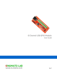
F1 Evaluation Platform for
Enhanced PIC® Microcontrollers
User’s Guide
2010 Microchip Technology Inc.
DS41401B
Note the following details of the code protection feature on Microchip devices:
•
Microchip products meet the specification contained in their particular Microchip Data Sheet.
•
Microchip believes that its family of products is one of the most secure families of its kind on the market today, when used in the
intended manner and under normal conditions.
•
There are dishonest and possibly illegal methods used to breach the code protection feature. All of these methods, to our
knowledge, require using the Microchip products in a manner outside the operating specifications contained in Microchip’s Data
Sheets. Most likely, the person doing so is engaged in theft of intellectual property.
•
Microchip is willing to work with the customer who is concerned about the integrity of their code.
•
Neither Microchip nor any other semiconductor manufacturer can guarantee the security of their code. Code protection does not
mean that we are guaranteeing the product as “unbreakable.”
Code protection is constantly evolving. We at Microchip are committed to continuously improving the code protection features of our
products. Attempts to break Microchip’s code protection feature may be a violation of the Digital Millennium Copyright Act. If such acts
allow unauthorized access to your software or other copyrighted work, you may have a right to sue for relief under that Act.
Information contained in this publication regarding device
applications and the like is provided only for your convenience
and may be superseded by updates. It is your responsibility to
ensure that your application meets with your specifications.
MICROCHIP MAKES NO REPRESENTATIONS OR
WARRANTIES OF ANY KIND WHETHER EXPRESS OR
IMPLIED, WRITTEN OR ORAL, STATUTORY OR
OTHERWISE, RELATED TO THE INFORMATION,
INCLUDING BUT NOT LIMITED TO ITS CONDITION,
QUALITY, PERFORMANCE, MERCHANTABILITY OR
FITNESS FOR PURPOSE. Microchip disclaims all liability
arising from this information and its use. Use of Microchip
devices in life support and/or safety applications is entirely at
the buyer’s risk, and the buyer agrees to defend, indemnify and
hold harmless Microchip from any and all damages, claims,
suits, or expenses resulting from such use. No licenses are
conveyed, implicitly or otherwise, under any Microchip
intellectual property rights.
Trademarks
The Microchip name and logo, the Microchip logo, dsPIC,
KEELOQ, KEELOQ logo, MPLAB, PIC, PICmicro, PICSTART,
PIC32 logo, rfPIC and UNI/O are registered trademarks of
Microchip Technology Incorporated in the U.S.A. and other
countries.
FilterLab, Hampshire, HI-TECH C, Linear Active Thermistor,
MXDEV, MXLAB, SEEVAL and The Embedded Control
Solutions Company are registered trademarks of Microchip
Technology Incorporated in the U.S.A.
Analog-for-the-Digital Age, Application Maestro, CodeGuard,
dsPICDEM, dsPICDEM.net, dsPICworks, dsSPEAK, ECAN,
ECONOMONITOR, FanSense, HI-TIDE, In-Circuit Serial
Programming, ICSP, Mindi, MiWi, MPASM, MPLAB Certified
logo, MPLIB, MPLINK, mTouch, Omniscient Code
Generation, PICC, PICC-18, PICDEM, PICDEM.net, PICkit,
PICtail, REAL ICE, rfLAB, Select Mode, Total Endurance,
TSHARC, UniWinDriver, WiperLock and ZENA are
trademarks of Microchip Technology Incorporated in the
U.S.A. and other countries.
SQTP is a service mark of Microchip Technology Incorporated
in the U.S.A.
All other trademarks mentioned herein are property of their
respective companies.
© 2010, Microchip Technology Incorporated, Printed in the
U.S.A., All Rights Reserved.
Printed on recycled paper.
ISBN: 978-1-60932-512-1
Microchip received ISO/TS-16949:2002 certification for its worldwide
headquarters, design and wafer fabrication facilities in Chandler and
Tempe, Arizona; Gresham, Oregon and design centers in California
and India. The Company’s quality system processes and procedures
are for its PIC® MCUs and dsPIC® DSCs, KEELOQ® code hopping
devices, Serial EEPROMs, microperipherals, nonvolatile memory and
analog products. In addition, Microchip’s quality system for the design
and manufacture of development systems is ISO 9001:2000 certified.
DS41401B-page 2
2010 Microchip Technology Inc.
F1 EVALUATION PLATFORM
USER’S GUIDE
Table of Contents
Preface ........................................................................................................................... 5
Chapter 1. F1 Evaluation Platform Overview
1.1 Introduction ................................................................................................... 11
1.2 Platform Contents ......................................................................................... 11
1.3 Hardware Features ....................................................................................... 11
Chapter 2. Getting Started
2.1 Introduction ................................................................................................... 13
2.2 Powering the F1 Evaluation Platform ........................................................... 13
2.3 Powering with PICkit™ 3 .............................................................................. 13
2.4 Powering with the Connector at JP3 ............................................................ 14
2.5 Powering with PICkit™ Serial ....................................................................... 14
2.6 Powering with the BLDC Expansion Header J3 ........................................... 15
2.7 Default Firmware .......................................................................................... 15
Chapter 3. Programming the F1 Evaluation Platform
3.1 Introduction ................................................................................................... 17
3.2 Programming/Development Tool Support .................................................... 17
3.3 Hardware Resources .................................................................................... 18
Chapter 4. Demo Code
4.1 Introduction ................................................................................................... 19
4.2 I2C™ Demo .................................................................................................. 19
4.3 LCD Demo .................................................................................................... 19
4.4 BLDC Demo ................................................................................................. 19
4.5 Combined Demo .......................................................................................... 19
Chapter 5. Hardware Libraries and Drivers
5.1 Introduction ................................................................................................... 21
5.2 I2C™ Driver .................................................................................................. 21
5.3 MCP9800 Driver ........................................................................................... 21
5.4 RTCC Driver ................................................................................................. 21
5.5 LCD Driver .................................................................................................... 21
5.6 Using the I2C™ Driver .................................................................................. 22
5.7 Using the LCD driver .................................................................................... 24
5.8 Using the RTCC Driver ................................................................................. 26
5.9 Using the MCP9800 Driver ........................................................................... 27
Chapter 6. Troubleshooting
6.1 Introduction ................................................................................................... 29
6.2 Common Problems ....................................................................................... 29
2010 Microchip Technology Inc.
DS41401B-page 3
F1 Evaluation Platform User’s Guide
Chapter 7. Schematics
7.1 Introduction .................................................................................................. 31
Index .............................................................................................................................39
Worldwide Sales and Service .....................................................................................42
DS41401B-page 4
2010 Microchip Technology Inc.
F1 EVALUATION PLATFORM
USER’S GUIDE
Preface
NOTICE TO CUSTOMERS
All documentation becomes dated, and this manual is no exception. Microchip tools and
documentation are constantly evolving to meet customer needs, so some actual dialogs
and/or tool descriptions may differ from those in this document. Please refer to our web site
(www.microchip.com) to obtain the latest documentation available.
Documents are identified with a “DS” number. This number is located on the bottom of each
page, in front of the page number. The numbering convention for the DS number is
“DSXXXXXA”, where “XXXXX” is the document number and “A” is the revision level of the
document.
For the most up-to-date information on development tools, see the MPLAB® IDE online help.
Select the Help menu, and then Topics to open a list of available online help files.
INTRODUCTION
This chapter contains general information that will be useful to know before using the
F1 Evaluation Platform User’s Guide. Items discussed in this chapter include:
•
•
•
•
•
•
•
•
Document Layout
Conventions Used in this Guide
Warranty Registration
Recommended Reading
The Microchip Web Site
Development Systems Customer Change Notification Service
Customer Support
Document Revision History
DOCUMENT LAYOUT
This document describes how to use the F1 Evaluation Platform User’s Guide as a
development tool to emulate and debug firmware on a target board. The manual layout
is as follows:
•
•
•
•
•
•
•
Chapter 1. “F1 Evaluation Platform Overview”
Chapter 2. “Getting Started”
Chapter 3. “Programming the F1 Evaluation Platform”
Chapter 4. “Demo Code”
Chapter 5. “Hardware Libraries and Drivers”
Chapter 6. “Troubleshooting”
Chapter 7. “Schematics”
2010 Microchip Technology Inc.
DS41401B-page 5
F1 Evaluation Platform User’s Guide
CONVENTIONS USED IN THIS GUIDE
This manual uses the following documentation conventions:
DOCUMENTATION CONVENTIONS
Description
Arial font:
Italic characters
Initial caps
Quotes
Underlined, italic text with
right angle bracket
Bold characters
N‘Rnnnn
Text in angle brackets < >
Courier New font:
Plain Courier New
Represents
Referenced books
Emphasized text
A window
A dialog
A menu selection
A field name in a window or
dialog
A menu path
MPLAB® IDE User’s Guide
...is the only compiler...
the Output window
the Settings dialog
select Enable Programmer
“Save project before build”
A dialog button
A tab
A number in verilog format,
where N is the total number of
digits, R is the radix and n is a
digit.
A key on the keyboard
Click OK
Click the Power tab
4‘b0010, 2‘hF1
Italic Courier New
Sample source code
Filenames
File paths
Keywords
Command-line options
Bit values
Constants
A variable argument
Square brackets [ ]
Optional arguments
Curly brackets and pipe
character: { | }
Ellipses...
Choice of mutually exclusive
arguments; an OR selection
Replaces repeated text
Represents code supplied by
user
DS41401B-page 6
Examples
File>Save
Press <Enter>, <F1>
#define START
autoexec.bat
c:\mcc18\h
_asm, _endasm, static
-Opa+, -Opa0, 1
0xFF, ‘A’
file.o, where file can be
any valid filename
mcc18 [options] file
[options]
errorlevel {0|1}
var_name [,
var_name...]
void main (void)
{ ...
}
2010 Microchip Technology Inc.
Preface
WARRANTY REGISTRATION
Please complete the enclosed Warranty Registration Card and mail it promptly.
Sending in the Warranty Registration Card entitles users to receive new product
updates. Interim software releases are available at the Microchip web site.
RECOMMENDED READING
This user’s guide describes how to use the F1 Evaluation Platform. Other useful documents are listed below. The following Microchip documents are available and recommended as supplemental reference resources.
Readme for F1 Evaluation Platform User’s Guide
For the latest information on using F1 Evaluation Platform User’s Guide, read the
“Readme for F1 Evaluation Platform User’s Guide.txt” file (an ASCII text
file) in the Readmes subdirectory of the MPLAB IDE installation directory. The Readme
file contains update information and known issues that may not be included in this
user’s guide.
Readme Files
For the latest information on using other tools, read the tool-specific Readme files in
the Readmes subdirectory of the MPLAB IDE installation directory. The Readme files
contain update information and known issues that may not be included in this user’s
guide.
2010 Microchip Technology Inc.
DS41401B-page 7
F1 Evaluation Platform User’s Guide
THE MICROCHIP WEB SITE
Microchip provides online support via our web site at www.microchip.com. This web
site is used as a means to make files and information easily available to customers.
Accessible by using your favorite Internet browser, the web site contains the following
information:
• Product Support – Data sheets and errata, application notes and sample
programs, design resources, user’s guides and hardware support documents,
latest software releases and archived software
• General Technical Support – Frequently Asked Questions (FAQs), technical
support requests, online discussion groups, Microchip consultant program
member listing
• Business of Microchip – Product selector and ordering guides, latest Microchip
press releases, listing of seminars and events, listings of Microchip sales offices,
distributors and factory representatives
DEVELOPMENT SYSTEMS CUSTOMER CHANGE NOTIFICATION SERVICE
Microchip’s customer notification service helps keep customers current on Microchip
products. Subscribers will receive e-mail notification whenever there are changes,
updates, revisions or errata related to a specified product family or development tool of
interest.
To register, access the Microchip web site at www.microchip.com, click on Customer
Change Notification and follow the registration instructions.
The Development Systems product group categories are:
• Compilers – The latest information on Microchip C compilers and other language
tools. These include the Hitech C16, MPLAB C18 and MPLAB C30 C compilers;
MPASM™ and MPLAB ASM30 assemblers; MPLINK™ and MPLAB LINK30
object linkers; and MPLIB™ and MPLAB LIB30 object librarians.
• In-Circuit Debuggers – The latest information on the Microchip in-circuit
debugger, MPLAB ICD 2, ICD3, PICkit™ 3.
• MPLAB® IDE – The latest information on Microchip MPLAB IDE, the Windows®
Integrated Development Environment for development systems tools. This list is
focused on the MPLAB IDE, MPLAB SIM simulator, MPLAB IDE Project Manager
and general editing and debugging features.
• Programmers – The latest information on Microchip programmers. These include
the MPLAB PM3 device programmers and PICkit™ 3 development programmers.
DS41401B-page 8
2010 Microchip Technology Inc.
Preface
CUSTOMER SUPPORT
Users of Microchip products can receive assistance through several channels:
•
•
•
•
Distributor or Representative
Local Sales Office
Field Application Engineer (FAE)
Technical Support
Customers should contact their distributor, representative or field application engineer
(FAE) for support. Local sales offices are also available to help customers. A listing of
sales offices and locations is included in the back of this document.
Technical support is available through the web site at: http://support.microchip.com
DOCUMENT REVISION HISTORY
Revision A (October 2009)
• Initial Release of this Document.
Revision B (September 2010)
• Revised Figures 7.1.4, 7.1.5 and 7.1.6
2010 Microchip Technology Inc.
DS41401B-page 9
F1 Evaluation Platform User’s Guide
NOTES:
DS41401B-page 10
2010 Microchip Technology Inc.
F1 EVALUATION PLATFORM
USER’S GUIDE
Chapter 1. F1 Evaluation Platform Overview
1.1
INTRODUCTION
Thank you for choosing the F1 Evaluation Platform. This kit allows you to begin
development using the PIC16LF1937 microcontroller (MCU).
The PIC16LF1937 is the first in a family of enhanced mid-range microcontrollers.
These architectural enhancements allow for more memory and faster computation than
that of legacy PIC16 microcontrollers.
The PIC16F1 and PIC12F1 family of microcontrollers are a series of 8-bit
microcontrollers derived from the popular PIC16 series of 8-bit PIC® microcontrollers.
The F1 derivatives feature an enhanced CPU, support for extended amounts of
memory, improved peripherals, and XLP low power. The F1 Evaluation Platform allows
you to evaluate these features for your application in a simple, low-cost platform.
This chapter introduces the F1 Evaluation Platform:
• Platform Contents
• Hardware Features
1.2
PLATFORM CONTENTS
The F1 Evaluation Platform contains the following items:
1. F1 Evaluation Platform Demo Board – www.microchip.com/F1Eval
1.3
HARDWARE FEATURES
The F1 Evaluation Platform has the following hardware features:
1.3.1
PIC16LF1937
The PIC16LF1937 is a 40-pin full-featured device, including:
1.
2.
3.
4.
5.
6.
7.
8.
9.
10.
11.
Enhanced PIC16 instruction set
8K Words of Flash memory
512 bytes of RAM
256 bytes of EEPROM
2 CCPs and 3 enhanced CCPs
MSSP (I2C™, SPI)
Enhanced USART
8- and 16-bit timers
32 MHz internal oscillator
Low-power 32 kHz crystal oscillator and
LCD controller.
1.3.2
MCP9800 I2C Temperature Sensor
The MCP9800 is a low-power, I2C temperature sensor with selectable 9 to 12 bits of
output resolution.
2010 Microchip Technology Inc.
DS41401B-page 11
F1 Evaluation Platform User’s Guide
1.3.3
PICkit™ 3 Programming/Debug Header
The PICkit 3 is a low-cost development tool that allows programming and debugging of
the PIC16LF1937 MCU using the PICkit ISCP™ header.
1.3.4
PICkit Serial Communications Header
The PICkit serial is a low-cost development tool that allows I2C, SPI and USART
protocols to be monitored and debugged through a simple 6-pin connector.
1.3.5
1 Button, 1 Potentiometer, 4 LEDs
Simple applications need the basic user interface elements. The button, potentiometer
and 1 LED are available for any application. The remaining 3 LEDs are shared with the
20-bit motor control expansion connector.
1.3.6
One 3.5 Digit LCD
The 3.5-digit LCD glass supplied on this board is a typical meter-type display with icons
for ohms, amps, etc. The PIC16LF1937 makes controlling the LCD very simple.
1.3.7
20-pin Motor Control Expansion Connector
This connector allows the PIC16LF1937 to control an optional Sensorless BLDC
add-on board (DM164130-2). The PIC16LF1937 has complete control of 3 phases so
other 1, 2, or 3-phase motor topologies can also be controlled.
1.3.8
Current Monitoring Connector
To demonstrate the Extreme Low Power (XLP) features of the PIC16LF1937, a
precision ammeter can be connected to the current monitoring connector. This allows
your application to be easily optimized for the lowest possible current.
1.3.9
Generous Prototyping Area
Our circuits are not your circuits. A prototyping area has been provided to extend the
functionality of this demo board to demonstrate the utility of the PIC16LF1937 in your
application.
DS41401B-page 12
2010 Microchip Technology Inc.
F1 EVALUATION PLATFORM
USER’S GUIDE
Chapter 2. Getting Started
2.1
INTRODUCTION
This chapter gives instruction to get your F1 Evaluation Platform powered up and
running the default demonstration. The following sections include:
•
•
•
•
•
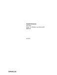
FIGURE 2-1:
2.2
Powering the F1 Evaluation Platform
Default Firmware
Programming the F1 Evaluation Platform with the PICkit™ 3
Attaching a PICkit Serial (optional)
Measuring the current consumption
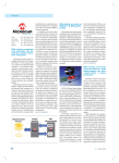
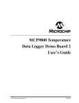
F1 EVALUATION PLATFORM (DM164130-1)
POWERING THE F1 EVALUATION PLATFORM
The PIC16LF1937 supplied with your F1 Evaluation Platform requires a supply voltage
of 1.8V-3.6V. Voltages above 3.6V will degrade or damage the device. There are four
ways to supply the necessary power.
1.
2.
3.
4.
2.3
Use PICkit 3,
Use the power connector at JP3,
Use PICkit Serial, or
Use the BLDC Expansion Header J3.
POWERING WITH PICkit™ 3
To power with the PICkit 3, perform the following steps:
1. Make sure a jumper or an ammeter is connected across JP2.
2. If you are using a BLDC expansion, remove the jumper at JP1.
2010 Microchip Technology Inc.
DS41401B-page 13
F1 Evaluation Platform User’s Guide
3. Configure the PICkit 3 to supply a voltage between 1.8 and 3.6V. For proper LCD
contrast, the supply should be 3.3V.
4. Attach the PICkit 3 to the PICkit ICSP™ connector at the end of the board.
5. Activate the PICkit 3 power output.
2.4
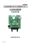
POWERING WITH THE CONNECTOR AT JP3
To power with the connector at JP3, perform the following steps:
1. Make sure a jumper or an ammeter is connected across JP2.
2. If you are using a BLDC expansion, remove the jumper at JP1.
3. Verify the supply voltage to be between 1.8 and 3.6V. For proper LCD contrast,
the supply should be 3.3V.
4. Attach the power supply to JP3.
5. Turn on the power supply.
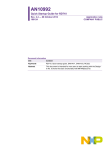
FIGURE 2-2:
2.5
POWERING WITH THE CONNECTOR AT JP3
POWERING WITH PICkit™ SERIAL
To power with the PICkit Serial, perform the following steps:
1. Make sure a jumper or an ammeter is connected across JP2.
2. If you are using a BLDC expansion, remove the jumper at JP1.
3. Configure the PICkit Serial to supply a voltage between 1.8 and 3.6V. For proper
LCD contrast, the supply should be 3.3V.
4. Attach the PICkit Serial to the PICkit Serial connector at the top corner of the
board.
5. Activate the PICkit Serial power output.
DS41401B-page 14
2010 Microchip Technology Inc.
Getting Started
2.6
POWERING WITH THE BLDC EXPANSION HEADER J3
The BLDC Expansion hardware contains a 3.3V linear regulator. This allows the 5-12V
motor power supply to power the PIC16LF1937. J3 pin 6 is the source for the 3.3V
power. To use this power perform the following steps.
1.
2.
3.
4.
5.
6.
2.7
Make sure a jumper or an ammeter is connected across JP2.
Insert the shorting jumper at JP1.
Verify that any attached PICkit 3 or PICkit serial is not supplying power.
Verify that there is NO power supply or shorting jumper at JP3.
Attach the BLDC expansion board.
Connect power to the BLDC expansion board.
DEFAULT FIRMWARE
The default firmware supplied with your F1 Evaluation Board Demo performs the
following functions:
1. Blink LEDs
2. Measure the ambient temperature
3. Run a BLDC motor (or try to if no motor is attached)
4. Display time/temperature/pot position/motor RPM on the LCD
5. User interface with a button and pot
For the latest firmware go to www.microchip.com/F1Eval
2.7.1
Blinking LEDs
The 4 LEDs indicate motor phase operation (D<2:4>) and the performance of the
primary state machine loop (D1).
2.7.2
Measuring the Ambient Temperature
The MCP9800 is polled when in Temperature Measurement mode. The measured
temperature is filtered, scaled to centigrade and displayed on the LCD.
2.7.3
BLDC Motor
One task of the demo code is to drive a BLDC motor attached to the BLDC Expansion
Header. The optional BLDC Controller board (DM164130-2) is required to drive the
motor. The code performs a series of forced commutation steps to attempt a sensorless
motor start. If no back EMF signal is detected, the code repeats the start-up sequence.
The LEDs blink at an increasing rate indicating the motor start attempts. If no motor
drive hardware is attached, this pattern can repeat or it may detect a BEMF signal in
the noise present on the BEMF sense inputs.
2010 Microchip Technology Inc.
DS41401B-page 15
F1 Evaluation Platform User’s Guide
2.7.4
LCD Display
The time, temperature, pot position and motor speed are displayed on the LCD. The
LCD is a 3.5-digit multimeter display with icons for amps, volts, ohms, etc. The display
uses 4 commons and 10 segment drives. The Timer1 oscillator is used to clock the
display peripheral and allow the LCD to display data even in Sleep. The LCD peripheral
was configured for a Type B waveform for this demo. This mode provides an interrupt
when the LCD can be updated. This interrupt is not required for Type A waveforms, but
the extra complexity of the interrupt allows the LCD peripheral to be used to provide the
real-time clock periodic interrupt. The different waveform types are described in section
21.9 of the PIC16LF193X data sheet (DS41364). Normally, the Timer1 counter would
be used, but this timer is required for the BLDC software. Because the LCD is clocked
from the 32.768 kHz crystal, the LCDIF operates at a multiple of the crystal frequency,
providing a very accurate time base for the real-time clock.
2.7.5
User Interface
Due to the extreme simplicity of this board, only a single button and a single pot are
available for user input. These two elements allow the user to cycle through the display
elements, change the motor speed and change the time.
Pressing and releasing the button cycles through the 4 display modes:
1. Time
2. Temperature
3. Pot ADC value
4. RPM
Turning the pot will change the motor speed or set the time.
If the display is showing the time, and the button is held down for 3 seconds, turning
the pot clockwise will increase the time, and counter clockwise will decrease the time.
Placing the pot in the center of the range will leave the time unchanged. A feature that
could be added as a simple programming exercise would be to allow the time change
to be faster or slower depending upon pot position.
DS41401B-page 16
2010 Microchip Technology Inc.
F1 EVALUATION PLATFORM
USER’S GUIDE
Chapter 3. Programming the F1 Evaluation Platform
3.1
INTRODUCTION
The F1 Evaluation Platform makes extensive use of the onboard peripherals of the
PIC16LF1937. This chapter provides guidance concerning the tools used for
programming the F1 evaluation board and a map of the board function to I/O pin and
pin function.
3.2
PROGRAMMING/DEVELOPMENT TOOL SUPPORT
The following development tools support the F1 Evaluation Platform:
1. PICkit™ 3
2. PICkit™ 2
3. REAL ICE™ in-circuit emulator (with adapter AC164110)
The PICkit™ tools can also power the F1 Evaluation Platform, therefore, no additional
hardware is required to get started. The ICSP™ pins of the PIC16LF1937 are
dedicated to the PICkit ICSP connector, eliminating interactions between the
Evaluation Platform and the programmer/debugger.
If you are developing with the REAL ICE emulator, you will need the AC164110 adaptor,
or the high-speed trace adaptor. These adaptors provide the inline 6 pin connector
required by the PICkit ICSP programming capability interface. You will also need a
power supply, please see Chapter 2. “Getting Started” for more on powering the F1
Evaluation Platform.
2010 Microchip Technology Inc.
DS41401B-page 17
F1 Evaluation Platform User’s Guide
3.3
HARDWARE RESOURCES
TABLE 3-1:
Pin Number
Pin Name
Pin Function Used
Board Function
1
RC7
EUSART RX
PICkit™ Serial Pin 1
2
RD4
Segment 17
LCD Pin 13, S1/S2/m/M
3
RD5
CCP1 Output B
BLDC pin 5, Phase U low drive
4
RD6
CCP1 Output C
BLDC pin 9, Phase V low drive
5
RD7
Segment 20
LCD pin 14, A/V/K/Omega
6
VSS
VSS
VSS
7
VDD
VDD
VDD
8
RB0
Segment 0
LCD pin 5, RC/BATT/-/AC
9
RB1
C12IN3-
BLDC pin 19, Phase V BEMF Zero Cross
10
RB2
AN8
Potentiometer
11
RB3
C12IN2-
BLDC pin 17, Phase U BEMF Zero Cross
14
RB4
COM1
LCD pin 1, Common 1
15
RB5
COM2
LCD pin 2, Common 2
16
RB6
PGC
PICkit 2 ICSP™ pin 5, PGC
17
RB7
PGD
PICkit 2 ICSP pin 4, PGD
18
MCLR
MCLR
PICkit ICSP Pin 1
19
RA0
Segment 12
LCD pin 11, 1A/1F/1E/1D
20
RA1
C12IN1-
BLDC pin 15, Phase W BEMF Zero Cross
21
RA2
COM3
LCD pin 3, Common 3
22
RA3
C1IN+
BLDC pin 16, BEMF Zero Cross Reference
23
RA4
Segment 4
LCD pin 8, 3B/3G/3C/3DP
24
RA5
Segment 5
LCD pin 9, 2A/2F/2E/2D
25
RE0
RE0
LED D4 and BLDC pin 3 Phase W high drive
26
RE1
RE1
LED D3 and BLDC pin 7 Phase U high drive
27
RE2
RE2
LED D2 and BLDC pin 11 Phase V high drive
28
VDD
VDD
VDD
29
VSS
VSS
VSS
30
RA7
Segment 2
LCD pin 7, 3A/3F/3E/3D
31
RA6
Segment 1
LCD pin 6, DH/RH/B-C/4DP
32
RC0
T1OSCO
32.768 kHz Crystal Drive
35
RC1
T1OSCI
32.768 kHz Crystal Drive
36
RC2
CCP1 Output A
BLDC pin 1, Phase W low drive
37
RC3
MSSP SCLK
MCP9800 SCLK and PICkit Serial pin 5
38
RD0
Common 4
LCD pin 4, Common 4
39
RD1
RD1
LED D1
40
RD2
RD2
Button Input
41
RD3
Segment 16
LCD pin 12, 1B/1G/1C/
42
RC4
MSSP SDA
MCP9800 SDA and PICkit Serial pin 4
43
RC5
Segment 10
LCD pin 10, 2B/2G/2C/2DP
44
RC6
EUSART TX
PICkit Serial pin 6
DS41401B-page 18
2010 Microchip Technology Inc.
F1 EVALUATION PLATFORM
USER’S GUIDE
Chapter 4. Demo Code
4.1
INTRODUCTION
The F1 Evaluation Platform demos are located at www.microchip.com/F1Eval. The
following demos are available:
1.
2.
3.
4.
I2C™ Demo
LCD Demo
BLDC Demo
Combined Demo
This chapter provides an overview to the functions provided by these demos.
4.2
I2C™ DEMO
The I2C demo reads the current temperature from the on-board MCP9800 I2C
temperature sensor. The I2C driver is used to extract the data. The resulting value is
converted to a PWM duty cycle and used to control the brightness of the LED D4. LED
D1 toggles at approximately 10 ms.
4.3
LCD DEMO
The LCD demo adds button, potentiometer, Real-Time Clock (RTC) and LCD support
to the I2C demo. The 32.768 kHz crystal is activated to maintain the Real-Time Clock
and to drive the LCD peripheral. An input driver is supplied to manage the button and
potentiometer. A state machine now controls the major features of the demo so that the
time, temperature and potentiometer value can be displayed on the LCD.
4.4
BLDC DEMO
The BLDC demo controls a sensorless, brushless DC motor connected to the PIC16F1
BLDC Expansion board (DM164130-2). Other motors can also be driven by making
appropriate modifications to the motor control parameters in the source code.
Refer to application note AN1305, “Sensorless 3-Phase Brushless Motor Control with
the PIC16FXXX” for detailed information regarding BLDC motor control.
4.5
COMBINED DEMO
The combined demo combines all the software from all the previous demos to show the
power of the PIC16LF1937. In this demo, the BLDC motor is seamlessly controlled
while displaying the time, temperature, potentiometer position or motor RPM/10. All
drivers are reused from the previous demos. The RTCC is driven from the LCD
peripheral.
The combined demo is preprogrammed in the F1 Evaluation Platform.
2010 Microchip Technology Inc.
DS41401B-page 19
F1 Evaluation Platform User’s Guide
NOTES:
DS41401B-page 20
2010 Microchip Technology Inc.
F1 EVALUATION PLATFORM
USER’S GUIDE
Chapter 5. Hardware Libraries and Drivers
5.1
INTRODUCTION
All of the demo code uses a common set of libraries to provide I2C, real-time clock,
MCP9800 and LCD services. These libraries may be useful for other applications so
they are documented here. These drivers are located at www.microchip.com/F1Eval.
5.2
I2C™ DRIVER
The I2C driver allows I2C requests to be queued and then handled either by interrupts
or by polling. The driver is configured during compilation to support polling or interrupts.
The I2C and LCD demos configure the driver for interrupt mode. The Combined demo
polls the I2C handler within the MCP9800 driver.
5.3
MCP9800 DRIVER
The MCP9800 driver uses the I2C driver to get the current temperature. The
mcp9800_get_temp function is fully blocking, so once a request is queued, the driver
polls the I2C subsystem until the data is complete. If the I2C driver is operating without
interrupts, the mcp9800_get_temp function repeatedly calls the I2C_handler
function to process all the I2C events. If the I2C driver is operating with interrupts, the
mcp9800_get_temp function simply inserts an I2C_TRANSACTION_T into the I2C
transaction queue and waits for the transaction to complete.
5.4
RTCC DRIVER
A software RTCC is managed by the supplied RTCC driver. This driver implements the
time() function required by the C compiler. Time is internally kept as seconds since
January 1, 1970. Standard C functions can be used to convert the time to the current
date. This driver has two modes. In the first mode, it expects to be called once per
second by the Timer1 interrupt. In the second mode, it expects to be called on every
LCD mode B frame. This allows the RTCC to keep accurate time even if Timer1 is
being used by some other function, such as the BLDC motor driver.
5.5
LCD DRIVER
The LCD driver contains the initialization code required for the LCD peripheral and the
mapping code required to control the 3.5-digit LCD supplied with this demo board. It is
a good starting point for the LCD driver your unique application will require.
2010 Microchip Technology Inc.
DS41401B-page 21
F1 Evaluation Platform User’s Guide
5.6
USING THE I2C™ DRIVER
The supplied software includes an I2C Master mode driver with the following features:
1.
2.
3.
4.
5.
6.
Interrupt driven or polled
Queued requests
Minimum memory requirements
Uses Restart to maximize bus bandwidth
Multiple atomic I2C transactions allowed at each queue entry
Completion flag for each queued block of I2C commands.
5.6.1
I2C Data Structures
Two data structures are defined to simplify interactions with the I2C driver.
5.6.1.1
I2C_RESULTS_T
The I2C_RESULTS_T is an enumerated type with the following enumerations:
TABLE 5-1:
I2C_RESULTS_T
I2C_REQUEST_PENDING
Request is in the queue or in process but it is not
done.
I2C_REQUEST_COMPLETE
The request is finished successfully.
I2C_REQUEST_STUCK_START
The request was aborted. The start condition did
not clear correctly.
I2C_REQUEST_ADDRESS_NO_ACK
The request was aborted. No ACK occurred on
the address, so the target device must not exist
or is not functioning.
I2C_REQUEST_DATA_NO_ACK
The request was aborted. Not all of the data
could be sent because the device did not ACK a
byte.
I2C_REQUEST_LOST_STATE
The I2C state machine had a RAM corruption
and the default case caught the failure. This will
infinite loop so you should never see it.
The data completion flag for an I2C request is of type I2C_RESULTS_T. This flag will
be I2C_REQUEST_PENDING until the request is complete. If the request completed
without errors, the value will be I2C_REQUEST_COMPLETE. If there were errors, the
value will reflect one of the other 4 error conditions.
5.6.1.2
I2C_T
The I2C_T is a structure representing one transaction on the I2C bus. A transaction
contains the following elements:
1. A 7- or 10-bit address. Address type is determined automatically by the driver.
R/W mode is implicit in the address and specified by bit 0.
2. An 8-bit baud rate. This is the value placed in SPADD. Predefined constants are
included that compute the SPADD value given an FOSC value. Set FOSC with
a #define before #including the I2C.h file.
3. A buffer_length. This is the number of bytes available for reading or writing
at the supplied data buffer.
4. A Buffer Pointer. Your application will allocate a block of memory for an I2C
transaction. Pass a pointer to this block via the Buffer Pointer. The block must
remain valid until the transaction is complete (i.e., if you allocate the block as a
non-static array within a function, you must not leave the function until the I2C
transaction is complete or the array may be reused by a different function).
DS41401B-page 22
2010 Microchip Technology Inc.
Hardware Libraries and Drivers
5.6.2
I2C Function Interface
5.6.2.1
i2c_init
The function i2c_init configures the I2C driver and makes it ready to receive
transaction in the transaction queue.
FIGURE 5-1:
initialize()
{
i2c_init(I2C_400K);
}
5.6.2.2
i2c_insert
The function i2c_insert places one complete set of Transaction Request Block
(TRB’s). TRBs can be bundled into an array of multiple TRBs and inserted as one large
request. The driver will ensure that all the TRBs in the list will be processed sequentially
with I2C restarts separating them.
FIGURE 5-2:
Send_data()
{
I2C_TRANSACTION_REQUEST_BLOCK trb_list[5];
I2C_RESULTS flag;
… populate the trb’s …
i2c_insert(5,trb_list, &flag);
}
5.6.2.3
i2c_build_write_trb / i2c_build_read_trb
The i2c_build_write_trb and i2c_build_read_trb functions are helpers to
assemble the I2C_TRANSACTION_REQUEST_BLOCKS from passed parameters.
FIGURE 5-3:
Send_one_byte()
{
I2C_TRANSACTION_REQUEST_BLOCK trb_list;
unsigned char data;
I2C_RESULTS flag;
data_block = .. my data byte ..
i2c_build_write_trb(&trb_list,ADDRESS, 1, &data, i2c_200K);
i2c_insert(1,&trb,&flag);
}
5.6.2.4
i2c_write_block / i2c_read_block
The i2c_write_block and i2c_read_block functions are helpers that assemble
a TRB, insert it into the queue and wait for the transaction to complete.
2010 Microchip Technology Inc.
DS41401B-page 23
F1 Evaluation Platform User’s Guide
FIGURE 5-4:
Send_one_byte()
{
unsigned char data;
i2c_write_block(ADDRESS, 1, &data, i2c_200K);
}
5.6.2.5
i2c_handler
The i2c_handler function must be called for each I2C state to be handled. This
function can be placed into the Interrupt Service Routine for your application or, you
can simply poll it often. If the i2c_write_block or i2c_read_block functions are
used when the driver is configured for polling, then this function will repeatedly be
called until the transaction completes.
FIGURE 5-5:
Interrupt_service_routine()
{
i2c_handler();
}
5.7
USING THE LCD DRIVER
The supplied LCD driver configures the LCD module for the I/O pins used by the F1
Evaluation Platform. Icon definitions are provided to simplify the software. A BCD to
7-segment display mapping function is also provided to further simplify control of the
LCD glass. For more information concerning the LCD peripheral, please consult the
LCD chapter in the PIC16LF1937 data sheet (DS41364).
5.7.1
LCD Data Structures
5.7.1.1
BCD_TYPE
To simplify BCD to the 7-segment display mapping, a BCD segment data type has been
provided. This data type is simply four 4-bit fields representing digits 0, 1, 2 and 3.
FIGURE 5-6:
typedef union
{
UINT16
val;
struct
{
unsigned
digit0 : 4;
unsigned
digit1 : 4;
unsigned
digit2 : 4;
unsigned
digit3 : 4;
};
} BCD_TYPE;
Simply place the number you want displayed in each digit position and call
lcd_display_digits. Digit 3 is the Most Significant ½ digit of the 3.5-digit LCD
glass. Therefore, the largest value displayable is 1FFF assuming hexidecimal digits or
1999 for decimal digits.
DS41401B-page 24
2010 Microchip Technology Inc.
Hardware Libraries and Drivers
5.7.2
LCD Function Interface
5.7.2.1
lcd_init
This function configures the LCD peripheral for this board and this glass. Type B
waveforms are used to allow the LCD peripheral to be used for the real-time clock
function. The Timer1 oscillator is configured as the LCD clock source.
FIGURE 5-7:
System_initialize()
{
lcd_init();
}
5.7.2.2
lcd_display_digits
This function accepts a BCD_TYPE variable and maps each digit to the correct
segments. Mapping the segments is done in two stages. First, the digit is converted to
the correct 7-segment mapping. Then, the 7-segment mapping is converted to the
actual glass segments with a long series of “if-else” statements. This function will need
extensive work in the “if-else” statements for applications driving different glass.
FIGURE 5-8:
void display_int(int t)
{
BCD_TYPE bcd;
bcd.digit0 = t %10;
t /= 10;
bcd.digit1 = t % 10;
t /= 10;
bcd.digit2 = t % 10;
t /= 10;
bcd.digit3 = t%10;
lcd_display_digits(bcd);
}
5.7.2.3
lcd_display_on / lcd_display_off
These two functions simply turn the LCD peripheral off. The Timer1 oscillator is left
running. One use for these functions is to implement display blinking.
FIGURE 5-9:
void update_blinking()
{
if(time(0) % 2) // if an odd number of seconds
{
lcd_display_on();
}
else
{
lcd_display_off();
}
}
2010 Microchip Technology Inc.
DS41401B-page 25
F1 Evaluation Platform User’s Guide
5.7.3
LCD Segment Definitions
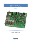
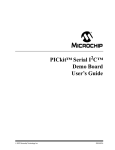
FIGURE 5-10:
LCD DISPLAY
There are many segments present on the F1 Evaluation Platform LCD. To access
these segments, simply set the supplied #defines to ‘1’ or ‘0’.
FIGURE 5-11:
void display_volts(int v)
{
display_int(v);
DP3 = 0;
DP2 = 0;
S1 = 0;
S2 = 0;
AMPS = 0;
VOLT = 1;
KILO = 0;
OHMS = 0;
if (v < 0)
MINUS = 1;
else
MINUS = 0;
}
5.8
USING THE RTCC DRIVER
The RTC driver simply keeps track of seconds. The power-up initial value is ‘0’,
however a function (rtcc_set) is provided to change that value. To keep the seconds
up-to-date, the function, rtcc_handler, must be called more frequently than the
defined value of CLOCKS_PER_SECOND. There are two options for the RTCC driver.
The first option is to use the Timer1 counter to provide a 1 Hz interrupt
(CLOCKS_PER_SECOND = 1). The second option is to use the LCD write-allowed
interrupt flag to provide a 128 Hz event (CLOCKS_PER_SECOND = 128). The two
choices are selected by defining use_lcdif or undefining use_lcdif.
5.8.1
RTCC Function Interface
5.8.1.1
rtcc_init
Intialize the RTCC function including Timer1, if required.
DS41401B-page 26
2010 Microchip Technology Inc.
Hardware Libraries and Drivers
FIGURE 5-12:
System_initialization()
{
rtcc_init();
}
5.8.1.2
rtcc_handler
The rtcc_handler function must be called frequently to keep the internal seconds
counter accurate.
FIGURE 5-13:
System_interrupt_service_routine()
{
If(TMR1IF & TMR1IE)
{
TMR1IF = 0;
rtcc_handler();
}
}
5.8.1.3
rtcc_set
After system initialization, the seconds counter is cleared to ‘0’. The standard C
libraries equate 0 seconds to Midnight, Jan 1, 1970. That time has expired a long time
ago, so a new time in seconds can be configured with rtcc_set().
FIGURE 5-14:
#include <time.h>
Time_set() // set the time & date to 1 second after midnight, July 4, 2009
{
struct tm time_str;
time_t unix_time;
time_str.tm_year = 2009; // the year
time_str.tm_mon = 7;
// the month
time_str.tm_mday = 4;
// the day of the month
time_str.tm_hour = 0;
// the hour (0-23)
time_str.tm_min = 0;
// the minutes
time_str.tm_sec = 1;
// the seconds
time_str.tm_isdst = -1; // daylight savings time modifier
unix_time = mktime(&time_str);
rtcc_set(unix_time);
}
5.8.1.4
time
The standard C libraries require the application to supply the time function. This
function returns the current time_t value or loads a supplied time_t value. The
interrupts are saved and restored to make this function safe for use with interrupt driven
code.
5.9
USING THE MCP9800 DRIVER
The MCP9800 is an I2C temperature sensor. The MCP9800 driver provides a simple
interface to the features in the sensor.
2010 Microchip Technology Inc.
DS41401B-page 27
F1 Evaluation Platform User’s Guide
5.9.1
MCP9800 Function Interface
5.9.1.1
mcp9800_init
This function configures the MCP9800 for 12-bit temperature, Continuous Conversion
mode. In this mode, the temperature is always ready to be read from the I2C interface.
FIGURE 5-15:
System_init()
{
i2c_init();
mcp9800_init();
}
5.9.1.2
mcp9800_get_temp
This function reads the current temperature and scales the result to degrees C * 10.
(24.3C is returned 243)
FIGURE 5-16:
Thermostat()
{
int temperature;
temperature = mcp9800_get_temp();
if(temperature > 260)
{
turn_on_air_conditioner();
}
}
DS41401B-page 28
2010 Microchip Technology Inc.
F1 EVALUATION PLATFORM
USER’S GUIDE
Chapter 6. Troubleshooting
6.1
INTRODUCTION
There may come a time when you need to determine why your F1 Evaluation Platform
is not performing correctly. This chapter lists a few of the problems that can prevent
proper operation.
6.2
COMMON PROBLEMS
6.2.1
The board will not power up
Make sure there is no shorting jumper at JP3. Then, go back and review Chapter
2. “Getting Started” of this manual.
6.2.2
LCD is blank, but everything else works
The demo code in supplied with the F1 Evaluation Platform uses the Timer1 oscillator
to drive the LCD. If the Timer1 oscillator is not oscillating, the LCD will remain blank.
Here are some steps to assure that the Timer1 oscillator is working properly.
1. Clean and dry the board especially around the components at the top right corner
of the PIC16LF1937.
2. Make sure no foreign material is shorting the crystal leads.
3. If you are using the RC0 and RC1 pins for some other function, you should
modify lcd_init to reconfigure the LCD peripheral for a different clock
source.
The Timer1 oscillator of the PIC16LF1937 is a very low-power design that can be easily
disrupted by stray leakage. In an actual application, Microchip recommends that the
crystal circuit be conformal coated to prevent leakage. Please review Application Note
AN1288, “Design Practices for Low-Power External Oscillators” for more information.
6.2.3
The motor spins, but then stops
The BLDC start-up algorithm could be having trouble finding the BEMF zero-crossing
signal required to synchronize the motor commutation.
If you have attached the BLDC add-on board and you are using the supplied BLDC
motor, then the pot labeled iRef needs to be turned completely counter clockwise to
assure that a good BEMF zero-crossing signal is detected by the PIC16LF1937.
If you are using a different motor, you need to adjust the zero-crossing threshold to
match the requirements of the motor. For more information, consult the documentation
supplied with the BLDC add-on board.
2010 Microchip Technology Inc.
DS41401B-page 29
F1 Evaluation Platform User’s Guide
NOTES:
DS41401B-page 30
2010 Microchip Technology Inc.
F1 EVALUATION PLATFORM
USER’S GUIDE
Chapter 7. Schematics
7.1
INTRODUCTION
To help understand the features of the F1 Evaluation Platform and the BLDC add-on
board, the schematics are included here.
2010 Microchip Technology Inc.
DS41401B-page 31
F1 Evaluation Platform User’s Guide
F1 Evaluation Platform Schematic (1 of 3)
7.1.1
DS41401B-page 32
2010 Microchip Technology Inc.
Schematics
7.1.2
F1 Evaluation Platform Schematic (2 of 3)
2010 Microchip Technology Inc.
DS41401B-page 33
F1 Evaluation Platform User’s Guide
7.1.3
F1 Evaluation Platform Schematic (3 of 3)
DS41401B-page 34
2010 Microchip Technology Inc.
Schematics
7.1.4
BLDC Add-On Schematic (1 of 3)
2010 Microchip Technology Inc.
DS41401B-page 35
F1 Evaluation Platform User’s Guide
7.1.5
BLDC Add-On Schematic (2 of 3)
DS41401B-page 36
2010 Microchip Technology Inc.
Schematics
7.1.6
BLDC Add-On Schematic (3 of 3)
2010 Microchip Technology Inc.
DS41401B-page 37
F1 Evaluation Platform User’s Guide
NOTES:
DS41401B-page 38
2010 Microchip Technology Inc.
F1 EVALUATION PLATFORM
USER’S GUIDE
Index
Numerics
I
2C Demo .................................................................. 19
3.5-digit LCD ............................................................ 12
ICSP pins ................................................................. 17
Internet Address......................................................... 8
A
L
AC164110 ................................................................ 17
Ammeter .................................................................. 14
LCD Demo ............................................................... 19
LCD Display ............................................................. 16
LCD Function Interface ............................................ 25
lcd_display_digits ................................... 25
lcd_display_on / lcd_display_off ..... 25
lcd_init......................................................... 25
Linear regulator ........................................................ 15
B
BEMF Zero crossing signal ...................................... 29
BLDC Demo ............................................................. 19
BLDC expansion ...................................................... 14
BLDC motor ............................................................. 15
C
C12IN3-.................................................................... 18
CCP1 Output A ........................................................ 18
CCP1 Output B ........................................................ 18
CCP1 Output C ........................................................ 18
Centigrade ............................................................... 15
COM1....................................................................... 18
COM2....................................................................... 18
COM3....................................................................... 18
Combined Demo ...................................................... 19
Common Problems .................................................. 29
Customer Notification Service.................................... 8
Customer Support ...................................................... 9
D
Documentation
Conventions ........................................................ 6
Layout ................................................................. 5
E
Enhanced midrange microcontrollers....................... 11
EUSART RX ............................................................ 18
F
F1 Evaluation Platform............................................. 11
F1 Evaluation Platform Schematic ........................... 32
H
Hardware Features .................................................. 11
16-bit timers ...................................................... 11
32-MHz internal oscillator ................................. 11
CCPs ................................................................ 11
EEPROM .......................................................... 11
Enhanced USART ............................................ 11
LCD controller ................................................... 11
RAM .................................................................. 11
Hardware Libraries & Drivers ................................... 21
2010 Microchip Technology Inc.
M
MCLR ....................................................................... 18
MCP9800 ................................................................. 11
Temperature sensor.......................................... 11
Microchip Internet Web Site ....................................... 8
MSSP SCLK............................................................. 18
MSSP SDA............................................................... 18
P
PGC ......................................................................... 18
PGD ......................................................................... 18
PIC® microcontrollers............................................... 11
PIC16 series............................................................. 11
PIC16F1 Evaluation Kit ............................................ 11
PIC16F1 family......................................................... 11
PIC16LF1937 ........................................................... 11
PICkit ICSP™ programming capability interface...... 17
PICkit Serial ............................................................. 14
PICkit Serial connector............................................. 14
PICkit Serial power output........................................ 14
PICkit™ 2 ................................................................. 17
PICkit™ 3 ................................................................. 17
Platform Contents .................................................... 11
F1 Evaluation Platform Demo Board ................ 11
Powering with PICkit 3 ............................................. 13
JP1.................................................................... 13
JP2.................................................................... 13
PICkit ICSP connector ...................................... 14
Voltage.............................................................. 14
Programming and debugging................................... 12
DS41401B-page 39
F1 Evaluation Platform User’s Guide
R
RD1 .......................................................................... 18
RD2 .......................................................................... 18
RE0 .......................................................................... 18
RE1 .......................................................................... 18
RE2 .......................................................................... 18
Reading, Recommended............................................ 7
Readme...................................................................... 7
REAL ICE™ in-circuit emulator ................................ 17
S
Segment 17 .............................................................. 18
Sensorless BLCD add-on board............................... 12
Supply voltage.......................................................... 13
T
T1OSCI .................................................................... 18
T1OSCO .................................................................. 18
U
User Interface........................................................... 16
Pot ADC value .................................................. 16
RPM .................................................................. 16
Temperature ..................................................... 16
Time .................................................................. 16
W
Warranty Registration................................................. 7
WWW Address ........................................................... 8
X
XLP low power ......................................................... 11
DS41401B-page 40
2010 Microchip Technology Inc.
F1 Evaluation Platform User’s Guide
NOTES:
2010 Microchip Technology Inc.
DS41401B-page 41
Worldwide Sales and Service
AMERICAS
ASIA/PACIFIC
ASIA/PACIFIC
EUROPE
Corporate Office
2355 West Chandler Blvd.
Chandler, AZ 85224-6199
Tel: 480-792-7200
Fax: 480-792-7277
Technical Support:
http://support.microchip.com
Web Address:
www.microchip.com
Asia Pacific Office
Suites 3707-14, 37th Floor
Tower 6, The Gateway
Harbour City, Kowloon
Hong Kong
Tel: 852-2401-1200
Fax: 852-2401-3431
India - Bangalore
Tel: 91-80-3090-4444
Fax: 91-80-3090-4123
India - New Delhi
Tel: 91-11-4160-8631
Fax: 91-11-4160-8632
Austria - Wels
Tel: 43-7242-2244-39
Fax: 43-7242-2244-393
Denmark - Copenhagen
Tel: 45-4450-2828
Fax: 45-4485-2829
India - Pune
Tel: 91-20-2566-1512
Fax: 91-20-2566-1513
France - Paris
Tel: 33-1-69-53-63-20
Fax: 33-1-69-30-90-79
Japan - Yokohama
Tel: 81-45-471- 6166
Fax: 81-45-471-6122
Germany - Munich
Tel: 49-89-627-144-0
Fax: 49-89-627-144-44
Atlanta
Duluth, GA
Tel: 678-957-9614
Fax: 678-957-1455
Boston
Westborough, MA
Tel: 774-760-0087
Fax: 774-760-0088
Chicago
Itasca, IL
Tel: 630-285-0071
Fax: 630-285-0075
Cleveland
Independence, OH
Tel: 216-447-0464
Fax: 216-447-0643
Dallas
Addison, TX
Tel: 972-818-7423
Fax: 972-818-2924
Detroit
Farmington Hills, MI
Tel: 248-538-2250
Fax: 248-538-2260
Kokomo
Kokomo, IN
Tel: 765-864-8360
Fax: 765-864-8387
Los Angeles
Mission Viejo, CA
Tel: 949-462-9523
Fax: 949-462-9608
Santa Clara
Santa Clara, CA
Tel: 408-961-6444
Fax: 408-961-6445
Toronto
Mississauga, Ontario,
Canada
Tel: 905-673-0699
Fax: 905-673-6509
Australia - Sydney
Tel: 61-2-9868-6733
Fax: 61-2-9868-6755
China - Beijing
Tel: 86-10-8528-2100
Fax: 86-10-8528-2104
China - Chengdu
Tel: 86-28-8665-5511
Fax: 86-28-8665-7889
Korea - Daegu
Tel: 82-53-744-4301
Fax: 82-53-744-4302
China - Chongqing
Tel: 86-23-8980-9588
Fax: 86-23-8980-9500
Korea - Seoul
Tel: 82-2-554-7200
Fax: 82-2-558-5932 or
82-2-558-5934
China - Hong Kong SAR
Tel: 852-2401-1200
Fax: 852-2401-3431
Malaysia - Kuala Lumpur
Tel: 60-3-6201-9857
Fax: 60-3-6201-9859
China - Nanjing
Tel: 86-25-8473-2460
Fax: 86-25-8473-2470
Malaysia - Penang
Tel: 60-4-227-8870
Fax: 60-4-227-4068
China - Qingdao
Tel: 86-532-8502-7355
Fax: 86-532-8502-7205
Philippines - Manila
Tel: 63-2-634-9065
Fax: 63-2-634-9069
China - Shanghai
Tel: 86-21-5407-5533
Fax: 86-21-5407-5066
Singapore
Tel: 65-6334-8870
Fax: 65-6334-8850
China - Shenyang
Tel: 86-24-2334-2829
Fax: 86-24-2334-2393
Taiwan - Hsin Chu
Tel: 886-3-6578-300
Fax: 886-3-6578-370
China - Shenzhen
Tel: 86-755-8203-2660
Fax: 86-755-8203-1760
Taiwan - Kaohsiung
Tel: 886-7-213-7830
Fax: 886-7-330-9305
China - Wuhan
Tel: 86-27-5980-5300
Fax: 86-27-5980-5118
Taiwan - Taipei
Tel: 886-2-2500-6610
Fax: 886-2-2508-0102
China - Xian
Tel: 86-29-8833-7252
Fax: 86-29-8833-7256
Thailand - Bangkok
Tel: 66-2-694-1351
Fax: 66-2-694-1350
Italy - Milan
Tel: 39-0331-742611
Fax: 39-0331-466781
Netherlands - Drunen
Tel: 31-416-690399
Fax: 31-416-690340
Spain - Madrid
Tel: 34-91-708-08-90
Fax: 34-91-708-08-91
UK - Wokingham
Tel: 44-118-921-5869
Fax: 44-118-921-5820
China - Xiamen
Tel: 86-592-2388138
Fax: 86-592-2388130
China - Zhuhai
Tel: 86-756-3210040
Fax: 86-756-3210049
08/04/10
DS41401B-page 42
2010 Microchip Technology Inc.