1
User’s Manual
LG Programmable Logic Controller
Positioning Module(Pulse-Out Type)
GLOFA
MASTER-K
G3F-POPA
G4F-POPA
G4F-POPB
G6F-POPA
LG Industrial System
Caution for safety
Please read the safety information described in the data sheet and this manual carefully prior to using the
product.
Caution items described here are only for G3F-POPA, G4F-POPA, G4F-POPB and G6F-POPA .
Please refer to GLOFA CPU module or MASTER-K CPU module-related user manual respectively according
to CPU module used for the details on safety information for PLC system.
Cautions are intended to remind you of precautions in the warning triangle as displayed below as based on
the Danger level.
!
!
!
Warning
Death, fatal wound or considerable property loss could happen if
appropriate precautions are not taken.
Caution
Serious or slight injury or property loss could happen by dangerous
situations if appropriate treatment is not taken.
Caution may describe serious results according to situations.
Be sure to observe the 2 displays where important information is specified.
Keep the user manual nearby for prompt reference as necessary.
Designing Caution
!
Caution
8 Don’t let input/output signal line connected with the driver and sensor be
wired close to high-voltage or power cable but min. 100mm away
if possible, in order to prevent abnormal operation caused by noise.
Installing Caution
!
Wiring Caution
!
Caution
-Use PLC in conditions as described
-Connection distance between
in the general specification.
position- decision module and driver
-If not, electric shock, fire, abnormal
.
Caution
shall be as short as possible (1 –3 m)
operation or damage on product may
-Length of the connection cable
occur.
shall be as short as possible
-Besure to fix the module after inserting
-Use safe power source(DC 5V, DC24V)
the mounting protrusion into the module
-If any noise is expected, let input/output
mounting hole
signal line wired in twist pair and shield
-Abnormal operation, error or dropping
cable
may happen if the module is not
equipped correctly.
Caution for preparation, repair
!
!
Warning
Caution
-Don’t touch the terminal when powered,
-Don’t remove PCB from the module
abnormal operation may happen.
case nor remodel the module.
-Prior to cleaning or tightening the
error, abnormal operation, damage on
the terminal screws, let it powered off.
product may happen.
-If not, error or abnormal operation
Assembly/disassembly of the module
may happen.
shall be after powered off
-If not, error or abnormal operation
may happen.
Caution for waste
!
Caution
4 Product waste shall be processed as industrial waste .
◎ CONTENTS ◎
Chapter 1 Introduction
⋯ ⋯ ⋯ ⋯ ⋯ ⋯ ⋯ ⋯ ⋯ ⋯ ⋯ ⋯ ⋯ ⋯ ⋯ ⋯ ⋯ ⋯ ⋯ ⋯ 1-1 ~ 1-13
1.1 Features ⋯⋯⋯⋯⋯⋯⋯⋯⋯⋯⋯⋯⋯⋯⋯⋯⋯⋯⋯⋯⋯⋯⋯⋯⋯⋯1 - 2
1.2 Features Of Position-Decision Control Function ⋯⋯⋯⋯⋯⋯⋯⋯ 1 - 3
1.2.1 Position-Decision Control Function ⋯⋯⋯⋯⋯⋯⋯⋯⋯⋯⋯⋯⋯⋯⋯
⋯⋯⋯⋯⋯⋯⋯⋯⋯⋯⋯⋯⋯⋯⋯⋯1 - 6
1.2.2 Introduction Of The Operation Mode
1.2.3 Introduction Of Acceleration/Deceleration Processing
1.2. 4 Introduction Of Starting
1 - 3
⋯⋯⋯⋯⋯⋯⋯⋯⋯
1 - 11
⋯⋯⋯⋯⋯⋯⋯⋯⋯⋯⋯⋯⋯⋯⋯⋯⋯⋯ 1- 12
1.2. 5 Introduction Of The Return To Starting Point
⋯⋯⋯⋯⋯⋯⋯⋯⋯⋯⋯⋯⋯ 1 13
Chapte r 2 Specification ⋯ ⋯ ⋯ ⋯ ⋯ ⋯ ⋯ ⋯ ⋯ ⋯ ⋯ ⋯ ⋯ ⋯ ⋯ ⋯ ⋯ ⋯ ⋯ ⋯ ⋯ 2-1 ~ 2-12
2.1 General Specification⋯⋯⋯⋯⋯⋯⋯⋯⋯⋯⋯⋯⋯⋯⋯⋯⋯⋯⋯⋯⋯⋯ 2 - 1
2.2 Performance Specification ⋯⋯⋯⋯⋯⋯⋯⋯⋯⋯⋯⋯⋯⋯⋯⋯⋯⋯⋯ 2 - 3
2.3 Input/Output Specification Of The Outer Interface ⋯⋯⋯⋯⋯⋯⋯ 2 - 4
2.3.1 Input Speci fication
⋯⋯⋯⋯⋯⋯⋯⋯⋯⋯⋯⋯⋯⋯⋯⋯⋯⋯⋯⋯⋯ 2 - 4
2.3.2 Output Specification
⋯⋯⋯⋯⋯⋯⋯⋯⋯⋯⋯⋯⋯⋯⋯⋯⋯⋯⋯⋯⋯ 2 - 5
2.4 Outer Interface Connector⋯⋯⋯⋯⋯⋯⋯⋯⋯⋯⋯⋯⋯⋯⋯⋯⋯ 2 - 6
2.4.1 Connector’s Pin Arrangement⋯⋯⋯⋯⋯⋯⋯⋯⋯⋯⋯⋯⋯⋯⋯⋯⋯
2.4.2 Inner Circuit
2 - 6
⋯⋯⋯⋯⋯⋯⋯⋯⋯⋯⋯⋯⋯⋯⋯⋯⋯⋯⋯⋯⋯⋯⋯ 2 - 8
2.5 Designation And Function Of The Parts⋯⋯⋯⋯⋯⋯⋯⋯ 2 - 11
2.6 Connector’s Pin Arrangement
⋯⋯⋯⋯⋯⋯⋯⋯⋯⋯⋯⋯⋯⋯⋯ 2 - 12
Chapter 3 Functions ⋯ ⋯ ⋯ ⋯ ⋯ ⋯ ⋯ ⋯ ⋯ ⋯ ⋯ ⋯ ⋯ ⋯ ⋯ ⋯ ⋯ ⋯ ⋯ ⋯ ⋯ 3-1 ~ 3-46
3.1 Position-Decision Control
⋯⋯⋯⋯⋯⋯⋯⋯⋯⋯⋯⋯⋯⋯⋯⋯⋯⋯ 3 - 1
3.1.1 Position Control
⋯⋯⋯⋯⋯⋯⋯⋯⋯⋯⋯⋯⋯⋯⋯⋯⋯⋯⋯⋯ 3 - 1
3.1.2 Speed Control
⋯⋯⋯⋯⋯⋯⋯⋯⋯⋯⋯⋯⋯⋯⋯⋯⋯⋯⋯⋯ 3 - 7
3.1.3 Speed/Position Switchover Control
⋯⋯⋯⋯⋯⋯⋯⋯⋯⋯⋯⋯⋯ 3 - 9
3.2 Operation Mode⋯⋯⋯⋯⋯⋯⋯⋯⋯⋯⋯⋯⋯⋯⋯⋯⋯⋯⋯⋯⋯⋯⋯ 3 - 10
3.2.1 Separate Operation
⋯⋯⋯⋯⋯⋯⋯⋯⋯⋯⋯⋯⋯⋯⋯⋯⋯⋯⋯ 3 - 11
◎ CONTENTS ◎
⋯⋯⋯⋯⋯⋯⋯⋯⋯⋯⋯⋯⋯⋯⋯⋯⋯⋯⋯⋯⋯3 - 13
3.2.2 Repeated Operation
3 - 16
3.2. 3 Auto-Operation⋯⋯⋯⋯⋯⋯⋯⋯⋯⋯⋯⋯⋯⋯⋯⋯⋯⋯⋯⋯⋯⋯⋯
3.2. 4 Continuous Operation
3.2. 5 Constant Operation
⋯⋯⋯⋯⋯⋯⋯⋯⋯⋯⋯⋯⋯⋯⋯⋯⋯⋯⋯⋯ 3 - 17
⋯⋯⋯⋯⋯⋯⋯⋯⋯⋯⋯⋯⋯⋯⋯⋯⋯⋯⋯⋯⋯ 3 - 18
3.2. 6 Position-Decision Constant Operation
⋯⋯⋯⋯⋯⋯⋯⋯⋯⋯⋯⋯⋯⋯⋯ 3 - 20
3.3 Position -Decision Stop [ P O S ζ_ S T P ] ⋯⋯⋯⋯⋯⋯⋯⋯⋯⋯⋯⋯⋯⋯ 3 - 21
3. 3.1 Stop Command And Stop Causes ⋯⋯⋯⋯⋯⋯⋯⋯⋯⋯⋯⋯⋯⋯⋯⋯
3 - 21
3. 3.2 Stop Processing And Priority ⋯⋯⋯⋯⋯⋯⋯⋯⋯⋯⋯⋯⋯⋯⋯⋯⋯⋯
3 - 22
3.4 Restart After Position -Decision Stop
3.5 Return To Starting Point
[ P O S ζ_ O R G ]
[PO S ζ_AST]
⋯⋯⋯⋯⋯⋯⋯⋯⋯ 3 - 23
⋯⋯⋯⋯⋯⋯⋯⋯⋯⋯⋯⋯⋯⋯⋯ 3 - 23
3. 5.1 How To Return To Starting Point⋯⋯⋯⋯⋯⋯⋯⋯⋯⋯⋯⋯⋯⋯⋯⋯⋯
3. 5. 2 Starting Point Detection After Approximate Starting Point Off
⋯⋯⋯⋯⋯⋯ 3 - 24
3. 5. 3 Starting Point Detection After Deceleration At Approximate Starting Point On
3. 5. 4 Starting Point And Starting Point Detection By Top/Bottom Limit
3. 5. 5 Starting Point Detection By Approximate Starting Point
3 - 23
⋯3 - 26
⋯⋯ 3 - 27
⋯⋯⋯⋯⋯⋯ 3 - 28
3.6 Manual Operation⋯⋯⋯⋯⋯⋯⋯⋯⋯⋯⋯⋯⋯⋯⋯⋯⋯⋯⋯⋯⋯⋯⋯ 3 - 29
3. 6.1 Jog Operation[ P O Sζ_JOG]
⋯⋯⋯⋯⋯⋯⋯⋯⋯⋯⋯⋯⋯⋯⋯⋯⋯⋯ 3 - 29
3. 6. 2 Operation Of Manual Pulse Generator [ P O S ζ_MPG]
3. 6. 3 Inching Operation[ P O S ζ_INC]
⋯⋯⋯⋯⋯⋯⋯⋯⋯⋯ 3 - 31
⋯⋯⋯⋯⋯⋯⋯⋯⋯⋯⋯⋯⋯⋯⋯⋯ 3 - 32
3. 6. 4 Shift To Prior Position To Manual Operation [ P O S ζ_RPT]
3.7 Speed Change In Position-Decision Operation
3. 7.1 Speed Change Command[ P O Sζ_VCG]
⋯⋯⋯⋯⋯⋯⋯ 3 - 33
⋯⋯⋯⋯⋯⋯⋯⋯ 3 - 34
⋯⋯⋯⋯⋯⋯⋯⋯⋯⋯⋯⋯⋯⋯ 3 - 34
3. 7. 2 Operation Step No. Change By Continuous Operation [ P O Sζ_ N M ]
3. 7. 3 Speed Change By Speed Override [ P O S ζ_ O R ]
⋯⋯⋯ 3 - 35
⋯⋯⋯⋯⋯⋯⋯⋯ 3 - 37
3.8 Top/Bottom Stroke Limit⋯⋯⋯⋯⋯⋯⋯⋯⋯⋯⋯⋯⋯⋯⋯⋯ 3 - 39
3. 8.1 Outer Input Top/Bottom Stroke Limit
3. 8. 2 S/W Top/Bottom Stroke Limit
⋯⋯⋯⋯⋯⋯⋯⋯⋯⋯⋯⋯⋯⋯ 3 - 39
⋯⋯⋯⋯⋯⋯⋯⋯⋯⋯⋯⋯⋯⋯⋯⋯⋯ 3 - 40
3.9 Random-Positioned Address Value Setting To Starting Point And Present Position Change 3 - 41
3. 9.1 Random-Positioned Address Value Setting To Starting Point⋯⋯⋯⋯⋯⋯⋯
3 - 41
◎ CONTENTS ◎
3. 9. 2 Present Position Change [ P O S ζ _PRE]
⋯⋯⋯⋯⋯⋯⋯⋯⋯⋯⋯⋯⋯⋯ 3 - 41
3.10 Fixed Starting Point Setting[ P O Sζ_FLT] ⋯⋯⋯⋯⋯⋯⋯⋯⋯⋯⋯⋯ 3 - 42
3.11 Teaching Function ⋯⋯⋯⋯⋯⋯⋯⋯⋯⋯⋯⋯⋯⋯⋯⋯⋯⋯⋯⋯⋯ 3 - 42
3. 11.1 RAM Teaching Function And ROM Teaching Function
3. 11. 2 Speed Teaching [ P O Sζ_VLT]
3. 12. 3 Position Teaching [ P O S ζ_TEA]
⋯⋯⋯⋯⋯⋯⋯⋯ 3 - 42
⋯⋯⋯⋯⋯⋯⋯⋯⋯⋯⋯⋯⋯⋯⋯⋯ 3 - 43
⋯⋯⋯⋯⋯⋯⋯⋯⋯⋯⋯⋯⋯⋯⋯⋯⋯ 3 - 44
3.12 Operation Step No.Assignment[ P O S ζ_ S M C ] ⋯⋯⋯⋯⋯⋯⋯⋯⋯⋯ 3 - 45
3.13 Parameter Change In Program에 서
3 - 46
[ P O S ζ_ P R M ] ⋯⋯⋯⋯⋯⋯⋯⋯⋯
C h a p t e r 4 S / W P a c k a g e ⋯ ⋯ ⋯ ⋯ ⋯ ⋯ ⋯ ⋯ ⋯ ⋯ ⋯ ⋯ ⋯ ⋯ ⋯ 4 - 1 ~ 4 -5
4.1 Main Menu Bar ⋯⋯⋯⋯⋯⋯⋯⋯⋯⋯⋯⋯⋯⋯⋯⋯⋯⋯⋯⋯⋯⋯⋯ 4 - 2
4.2 Shortened Icon ⋯⋯⋯⋯⋯⋯⋯⋯⋯⋯⋯⋯⋯⋯⋯⋯⋯⋯⋯⋯⋯⋯⋯ 4 - 4
4.3 Pre-Operation Mode ⋯⋯⋯⋯⋯⋯⋯⋯⋯⋯⋯⋯⋯⋯⋯⋯⋯⋯⋯⋯ 4 - 4
4. 3.1 Monitoring Axis Selection⋯⋯⋯⋯⋯⋯⋯⋯⋯⋯⋯⋯⋯⋯⋯⋯⋯
4 - 4
4 . 3. 2 M o n i t o r i n g S t a r t / S t o p ⋯⋯⋯⋯⋯⋯⋯⋯⋯⋯⋯⋯⋯⋯⋯⋯ ⋯
4 - 4
4. 3. 3 Command Selection_ Selection Of The Axis To Pre-Operate⋯⋯⋯⋯⋯⋯⋯
4 - 4
4 . 3 . 4 P r e- O p e r a t i o n B y S / W P a c k a g e
4. 3. 5 Jog Operation
By
S/W Pac kage
⋯ ⋯⋯ ⋯⋯⋯⋯⋯⋯⋯⋯ ⋯ 4 - 5
⋯⋯⋯⋯⋯⋯⋯⋯⋯⋯⋯⋯⋯⋯⋯⋯ 4 - 5
Chapter 5 Position- Decision Parameters ⋯ ⋯ ⋯ ⋯ ⋯ ⋯ ⋯ ⋯ ⋯ ⋯ ⋯ ⋯ 5 -1 ~ 5- 17
5.1 Basic Parameters ⋯⋯⋯⋯⋯⋯⋯⋯⋯⋯⋯⋯⋯⋯⋯⋯⋯⋯⋯ 5 - 3
5. 1.1 Acceleration/Deceleration Time⋯⋯⋯⋯⋯⋯⋯⋯⋯⋯⋯⋯⋯⋯⋯⋯⋯⋯
5 - 3
5. 1. 2 Backlash Correction ⋯⋯⋯⋯⋯⋯⋯⋯⋯⋯⋯⋯⋯⋯⋯⋯⋯⋯⋯⋯⋯⋯5
- 4
5. 1. 3 Bias Speed ⋯⋯⋯⋯⋯⋯⋯⋯⋯⋯⋯⋯⋯⋯⋯⋯⋯⋯⋯⋯⋯⋯⋯⋯
5 - 5
5. 1. 4 S/W Top/Bottom Stroke Limit⋯⋯⋯⋯⋯⋯⋯⋯⋯⋯⋯⋯⋯⋯⋯⋯⋯⋯⋯
5- 6
5. 1. 5 Speed Limits ⋯⋯⋯⋯⋯⋯⋯⋯⋯⋯⋯⋯⋯⋯⋯⋯⋯⋯⋯⋯⋯⋯⋯⋯
5- 6
5. 1. 6 Position Passing Time ⋯⋯⋯⋯⋯⋯⋯⋯⋯⋯⋯⋯⋯⋯⋯⋯⋯⋯⋯⋯⋯
5 -6
5.2 Output Direction ⋯⋯⋯⋯⋯⋯⋯⋯⋯⋯⋯⋯⋯⋯⋯⋯⋯⋯⋯⋯⋯⋯⋯ 5 - 8
5.3 Rotation Direction ⋯⋯⋯⋯⋯⋯⋯⋯⋯⋯⋯⋯⋯⋯⋯⋯⋯⋯⋯⋯⋯
5 -8
5.4 M Code Mode ⋯⋯⋯⋯⋯⋯⋯⋯⋯⋯⋯⋯⋯⋯⋯⋯⋯⋯⋯⋯⋯⋯⋯⋯ 5 - 9
◎ CONTENTS ◎
5.5 Jog Speed ⋯⋯⋯⋯⋯⋯⋯⋯⋯⋯⋯⋯⋯⋯⋯⋯⋯⋯⋯⋯⋯⋯⋯⋯⋯ 5 - 13
5.6 Processing Method Of The Return To Starting Point⋯⋯⋯⋯⋯⋯⋯⋯ 5 - 13
5.7 Return To Starting Point⋯⋯⋯⋯⋯⋯⋯⋯⋯⋯⋯⋯⋯⋯⋯⋯⋯⋯⋯ 5 - 14
5. 7.1 Direction⋯⋯⋯⋯⋯⋯⋯⋯⋯⋯⋯⋯⋯⋯⋯⋯⋯⋯⋯⋯⋯⋯⋯⋯
5 - 14
5. 7. 2 Correction⋯⋯⋯⋯⋯⋯⋯⋯⋯⋯⋯⋯⋯⋯⋯⋯⋯⋯⋯⋯⋯⋯⋯⋯
5 - 14
5. 7. 3 Speed Of The Return To Starting Point
⋯⋯⋯⋯⋯⋯⋯⋯⋯⋯⋯⋯⋯⋯⋯ 5 - 15
5. 7. 4 Address⋯⋯⋯⋯⋯⋯⋯⋯⋯⋯⋯⋯⋯⋯⋯⋯⋯⋯⋯⋯⋯⋯⋯⋯⋯
5 - 15
5. 7. 5 Dwell Time⋯⋯⋯⋯⋯⋯⋯⋯⋯⋯⋯⋯⋯⋯⋯⋯⋯⋯⋯⋯⋯⋯⋯⋯
5 - 15
5.8 Zone Setting ⋯⋯⋯⋯⋯⋯⋯⋯⋯⋯⋯⋯⋯⋯⋯⋯⋯⋯⋯⋯⋯⋯ 5 - 16
Chapter 6 Position Data For Position Decision ⋯ ⋯ ⋯ ⋯ ⋯ ⋯ ⋯ ⋯ ⋯ ⋯ ⋯ 6-1 ~ 6-7
6.1 Step No.⋯⋯⋯⋯⋯⋯⋯⋯⋯⋯⋯⋯⋯⋯⋯⋯⋯⋯⋯⋯⋯⋯⋯⋯⋯⋯ 6 - 3
6.2 Coordinates ⋯⋯⋯⋯⋯⋯⋯⋯⋯⋯⋯⋯⋯⋯⋯⋯⋯⋯⋯⋯⋯⋯⋯⋯⋯6 - 3
6. 2. 1 Absolute Coordinates
⋯⋯⋯⋯⋯⋯⋯⋯⋯⋯⋯⋯⋯⋯⋯⋯⋯⋯⋯⋯⋯ 6 - 3
6. 2. 2 Relative Coordinates
⋯⋯⋯⋯⋯⋯⋯⋯⋯⋯⋯⋯⋯⋯⋯⋯⋯⋯⋯⋯⋯ 6 - 4
6.3 Override ⋯⋯⋯⋯⋯⋯⋯⋯⋯⋯⋯⋯⋯⋯⋯⋯⋯⋯⋯⋯⋯⋯⋯⋯⋯⋯ 6 - 4
6.4 Operation Method ⋯⋯⋯⋯⋯⋯⋯⋯⋯⋯⋯⋯⋯⋯⋯⋯⋯⋯⋯⋯⋯⋯⋯6 - 5
6.5 Invalid/Valid⋯⋯-------⋯⋯⋯⋯⋯⋯⋯⋯⋯⋯⋯⋯⋯⋯⋯⋯⋯⋯⋯⋯-
6 -5
6.6 Operation Mode⋯----⋯⋯⋯⋯⋯⋯⋯⋯⋯⋯⋯⋯⋯⋯⋯⋯⋯⋯⋯⋯⋯⋯6 - 5
6.7 Position Address ⋯⋯⋯⋯⋯⋯⋯⋯⋯⋯⋯⋯⋯⋯⋯⋯⋯⋯⋯⋯⋯⋯⋯6 - 5
6.8 M Code ⋯⋯⋯⋯⋯⋯⋯⋯⋯⋯⋯⋯⋯⋯⋯⋯⋯⋯⋯⋯⋯⋯⋯⋯⋯⋯ 6 - 6
6.9 Speed No. ⋯⋯⋯⋯⋯⋯⋯⋯⋯⋯⋯⋯⋯⋯⋯⋯⋯⋯⋯⋯⋯⋯⋯⋯⋯ 6 - 6
6.10 Dwell Time ⋯⋯⋯⋯⋯⋯⋯⋯⋯⋯⋯⋯⋯⋯⋯⋯⋯⋯⋯⋯⋯⋯⋯⋯⋯6 - 6
6.11 Speed Data ⋯⋯⋯⋯⋯⋯⋯⋯⋯⋯⋯⋯⋯⋯⋯⋯⋯⋯⋯⋯⋯⋯⋯⋯⋯6 - 7
Chapter 7 Function Block ⋯ ⋯ ⋯ ⋯ ⋯ ⋯ ⋯ ⋯ ⋯ ⋯ ⋯ ⋯ ⋯ ⋯ ⋯ ⋯ ⋯ ⋯ ⋯ 7-1 ~ 7-23
7.1 Function Block Registration For Position-Decision Module In GMWIN
7-2
7.2 Function Block For Module Information Read ⋯⋯⋯⋯⋯⋯⋯⋯⋯⋯----- 7 - 3
7.2.1 Code Information Read At Present Operation State
⋯⋯⋯⋯⋯⋯⋯⋯⋯⋯⋯ ------ 7 - 3
7.2.2 Bit Information Read At Present Operation State⋯⋯⋯⋯⋯⋯⋯⋯⋯⋯⋯ ------⋯7
-4
◎ CONTENTS ◎
7.3 Function Block For Operation ⋯⋯⋯⋯⋯⋯⋯⋯⋯⋯⋯⋯⋯⋯⋯⋯7 - 6
7. 3. 1 Start⋯⋯⋯⋯⋯⋯⋯⋯⋯⋯⋯⋯⋯⋯⋯⋯⋯⋯⋯⋯⋯⋯⋯⋯⋯ 7
- 6
7. 3.2 Linear Stepped Start⋯⋯⋯⋯⋯⋯⋯⋯⋯⋯⋯⋯⋯⋯⋯⋯⋯⋯⋯⋯⋯7
- 7
7. 3. 3 Start To Return To Starting Point
⋯⋯⋯⋯⋯⋯⋯⋯⋯⋯⋯⋯⋯⋯⋯⋯-7 - 8
7.4 Function Block For Manual Operation⋯⋯⋯⋯⋯⋯⋯⋯⋯⋯⋯⋯⋯⋯7 - 8
7. 4. 1 Inching Operation
7. 4.2 Jog Operation
⋯⋯⋯⋯⋯⋯⋯⋯⋯⋯⋯⋯⋯⋯⋯⋯⋯ ⋯⋯7 - 8
⋯⋯⋯⋯⋯⋯⋯⋯⋯⋯⋯⋯⋯⋯⋯⋯⋯⋯⋯⋯
7. 4. 3 Return To Prior Position To Manual Operation⋯⋯⋯⋯⋯⋯⋯⋯⋯⋯⋯⋯⋯
7. 4. 4 Operation Approval Of Manual Pulse Generator(MPG)
⋯⋯⋯⋯⋯⋯⋯⋯⋯
7- 9
7 - 10
7 - 10
7.5 Teaching Function Block ⋯⋯⋯⋯⋯⋯⋯⋯⋯⋯⋯⋯⋯⋯⋯⋯⋯⋯⋯ 7 - 11
7. 5. 1 Position Teaching(Teaching)
⋯⋯⋯⋯⋯⋯⋯⋯⋯⋯⋯⋯⋯⋯⋯⋯⋯
7 -11
7. 5.2 Speed Teaching(Teaching)
⋯⋯⋯⋯⋯⋯⋯⋯⋯⋯⋯⋯⋯⋯⋯⋯⋯⋯
7- 12
7.6 Function Block For Module Information Read⋯⋯⋯⋯⋯⋯⋯⋯⋯⋯
7. 6. 1 M Code Off
7 - 13
⋯⋯⋯⋯⋯⋯⋯⋯⋯⋯⋯⋯⋯⋯⋯⋯⋯⋯⋯⋯⋯⋯⋯ 7 - 13
7. 6.2 Speed Change
⋯⋯⋯⋯⋯⋯⋯⋯⋯⋯⋯⋯⋯⋯⋯⋯⋯⋯⋯⋯
7 –13
7.6.3 Continuous Operation
7- 14
7. 6. 4Speed Override⋯
7 -15
7. 6. 5 Assignment Of Operation Step No.
7. 6. 6 Deceleration Stop
⋯⋯⋯⋯⋯⋯⋯⋯⋯⋯⋯⋯⋯⋯⋯⋯⋯7 - 15
⋯⋯⋯⋯⋯⋯⋯⋯⋯⋯⋯⋯⋯⋯⋯⋯
⋯⋯⋯⋯7 - 16
7.7 Function Block For Error Processing⋯⋯⋯⋯⋯⋯⋯⋯⋯⋯⋯⋯⋯⋯
7. 7. 1 Inner Emergency Stop
⋯⋯⋯⋯⋯⋯⋯⋯⋯⋯⋯⋯⋯⋯
7. 7.2 Cancellation Of Output Prohibition⋯⋯⋯⋯⋯
7 - 17
7 - 17
⋯⋯⋯⋯⋯⋯⋯⋯⋯⋯7 - 17
7. 7. 3 Error Reset⋯⋯⋯⋯⋯⋯⋯⋯⋯⋯⋯⋯⋯⋯⋯⋯⋯
7 - 18
7.8 Other Function Blocks ⋯⋯⋯⋯⋯⋯⋯⋯⋯⋯⋯⋯⋯⋯⋯⋯⋯⋯⋯
7 - 19
7. 8. 1 Fixed Starting Point Setting⋯⋯⋯⋯⋯⋯⋯⋯⋯⋯⋯⋯⋯⋯⋯⋯⋯⋯
⋯7 - 19
7. 8.2 Present Position Preset
⋯⋯⋯⋯⋯⋯⋯⋯⋯⋯⋯⋯⋯⋯⋯⋯
7. 8. 3 Parameter Change ⋯⋯⋯⋯⋯⋯⋯⋯⋯⋯⋯⋯⋯⋯⋯⋯⋯⋯⋯
7 - 19
7 - 20
7.9 Error Code s In Function Block ⋯⋯⋯⋯⋯⋯⋯⋯⋯⋯⋯⋯⋯⋯⋯⋯ 7 – 21
◎ CONTENTS ◎
Chapter 8 GM Program ⋯ ⋯ ⋯ ⋯ ⋯ ⋯ ⋯ ⋯ ⋯ ⋯ ⋯ ⋯ ⋯ ⋯ ⋯ ⋯ ⋯ ⋯ ⋯ 8 - 1 ~8- 10
8.1 Prior To Program Introduction ⋯⋯⋯⋯⋯⋯⋯⋯⋯⋯⋯⋯⋯⋯⋯⋯⋯ 8 - 1
8.2 Basic Program ⋯⋯⋯⋯⋯⋯⋯⋯⋯⋯⋯⋯⋯⋯⋯⋯⋯⋯⋯⋯⋯⋯⋯⋯8 - 3
8.3 Application Program ⋯⋯⋯⋯⋯⋯⋯⋯⋯⋯⋯⋯⋯⋯⋯⋯⋯⋯⋯⋯⋯⋯8 - 4
8-4
8. 3. 1 Position-Decision For Separate, Repeated, Auto And Continuous Operation⋯
⋯⋯⋯⋯⋯⋯⋯⋯⋯⋯⋯⋯⋯⋯⋯⋯⋯⋯⋯⋯
8- 6
8. 3. 3 2-Axes Linear Stepped Operation⋯⋯⋯⋯⋯⋯⋯⋯⋯⋯⋯⋯⋯⋯⋯⋯⋯
8– 8
8. 3. 2 Program With M Code
8 – 10
8.3.4 Position Teaching With MMI⋯⋯⋯⋯⋯⋯⋯⋯⋯⋯⋯⋯⋯⋯⋯⋯⋯
Chapter 9 Inner Memory And Input/Output Signal⋯ ⋯ ⋯ ⋯ ⋯ ⋯ ⋯ ⋯ 9 -1 ~ 9- 21
9.1 Inner Memory ⋯⋯⋯⋯⋯⋯⋯⋯⋯⋯⋯⋯⋯⋯⋯⋯⋯⋯⋯⋯⋯⋯⋯ 9 – 1
9.1.1 Contents Of Inner Memory⋯⋯⋯⋯⋯⋯⋯⋯⋯⋯⋯⋯⋯⋯⋯⋯⋯⋯⋯⋯9
9.1.2 State Of Inner Memory
⋯⋯⋯⋯⋯⋯⋯⋯⋯⋯⋯⋯⋯⋯⋯⋯
9.1.3 Command And Data Of Common-Used RAM (Inner Memory)
- 1
⋯9 - 4
9 -7
⋯⋯⋯⋯⋯
9.2 Input/Output Signal ⋯⋯⋯⋯⋯⋯⋯⋯⋯⋯⋯⋯⋯⋯⋯⋯⋯⋯⋯⋯⋯ 9 - 12
9 - 12
9. 2. 1 Contents Of Input/Output Signal⋯⋯⋯⋯⋯⋯⋯⋯⋯⋯⋯⋯⋯⋯⋯⋯⋯⋯
9. 2. 2 State Signal⋯⋯⋯⋯⋯⋯⋯⋯⋯⋯⋯⋯⋯⋯⋯⋯⋯⋯⋯⋯⋯⋯⋯⋯9
- 14
9. 2.3 Command Signal⋯⋯⋯⋯⋯⋯⋯⋯⋯⋯⋯⋯⋯⋯⋯⋯⋯⋯⋯⋯⋯⋯9–
17
Chapter 10 MK Program⋯ ⋯ ⋯ ⋯ ⋯ ⋯ ⋯ ⋯ ⋯ ⋯ ⋯ ⋯ ⋯ ⋯ ⋯ ⋯ ⋯ ⋯ ⋯ 10-1 ~ 10 -29
10.1 Information Exchange Between Position -Decision Module & PLC CPU ⋯ 10– 2
10. 1. 1 Exchange Of Input/Output Signals (Bit Information) ⋯⋯⋯⋯⋯⋯⋯⋯⋯⋯10-
2
10. 1. 2 Exchange Of Word Data (Word Information)⋯⋯⋯⋯⋯⋯⋯⋯⋯⋯⋯⋯
10 - 3
10.2 Programming⋯⋯⋯⋯⋯⋯⋯⋯⋯⋯⋯⋯⋯⋯⋯⋯⋯⋯⋯⋯⋯⋯
10 – 4
⋯⋯⋯⋯⋯10 - 4
10. 2. 1 Programming Caution⋯⋯⋯⋯⋯⋯⋯⋯⋯⋯⋯⋯⋯⋯
10. 2. 2 Basic Program⋯⋯⋯⋯⋯⋯⋯⋯⋯⋯⋯⋯⋯⋯⋯⋯⋯⋯⋯⋯⋯⋯
10 - 6
10.3 Application Program ⋯⋯⋯⋯⋯⋯⋯⋯⋯⋯⋯⋯⋯⋯⋯⋯⋯⋯⋯⋯ 10 - 16
⋯⋯⋯⋯⋯⋯⋯
10 - 16
⋯⋯⋯⋯⋯⋯⋯⋯⋯⋯⋯⋯⋯⋯
10 - 21
10. 3. 1 Speed Change, Next Move, Change Of Start Position No.
10. 3. 2 Position Teaching By Jog Operation
10. 3. 3 Continuous Teaching (Position Teaching, Speed Teaching)⋯⋯⋯⋯⋯
10 - 23
◎ CONTENTS ◎
10.3.4 Start, Speed Teaching, Return To Starting Point, Inching, Jog Operation ⋯⋯10
- 25
Chapter 11 Operation Proceedings & Installation ⋯ ⋯ ⋯ ⋯ ⋯ ⋯ ⋯ 1 1-1 ~11- 10
11.1 Operation Proceedings ⋯⋯⋯⋯⋯⋯⋯⋯⋯⋯⋯⋯⋯⋯⋯⋯⋯⋯ 11 - 1
11.2 Installation⋯⋯⋯⋯⋯⋯⋯⋯⋯⋯⋯⋯⋯⋯⋯⋯⋯⋯⋯⋯⋯⋯⋯⋯⋯ 11 - 2
11.2. 1 Installation Conditions⋯⋯⋯⋯⋯⋯⋯⋯⋯⋯⋯⋯⋯⋯⋯⋯⋯⋯⋯⋯
11 - 2
11.2. 2 Caution For Treatment ⋯⋯⋯⋯⋯⋯⋯⋯⋯⋯⋯⋯⋯⋯⋯⋯⋯⋯⋯⋯
11 - 2
11.3 Wiring⋯⋯⋯⋯⋯⋯⋯⋯⋯⋯⋯⋯⋯⋯⋯⋯⋯⋯⋯⋯⋯⋯⋯⋯⋯⋯⋯11 - 2
11.3. 1 Wiring Caution⋯⋯⋯⋯⋯⋯⋯⋯⋯⋯⋯⋯⋯⋯⋯⋯⋯⋯⋯⋯⋯⋯
11.3. 2 Caution For Treatment
11 - 2
⋯⋯⋯⋯⋯⋯⋯⋯⋯⋯⋯⋯⋯⋯⋯⋯⋯⋯⋯ 11 - 3
11.3. 3 Connection Between Subo And Stepping Motor Drive Device
1) Connection With FDA -3000 AC Subo Driver
2) Connection With FDA- 5000 AC Subo Driver
3) Connection With Sinnco SSD-5000 Type
⋯⋯⋯⋯ 11 - 3
⋯⋯⋯⋯⋯⋯⋯⋯⋯ 11 - 3
⋯⋯⋯⋯⋯⋯⋯⋯⋯⋯ 11 - 4
⋯⋯⋯⋯⋯⋯⋯⋯⋯⋯⋯⋯ 11 - 5
4) Connection With MITSUBISHI MELSERVO -J Type
⋯⋯⋯⋯⋯⋯⋯⋯ 11 - 6
5) Connection With UPD566(Stepping Motor Driver)
⋯⋯⋯⋯⋯⋯⋯⋯ 11 - 7
6) Connection With UPK5114NW2(Stepping Motor Driver)
7) Connection With TAMAGAWA TBL-I
⋯⋯⋯⋯⋯⋯⋯ 11 - 8
⋯⋯⋯⋯⋯⋯⋯⋯⋯⋯⋯⋯⋯⋯⋯ 11 - 9
8) Connection With MITSUBISHI MELSERVO-SA Type
⋯⋯⋯⋯⋯⋯⋯⋯
11 - 10
Chapter 12 External D i m e n s i o n s ⋯ ⋯ ⋯ ⋯ ⋯ ⋯ ⋯ ⋯ ⋯ ⋯ ⋯ ⋯ ⋯ ⋯ 1 2- 1 ~ 12 -3
12 .1 G6F-POPA ⋯⋯⋯⋯⋯⋯⋯⋯⋯⋯⋯⋯⋯⋯⋯⋯⋯⋯⋯⋯⋯ 12 - 1
12 .2 G4F-POPA/G4F- POPB ⋯⋯⋯⋯⋯⋯⋯⋯⋯⋯⋯⋯⋯ ⋯⋯⋯⋯ 12 - 2
12 .3 G3F-POPA ⋯⋯ ⋯⋯⋯⋯⋯⋯⋯⋯⋯⋯⋯⋯⋯⋯⋯⋯ ⋯⋯⋯ 12 - 3
Appendix 1 How To Set Position- Decision Module Parameters For Stepping
Motor Drive ⋯ ⋯ ⋯ ⋯ ⋯ ⋯ ⋯ ⋯ ⋯ ⋯ ⋯ ⋯ ⋯ ⋯ ⋯ ⋯ A p p . 1-1 ~ App.1-3
Appendix 2 Calculation Of Shiftin g Amount P e r Pulse - App.2 -1 ~ App.2-3
Chapter 1 Introduction
Chapter 1 Introduction
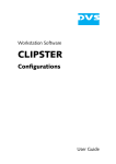
This user manual describes the specification of the positioning module displayed below, installation, how to use each
positioning function, programming and wiring with outer devices.
Number of
control axes
1-axis
Model
Related S/W package
G4F -POPA
G3F -POPA
G4F -POPB
G6F -POPA
2-axes
CPU
Pospack.exe
mfc42.dll
msvcrt.dll
msvcrt20.dll og70as.dll
POSPACK.EXE
positioning module
Driver
Stepping motor
Forward
Program
Multiphases
pulse
Set data
Read/
Write
Pulse
AMP
M
Reverse
▶GOF-PTUA
(Teaching terminal )
▶S/W package
(Pospack)
Fig. 1.1 Position control for stepping motor
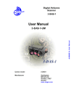
CPU
Driver
Positioning module
SERVO
SERVO motor
Forward
Program
Set data
Read/
Write
Deviation
D/A
counter
Converter
Speed
command
SERVO
M
AMP
Reverse
Interface
PG
Feed back pulse
Speed
GOF-PTUA
S/Package
Pulses in the counter
SERVO motor speed
Pulse
distribation
Fig.1.2 Position control for subo motor
1-1
Time
Chapter 1 Introduction
1.1 Features
The features of the position-decision module are as follows.
1) Positioning module can be used for GLOFA GM series and MASTER-K series.
(1) Positioning module for GM3 series and K1000S series: G3F-POPA(2-axes)
(2) Positioning module for GM4 & K300S series: G4F-POPA(1-axis), G4F-POPB(2-axes)
(3) Positioning module for GM6 & K200S series: G6F-POPA(2-axes)
2) Various control functions of positioning
(1) Max.300 position-decision setting data are allowed including position-decision address and operation method per axis.
(2) Linear control by position -decision control of each axis, separate position-decision by 1 position -decision data and
continuous position -decision by several data is available.
(3) Linear stepped control by position -decision control of 2 -axes, separate position-decision by 1 p osition -decision data and
continuous position -decision by several data is available.
(4) Various returning control functions to starting point.
A) Return to origin point can be performed by selection of one of those below ;
▶ origin point detection after near zero point Off
▶ origin point detection after deceleration at near zero point On
▶ origin point detection by origin point and upper/lower limit
▶ origin point detection by near zero point.
B) Position-decision control (floating point set setting) can be executed from random position to origin point of the
machine.
3) The number of positioning modules used at one base is unlimited.
4) Convenient maintenance and repairs.
G6F-POPA is designed to save position -decision data, parameters and other data in the flash memory of positioning
module.
1-2
Chapter 1 Introduction
1.2 Features of position-decision control function
Summary of positioning control function will be described.
1.2.1 Positioning control function
Summary of positioning by positioning datawill be described below.
1) Linear position-decision control
▶ Available operation modes are single, repeated, auto and continuous operation.
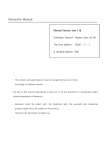
(1) 1-axis linear positioning control
Positioning of assigned axis is controlled from start address (presently stopped position) to target position.
Control by absolute method (Absolute Coordinates)
A) Positioning is controlled from start address to target position.
B) Shift direction is decided by start address and target address.
[ Ex. ]
When operated with the target of positioning address values of 5,000 & 15,000 if start address is 10,000,
Positioning if target is 5,000
5,000
10,000
Start address
15,000
Position-decision if target is 15,000
Control by incremental method (Relative Coordinates)
A) Positioning is controlled as much as target at start address.
B) Shift direction is decided by signals(+/ -) of shifting amount.
- If the signal of shifting amount is + (or no signal) incremental direction
: position decided to forward direction(address)
- If the signal of shifting amount is- decrement direction : position decided to reverse direction(address)
[ Ex. ]When operated with the target of shifting amount of 5,000(+5,000) and –5,000 if start address is 10,000.
Position-decision if target is -5,000
5,000
10,000
15,000
Start address
Direction if the signal is minus
Positioning if target is 5,000(+5,000)
Direction if the signal is plus
1-3
Chapter 1 Introduction
(2) 2-axes linear interpolation control
Linear interpolation control is performed at start address(presently stopped position) using assigned 2-axes.
Control by absolute method (Absolute Coordinates)
A) Linear interpolation control is performed from start address to target address wsing 2-axes.
B) Travel direction is decided by start point address and specified address of each axis.
[ Ex. ]
When operated with the target of positioning address of axis1: 2,000 & axis2: 5,000 if start point address is axis1 :
1,000 & axis2 : 2,000.
Axis1
2,000
Start point address
(2,000,1,000)
Specified address
(5,000, 2,000)
1,000
Positioning
Axis2
0
2,000
5,000
Control by incremental method (Relative Coordinates)
A) Positioning is controlled from start point a ddress to the position, which includes travel direction and travel value
assigned as a target per axis.
B) Travel direction of each axis is decided by travel value sign of each axis.
-
If the sign of shifting amount is + (or no sign) incremental direction
: positioning decided to forward direction(address)
- If the signal of shifting amount is- decrement direction : positioning decided to reverse direction(address)
[ Ex. ]
When operated with the target of travel value of axis1 :1,000 & axis2: 3,000 if start point address is axis1 :1,000 &
axis2 : 2,000.
Axis1
2,000
Start point address
(2,000,1,000)
Shift position when target
travel value is axis1: 1,000 &
axis 2: 3,000
1,000
positioning
Axis2
0
2,000
5,000
1-4
Chapter 1 Introduction
2) Speed control
positioning control is performed at the specified speed until deceleration stop command (POS ζ_STP, POS ζ_TMP) is
input after positioning start (POSζ_AST) is executed.
▶ Available operation mode is constant operation.
Speed
Dwell time
Time
On
positioning start
(POSζ_AST)
On
Busy
(POSζ_SRD, ST6[3])
On
Deceleration stop
Command (POSζ_STP)
3) Speed/position switching control
If speed/position switching signal is input via positioning module outside starting from speed control by positioning start
(POSζ_AST) and then changed into position control, the position is decided as much as travel value set as a target.
▶ Available operation mode is positioning constant operation.
Speed
Speed control
Position control
Target travel value
Dwell time
Time
On
Positioning start
(POSζ_AST)
On
Busy
(POSζ_SRD, ST6[3])
On
External speed/position
switching signal
1-5
Chapter 1 Introduction
1.2.2 Introduction of the operation mode
▶Positioning module can be set by positioning data user -defined in combination with control method (position control,
speed control, speed/position switching control), positioning address, operation method, etc.
▶Max.300 positioning setting data are allowed at step No. 0– 299 per axis..
Positioning data
Step
No.
Coordinat
es
Override
Operation
method
Invalid
/valid
Setting range/type
0
~
299
Absolute/
Relative
Allowable/
Prohibited
Continuo
us/
Complete
Invalid
/
Valid
Operation
mode
Single
Repeated
Auto
Continuous
Constant
Constant(Posi
tion)
Address
M code
Speed
No.
Dwell
(x 10 ㎳)
-16,744,447
~
16.744,447
0
~
255
0
~
127
0
~
999
▶P ositioning operation by 1 positioning data and positioning operation by several positioning data at single positioning
start(POSζ_AST :rising edge ↑) are respectively decided according to user-set operation mode to the positioning data.
1) Single operation mode (positioning complete)
(1) Positioning is complete upon positioning executed to the target position by positioning start(POS ζ_AST :rising edge
↑) and the dwell time elapsed.
(2) Positioning complete in this operation mode can be used for the operation mode of t he last positioning data in auto operation mode and continuous operation mode.
(3) Operation direction is decided according to position address value.
(4) Operation pattern is of trapezoid with acceleration, constant, and deceleration stages according to set spee d and position data,
however the following operation pattern may be produced in compliance with set value.
a) Normal operation pattern
Accelerated
Speed
Constant
Decelerated
Dwell time
Time
On
Positioning start
(POSζ_AST)
On
Busy
(POSζ_SRD, ST6[3])
On
In acceleration
(POSζ_SRD, ST1[3])
On
In constant
(POSζ_SRD, ST1[2])
On
In deceleration
(POSζ_SRD, ST1[1])
On
In dwell
(POSζ_SRD, 1[0])
On
Position. passing time
Position passing
signal (POSζ_SRD,
On
Positioning
complete(POSζ_SRD,
b)
Abnormal operation pattern
1-6
Chapter 1 Introduction
If operation speed is set larger than position travel value
If operation speed is set the same as bias speed
Speed
Dwell time
time
타임
Positioning start
Dwell time
Bias speed
Positioning start
(POSζ_AST)
(POSζ_AST)
Busy
Busy
(POSζ_SRD, ST6[3])
(POSζ_SRD, ST6[3])
In acceleration
In acceleration
(POSζ_SRD, ST1[3])
(POSζ_SRD, ST1[3])
In constant
In constant
(POSζ_SRD, ST1[2])
(POSζ_SRD, ST1[2])
In deceleration
In deceleration
(POSζ_SRD, ST1[1])
(POSζ_SRD, ST1[1])
In dwell
In dwell
(POSζ_SRD, 1[0])
(POSζ_SRD, 1[0])
Position passing
signal(POSζ_SRD,
Position passing
signal (POSζ_SRD,
Positioning
complete(POSζ_SRD,
Positioning
complete(POSζ_SRD,
2) Repeated operation mode (positioning complete)
(1) Positioning is complete upon positioning executed to the target position by start command(POS ζ_AST :rising edge
↑) and the dwell time elapsed.
(2) The pattern of repeated operation mode is the same as separate operation, however the ne xt operation is decided by
operation step No. which is set at assignment command of operation step No. (POS ζ_SMC :rising edge ↑) previously
executed after positioning is complete. Thus, if assignment command of operation step No. (POS ζ_SMC) is not
previously executed,
step No. “0” is assigned and then operated at the next start command(POSζ_AST).
Accordingly it is very useful in the system where several operation steps are repeated.
(3) Operation direction is decided according to position address value.
(4) Operation pattern
Speed
Start op. step No.:0
On
Op.: single
Op.:repeated
Op. :single
Op.:repeated
Op. step No.:0
:0
Op. step No.:1
Op. step No.:0
Op. step No.:1
On
On
On
Positioning
start
On
On
On
Busy
(POSζ_SRD, ST6[3])
1-7
On
Time
Chapter 1 Introduction
3) Auto-operation mode (positioning complete)
(1) Positioning is complete upon positioning executed to the target position
by positioning start(POSζ_AST :rising edge ↑) and the dwell time elapsed.
(2) Operation step (present operation step No. + 1) position is decided for operation in this mode without additional
positioning start(POSζ_AST).
(3) Accordingly, operation mode of the last operation step shall be set to single operation mode or repeated operation
mode.
(4) Several operation steps of auto-operation mode can be successively executed.
(5) Operation direction is decided according to position address value.
(6) Operation pattern
Spee
Start op. step No.:0
Op. : auto
Op. step No.:0
Op. : auto
Op. step No.: 1
Op. :single
Op. :single
Op. step No.: 2
Op. step No.: 3
On
Time
On
Positioning start
(POSζ_AST)
On
On
Busy
(POSζ_SRD, ST6[3])
4) Continuous operation mode (positioning complete)
(1) Positioning is complete upon positioning executed t o the target position without stopping operation step set to
continuous operation mode by startcommand (POSζ_AST :rising edge ↑) and the dwell time elapsed.
(2) Accordingly, operation mode of the last operation step shall be set to separate operation mode
or repeated operation mode.
(3) Continuous operation command(POSζ_NM:rising edge ↑) is available if next step position and speed are desired
before the presently engaged operation step reaches the target position.
However, continuous operation command(POSζ_NM) can be executed only at constant speed.
(4) Only the same direction is available for continuous operation mode, and operation direction is decided according to
position address value.
(5) Operation pattern
Speed
Continuous
op.com(POSζ _
NM)
Operation single
Op. step No. : 1
Op.:continuous
Op. step No. : 0
Time
On
Positioning start
(POSζ_AST)
On
Busy
(POSζ_SRD, ST6[3])
1-8
Chapter 1 Introduction
5) Constant operation mode (positioning incomplete)
(1) In constant operation mode, the operation at speed set without target position is continued by speed control operation.
(2) Since constant operation is not the positioning operation, it displays “ 0” for present position and is switched over to
undecided starting point state even if the starting point has been previously decided.
▶G3F-POPA, G4F-POPB, G6F-POPA : Dwell time is available but positioning complete signal is not.
▶G4F-POPA : Dwell time & positioning complete signal are unavailable.
(3) Accordingly, if the next operation step is at decided starting point state, returning to s tarting point shall be executed or
operation after fixed starting point setting shall be executed.
(4) If confronted by deceleration stop command ( P O Sζ_STP:rising edge ↑) in constant operation, the correspondent step
operation is regarded as complete leading to the next operation step of position data at restart.
(5) If confronted by deceleration stop command( P O S ζ_STP) in acceleration stage, constant stage, deceleration stage of
the constant operation, it stops as decelerated.
(6) Operation direction is decided according to the prior position address.
(However, G6F-POPA is decided according to position address sign)
(6) Operation pattern
Spee
Op. : constant
Op. step No. : 0
Dwell time
On
Positioning start
(POSζ_AST)
On
Busy
(POSζ_SRD, ST6[3])
On
Decel. stop
com(POSζ_STP)
1-9
Time
Chapter 1 Introduction
6) Positioning constant operation mode (positioning complete)
(1) If an outer input signal of speed position control -switching signal is input in speed control operation,
positioning constant operation is changed into position control operation to regard the signal -detected
position address value as “ 0” and execute positioning upto target position (position address value) set to
position data to finish positioning upon the dwell time elapsed.
▶In G6F- POPA positioning module, if stopped during operation as decelerated by deceleration stop
command( P O Sζ_STP:rising edge ↑), the correspondent step operation is regarded as incomplete leading to
the same step number operation as position data at restart.
▶ The outer input signal of speed/position control-switching signal is valid only in positioning constant
operation mode.
(2) Positioning constant operation is available for positioning ope ration starting from the position of sensor input
point via marker sensor input at packer or for its equivalent.
(3) Deceleration stop command( P O Sζ_STP ) is available at acceleration stage of positioning constant operation,
however speed/position control-switching signal input is available only at constant stage.
▶Error occurs if speed position control-switching signal is input during acceleration.
(4) If the position address is set smaller than positioning amount by deceleration inclination in position -decision
constant operation, positioning module re-calculates the deceleration inclination for operation.
Accordingly, stop can be followed as decelerated abruptly rather than deceleration inclination set by
parameters.
(5) Operation pattern
Spee
Op.:pos-deci constant
Op. step No. : 0
On
Time
Speed
control
Pos.
control
Positioning start
(POSζ_AST)
On
Busy
(POSζ_SRD, ST6[3])
On
Speed/position
Control switching signal
1-10
Chapter 1 Introduction
1.2.3 Introduction of acceleration/deceleration processing
▶Applied to start point & stop point of positioning operation, starting point returning high -speed operation and jog high speed operation, and also to continuous operation command(POS ζ_NM:rising edge ↑), speed change
command(POSζ_VCG:rising edge ↑) and speed override command(POSζ_OR:rising edge ↑) in positioning operation.
However, error may occur if deceleration stop command( P O Sζ_STP ) is used during acceleration/deceleration staged
operation at continuous operation command(POS ζ_NM), speed change command(P OSζ_VCG) and speed
override(POSζ_OR) in positioning operation.
▶Acceleration/deceleration time shall be set in unit of axis at parameters of S/W package.
▶Setting range is 0 ~ 999(Unit: 10 ㎳) per axis.
1) Acceleration time : Time required to reach speed limit set at parameter from speed“0”(stop state).
▷It means the time required to reach speed limit from bias speed if bias used.
(Bias speed and speed limits can be set at parameters.)
2) Deceleration time : Time required to reach speed“0”(stop state) from speed limit set at parameter
▷ It means the time required to reach bias speed from speed limit if bias used.
Speed limit
Speed
Setting speed
Actual decel. time
Actual accel. time
Time
Accel. time
Decel. time
▶ Terms
Speed limit : Max. speed when position is decided as set within the speed limits in parameter items of S/W package.
Setting speed : Speed data value actually operated by position data.
Actual acceleration time : Time required to reach speed value set to speed data from speed “0”(stop state).
Actual deceleration time : Time required to reach speed “0”(stop state) from speed value set to speed data.
1-11
Chapter 1 Introduction
1.2.4 Introduction of starting
▶If stopped by stop causes in position controlling (POSζ _ SRD, ST6[3]), positioning can be executed at stopped position
address value by restart.
▶Start type is of 1)positioning start, 2)interpolation positioning start, 3) positioning start to return to orig in point, 4)jog
command & 5)inching command.
▶If start executed, surely check that operation signal(POSζ _SRD, ST6[3]) is at“Off”state.
1) Positioning start(POSζ _AST)
; A command to start operation by parameters, position data and speed data set per axis of positioning module.
2) Interpolation positioning start(POSζ _INT)
(1) A command only available for 2 -axes positioning module to perform operation in a straight shift channel as allowed
by 2-axes.
(2) Take preautions for interpolation positioning start at which 2-axes are simultaneously operated.
a) Operation-related subdata is operated as based on X-axis.
; position data(step, coordinates, override, operation method, invalid/valid, operation mode, position address, M
code, speed No., dwell time)
; M code mode among parameter items
b) Classified into major axis and minor axis according to positioning address amount of X- a x i s & Y-axis at
interpolation positioning start.
; Speed data of minor axis is calculated as follows.
Major axis speed X Minor axis length
Minor axis speed
=
Major axis length
▷ Terms
major axis : X-axis or Y-axis of whichever positioning address amount is larger in applicable operation step No.
minor axis : X-axis or Y-axis of whichever positioning address amount is smaller in applicable operation step No.
; Speed, acceleration time, deceleration time and bias speed of minor axis will be recalculated at this time.
c) Operating items based on setting value per axis are
;Backlash compensation, S/W upper limit, S/W lower limit, position passing time and zone setting area of
parameter items
(3) Available operation mode is separate operation, repeated operation and auto-operation only.
3) Positioning start to return to starting point (POSζ _ORG)
▶An operation command to find origin point of the machine according to origin point return -processing method by direction,
correction, spee d(high/low), address and dwell time set at origin point return -parameters of each axis. And if complete signal of
return to origin point is On, origin point return-operation of the machine is complete.
4) Jog command(POSζ_JOG)
▶As a test operation function it is necessary to check system operation, wiring and position address.
▶Jog operation is available at high speed and low speed.
(1) Jog high-speed operation : acceleration/deceleration pattern available.
(2) Jog low-speed operation : acceleration/deceleration pattern unavailable.
5) Inching command(POSζ _INC)
▶One of manual operation methods used to process minute operation as determinate operation.
▶J og command operation is hard to move to exact position because operation starts and stops according to the com mand, but via
the inching command with travel value easily set as desired the target is easy to reach.
▶Thus, after rapid move near to work position by jog command, perform operation by inching command for minute move to the exact
work position to reach.
1-12
Chapter 1 Introduction
1.2.5 Introduction of the return to origin point
▶Origin point return is executed to check origin point of the machine when powered.
▶Various methods for origin point return are available according to the structure and stop accuracy of the machine, while
approximate origin point (adjacent DOG) method is used for LG positioning module.
▶If origin point position is decided to origin point return, detection signal of origin point is not used during positioning
operation.
1) Near zero point(adjacent DOG) methods
4 near zero point(adjacent DOG) methods for origin point return-processing are as follows.
(1) origin point detection after near zero point Off
(2) origin point detection after deceleration at near zero point On
(3) origin point detection by origin point and upper/lower limit
(4) origin point detection by near zero point
2) Parameter items of S/W package which influence origin point return are as follows.
(1) origin point return-direction
(2) origin point compensation
(3) origin point return-speed( high/low )
(4) origin point address
(5) dwell time for origin point return
1-13
Chapter 2 Specification
Chapter 2 Specification
2.1 General specification
General specification of GLOFA GM series and MASTER-K series is described in Table 2.1.
Related
specification
No.
Item
Specification
1
Operating
temperature
0 ~ 55°C
2
Storage
temperature
−25 ~+70 °C
3
Operating
humidity
5 ~ 95%RH, No condensation
4
Storage
humidity
5 ~ 95%RH, No condensation
If vibrated intermittently
Frequency
5
6
7
Viration
Shocks
Noise
immunity
Sweep count
Amplitude of
vibration
Acceleration
10 ≤ f < 57Hz
−
57 ≤ f ≤ 150Hz
9.8m/s 2{1G}
If vibrated continuously
Frequency
Acceleration
10 ≤ f < 57Hz
57 ≤ f ≤ 150Hz
−
4.9m/s2{0.5G}
The number
0.075mm
−
Amplitude of
vibration
0.035mm
−
10 times each
direction of X,
Y, Z
IEC61131-2
• Max. shock acceleration : 147 m/s2{15G}
• Duration time : 11ms
• pulse wave : half sine wave pulse (3 times each direction of X, Y, Z)
IEC61131-2
Square wave
impulse noise
± 1,500 V
Based on LG
test spec.
voltage : 4kV (contact discharge)
IEC61131-2
IEC1000-4-2
Electrostatic
discharge
Radiated
electromagnetic
field
Fast
Transient
/ burst noise
27 ~ 500 MHz,
IEC61131-2,
IEC1000-4-3
10 V/m
Class
Power
module
Digital
input/output
(24V or
above)
Digital input/output
(less than 24V)
Analog input/output
comm. interface
Voltage
2kV
1kV
0.25kV
8
Operating
atnospher
No corrosion gas or dust allowed
9
Altitude
fruse
2,000m or below
10
Pollution
degree
11
Cooling
method
2
or below
Natural air-cooled
2-1
IEC61131-2
IEC1000-4-4
Chapter 2 Specification
Remark
1
2
3
1) IEC(International Electro technical Commission )
:An international nongovernmental organization which promotes internationally cooperated
standardization in electric/electronic fields, publishes international standards and
manages applicable estimation system related with.
2) Pollution degree
: An index indicating pollution level of the application environment which decides
insulation performance of the device. Pollution degree 2 means that only non conductive contamination occurs. However temporary conduction may occur according to
condensation.
2-2
Chapter 2 Specification
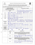
2.2 Performance specification
Performance specification of positioning module is described in Table 2.2.
Specification
Item
G3F-POPA
G4F-POPB
G6F-POPA
G4F-POPA
Number of control axes
2-axes
1-axis
Input/output occupied points
64
32
Interpolat ion function
2-axes linear interpolation(simultaneously2-axes, separately2-axes)
Control method
No
PTP(Point to Point),linear interpolation, speed control, speed position switching control
*1
Control Unit
Pulse
Positioning data
300 data per axis ( operation step No. : 0 ~ 299)
S/W package
Peripheral
device
Teaching module
available
available
Available
Positioning method
unavailable
available
Absolute method/relative(incremental) method
Position address range
setting range : -16,744,447 ~ 16,744,447
Max. 200Kpps
Speed
speed setting range: 10 ~ 200,000
speed setting data: 0 ~ 127
Operation pattern : trapezoid method
acceleration time : 10 ~ 9,990 ㎳
deceleration time : 10 ~9,990 ㎳
Acceleration/deceleration
processing
Positioning
PTP, speed control
Backlash compensation
0 ~ 999 Pulse
Bias speed
10 ~ 200,000
S/W upper limit setting range : 0~ 16,744,447
S/W upper/lower limit
S/W lower limit setting range : -16,744,447~ 0
Zone setting
setting number: 3
setting range : -16,744,447 ~ 16,744,447
Position passing time
Setting time : 0 ~9,990 ㎳
Single operation, repeated operation, auto-operation, continuous operation
Operation mode
Constant operation,
Positioning constant operation
Compensatio n
Speed
Low
speed setting range: 10 ~ 100,000
setting range : -16,744,447 ~ 16,744,447
Dwell time
origin
point
setting time : 0~9,990 ㎳
Methods by near zero point signal and origin point signal
1
Method
Manual
speed setting range: 10 ~ 200,000
Address
Return
to
operatio
n
setting range : -999 ~ 999 Pulse
High
1) origin point detection after near zero point Off
2) origin point detection after deceleration at approximate origin point On
2
origin point detection by origin point and upper/lower limit
3
origin point detection bynear zero point
JOG
Yes
Manual pulse generator(MPG)
Yes
Inching
No
No
ROM/RAM teaching
ROM teaching
setting range : 1 ~ 99
Speed/position teaching
ROM teaching
Floating point set
Others
-
available
Present position preset
available
M code mode
With, After, None
Continuous operation(Next move)
available
Speed override
Setting range : 10 ~ 150%
Position return prior to manual
operation
available
Setting operation step No.
Connection connector
available
25-pin per axis
Isolation method
34-pin
37-pin
16-pin
Photo-coupler isolation between input terminal and PLC power (Isolation unavailable between channels)
Current consumption
390 ㎃
350 ㎃
280 ㎃
280 ㎃
Weight
537 g
296 g
137 g
296 g
*1: G6F-POPA available only
2-3
Chapter 2 Specification
2.3 Input/output interface specification with external device
Input/output interface with the External device is described.
2.3.1
Input specification
Signal
Rated input
voltage/curr
ent
Used voltage
range
On voltage
Off voltage
Input
resistance
Near zero point
External upper limit
External lower limit
Emergency stop
DC 24V/10 ㎃
DC 24V/10 ㎃
DC 24V/10 ㎃
DC 24V/10 ㎃
DC 20.4~26.4V
DC 20.4~26.4V
DC 20.4~26.4V
DC 20.4~26.4V
DC 16V or above
DC 16V or above
DC 16V or above
DC 16V or above
DC 4V or below
DC 4V or below
DC 4V or below
DC 4V or below
Approx. 2.2㏀
Approx. 2.2㏀
Approx. 2.2㏀
Approx. 2.2㏀
DC 24V/10 ㎃
DC 20.4~26.4V
DC 16V or above
DC 4V or below
Approx. 2.2㏀
G3F-POPA/G4F-POA/G4F-POPB
Origin point
1 0㎲
or
1 0㎲
10㎳
DC 5V
DC 12V
1) Pulse width
Manual pulse generator
1㎳
3㎲
below
below
below
below
or
or
DC 4V or above
DC 1V or below
Approx. 430Ω
DC 10.8~13.2V
DC 8V or above
DC 2V or below
Approx. 430Ω
3㎳
or
or
or
or
On:0.1㎳ or below
DC 4.25~5.5
1.5㎳
1.8㎳ or below
or
o r 1 . 5㎳
Dutyrate50%
or
Position address value increased if phase A input
pulse is ahead of phase B input pulse.
0 . 5㎳
DC 24V/10 ㎃
1.8㎳
1.8㎳
1.8㎳
1.8㎳
G6F-POPA
G3F -POPA/G4F-POA/G4F-POPB
3㎲
or
or
2)Phase difference
Positioning
constant operation
or
Response time
DC 20.4~26.4V
Position address value decreased if phase B input
pulse is ahead of phase A input pulse.
or
DC 16V or above
2-4
DC 4V or below
Approx. 2.2㏀
On:1.8㎳ or below
Chapter 2 Specification
2.3.2 Output specification
Signal
Rated load
voltage
Operating load voltage
range
Max. load current
DC 5V
DC 4.75~5.25V
DC 20.4~26.4V
70㎃
70㎃
DC 24V
Class
Forward direction
Forward rotation
FP(CW)
Pulse output
(forward direction pulse,
reverse direction pulse)
A
Type
RP(CCW)
FP(pulse)
B
Type
RP(sign)
2-5
Reverse rotation
Max. voltage descent when
powered On
DC 0.3V or below
DC 0.3V or below
Reverse direction
Forward rotation
Reverse rotation
Chapter 2 Specification
2.4 External interface connector
2.4.1 Connector’s pin arrangement
Number, signal name, signal contents, signal’s input/output direction, s h a p e o f t h e
connector pins are described.
Pin No.
G3FPOPA
G4FPOPB
Input/output direction
G6FPOPA
G4FPOPA
Signal
2
26
1
2
X_FP
X-axis forward direction pulse output
11
4
2
3
X_RP
X-axis reverse direction pulse output
2
25
3
-
Y_FP
Y-axis forward direction pulse output
11
3
4
-
Y_RP
Y-axis reverse direction pulse output
24
18
5
9
X_ZOC
X-axis origin point input(DC24V)
25
28
6
4
X_ZL
X-axis origin point input(DC5V)
15
6
7
8
X_ZCOM
X-axis origin point input Ground
24
17
8
-
Y_ZOC
Y-axis origin point input(DC24V)
25
27
9
-
Y_ZL
Y-axis origin point input(DC5V)
15
5
10
-
Y_ZCOM
Y-axis origin point input Ground
22
22
11
12
X_ORG
X-axis near zero point switch input (A contact)
18
21
12
13
X_OV-
X-axis external lower limit switch input (B contact)
3
22
13
14
X_OV+
X-axis external upper limit switch input (B contact)
-
-
14
-
X_VTP
X-axis speed position switching input (A contact)
22
31
15
-
Y_ORG
Y-axis near zero point switch input (A contact)
18
20
16
-
Y_OV-
Y-axis external lower limit switch input(B contact)
3
9
17
-
Y_OV+
Y-axis external upper limit switch input(B contact)
-
-
18
-
Y_VTP
Y-axis speed position switching input (A contact)
19
32
19
15
EMG
E. stop switch input_ X/Y-axes common (B contact)
1
2
20
7
X_24V
X-axis pulse output, external power input terminal(D24V)
17
24
21
11
X_5V
X-axis pulse output, external power input terminal(DC5V)
10
1
23
22
23
1
X_GND
X-axis pulse output ground
1
2
24
-
Y_24V
Y-axis pulse output, external power input terminal(DC24V)
17
24
25
-
Y_5V
Y-axis pulse output, external power input terminal(DC5V)
10
1
23
26
27
-
Y_GND
Y-axis pulse output ground
2-6
Positioning
Module
Outer device
Chapter 2 Specification
21
11
33
32
33
34
35
4
5
13
14
9
16
INPUT COM
Input contact common
EMG
X_STOP, X_OV-, X_OV+, X_ORG, X_STOP
Y_STOP, Y_OV-, Y_OV+, Y_ORG, Y_STOP
-
10
PO_COM
Input contact Vcc Common
(If DC24V used for outer input power, let it connected to
DC24V, if DC5V used, let it connected to DC5V)
30
-
-
MPG_A
Manual pulse generator phase A input
16
8
-
-
MPG_AGND
Manual pulse generator phase A Common Ground
8
29
-
-
MPG_B
Manual pulse generator phase B input
7
7
-
-
MPG_BGND
Manual pulse generator phase B Common Ground
6
-
-
6
FG
Frame Ground
12
13
14
20
23
12
15
16
19
34
28
29
30
31
36
37
5
Unused
2-7
Chapter 2 Specification
2.4.2 Internal circuit
Internal circuit for connecting interface with the external device of the positioning
module is described
Pin No.
Class
Pulse
output
terminal
Starting
point input
Internal circuit
Signal
G3F-
G4F-
G6F-
G4F-
POPA
POPB
POPA
POPA
1
2
20
7
X_24V
X-axis pulse output, external supplied p ower (DC 24V)
17
24
21
11
X_5V
X-axis pulse output, external supplied power (DC 5V)
2
26
1
2
X_FP
X-axis forward direction pulse output
11
4
2
3
X_RP
X-axis reverse direction pulse output
10
1
23
22
23
1
X_GND
X-axis pulse output ground
1
2
24
Y_24V
Y-axis pulse output, external supplied power (DC 24V)
17
24
25
Y_5V
Y-axis pulse output, external supplied power (DC 5V)
2
25
3
Y_FP
Y-axis forward direction pulse output
11
3
4
Y_RP
Y-axis reverse direction pulse output
10
1
23
26
27
Y_GND
Y-axis pulse output Ground
24
18
5
9
X_ZOC
X-axis phase Z input_ Open Collector
(DC 24V)
25
28
6
4
X_ZL
X-axis phase Z input_Line Driver
(DC 5V)
15
6
7
8
X_ZCOM
X-axis phase Z input Ground
24
17
8
Y_ZOC
Y-axis phase Z input_ Open Collector
(DC 24V)
25
27
9
Y_ZL
Y-axis phase Z input_Line Driver
(DC 5V)
15
5
10
Y_ZCOM
Y-axis phase Z input Ground
2-8
-
-
Chapter 2 Specification
Pin No.
Class
Internal circuit
Signal
G3FPOPA
G4FPOPB
G6FPOPA
G4FPOPA
18
21
12
13
X_OV-
X-axis external lower limit signal input (B contact)
3
10
13
14
X_OV+
X-axis external upperr limit signal input (B contact)
22
22
11
12
X_ORG
X-axis near zero point signal input (A contact)
-
14
-
X_VTP
X-axis speed position switching signal input (A contact)
21
11
33
32
33
34
35
16
INPUT
_COM
Input signal common
18
20
16
Y_OV-
Y-axis outer bottom limit signal input(B contact)
3
9
17
Y_OV+
Y-axis outer top limit signal input(B contact)
22
31
15
Y_ORG
Y-axis approximate starting point signal input (A contact)
-
18
Y_VTP
Y-axis speed position switching signal input (A contact)
21
11
33
32
33
34
35
INPUT
_COM
Input signal common
19
32
19
15
EMG *1
Emergency stop signal input
_ X/Y-axis common (B contact)
21
11
33
32
33
34
35
16
INPUT
_COM
Input signal common
9
30
MPG_A
Manual pulse generator phase A input
MPG_
AGND
Manual pulse generator phase A Common
X-axis
input signal
Y-axis
input signal
-
Emergency
stop signal
Manual pulse
8
8
2-9
-
-
Chapter 2 Specification
16
29
MPG_B
Manual pulse generator phase B input
generator
input
7
7
MPG_
BGND
Manual pulse generator phase B Common
External
power
4
5
13
14
-
10
INPUT
_COM
Input contact Ground Common
EMG
X_STOP, X_OV-, X_OV+, X_ORG, X_STOP
Y_STOP, Y_OV-, Y_OV+, Y_ORG, Y_STOP
FG
6
-
-
6
FG
Frame Ground
*1:If emergency stop signal is used in G3F-POPA, only independent X-axis(19) or Y-axis(19) shall be used.
2-10
Chapter 2 Specification
2.5 Designation and function of the parts
1) G3F-POPA
2) G4F-POPA
3)G4F-POPB
4)G6F-POPA
G4F -POPB
G3F -P O P A
READY
BUSY
DIR
G4F -POPA
①
②
③
④
②
③
④
①
②
③
④
ERR
X
Y
RS232C
①
②
③
④
Y-BUSY
④②
X-BUSY
G6F -P O P A
⑤
INPU
T
⑤
⑤
Y
X
X/Y-
⑥
⑥
⑥
No.
①
②
③
Description
Ready signal
Ready signal of positioning module.
Busy signal
Turned “On”if each axis is in busy (operation) state.
DIR signal
▶On : forward pulse output
▶Off : reverse pulse output
ERR signal
▶G3F-POPA, G4F-POPA, G4F-POPB: turned on if error occurs.
④
▶G6F-POPA : flickering if error occurs.
1) Flickering at intervals of 0.5 sec. : serious error for pulse output prohibited.
2) Flickering at intervals of 1.0 sec. : trivial error for pulse output.
RS-232C connector
⑤
▶for connection with S/W package.
▶As for G6F -POPA, connection available via communication port of CPU module
(However, CPU module shall be in STOP state at this time)
⑥
Externalr interface connector
for connection with drive device.
2-11
⑥
GN
5V
24V
GN
5V
24V
EMG
VTP
OV+
Y
OVORG
VTP
OV+ X
OVORG
ZCOM
Y
ZL
ZOC
ZCOM
X
ZL
ZOC
RP
Y
FP
RP
X
FP
Chapter 2 Specification
2.6 Connector’s pin arrangement
Connector’s pin arrangement for connection with external device of positioning module is described
Connector’s pin arrangement
Model
External interface connector
RS-232C connector
Pin arrangement of X-axis & Y-axis.
G3FPOPA
1
2
10
4
11
5
12
6
13
7
14
15
17
18
19
20
21
22
1
2
3
4
5
6
G4FPOPA
7
8
9
14
15
16
1
2
3
4
5
6
23
24
19
15
25
18
37
16
26
17
36
24
25
23
27
16
35
7
17
15
34
8
18
28
9
19
29
14
33
package
16
1
13
14
9
10
12
13
8
6
11
G4FPOPB
G6FPOPA
3
Connected with S/W
installed in computer
20
30
13
32
10
21
31
12
31
12
33
34
2
8
3
9
4
32
10
29
9
28
8
27
7
26
6
25
5
24
4
23
3
22
2
21
1
20
▶Direct connection is unavailable between G6F-POPA positioning module and computer.
Use RS -232C port of GM6 CPU module or k200s cpu module for positioning module operation using S/W
package,
and perform operation with S/W package after operation mode of CP U module is let positioned at STOP
state.
2-12
5
22
11
30
11
7
Chapter 3 Functions
Chapter 3 Functions
3.1 Positioning control
Positioning control is classified into position control, speed control, speed/position switching control.
3.1.1 Position control
1)
1-axis position control
Positioning of assigned axis is controlled from start point address (presently stopped position) to
specified address (travel value).
(1) Control by absolute method (Absolute Coordinates)
A) Positioning is controlled from start point address to specified address (at positioning data).
B) Positioning control is executed as based on the address(origin point address) assigned at origin point return.
B) Travel direction is decided according to start point address & specified address.
▶start point address < specified address : position decided forward
▶start point address > specified address : position decided reverse
[ Ex. ]
▷If start point address is 1000 and ▷specified address is 8000, forward travel value is 7000(8000-1000).
0
100
8000
Travel value:7000
Start point address
Specified address
▷ Setting in S/W package
Position data items
Step
No.
Setting
0
Coordin
ates
Absolut
e
Override
Operation
method
Invalid
/valid
Operation
mode
Address
M code
Speed No.
Dwell
(x 10㎳)
Enable
Continuous
Valid
Single
8000
0
0
0
3-1
Chapter 3 Functions
▷Program
Error infomation
operation
Program 3.1 Basic(setting of floating point set)
Remark
Control by absolute method (Absolute Coordinates) can be started at the state that origin point has been decided.
If started at the state that origin point has not been decided, error 76 occurs. Available operation modes are single, repeated, and continuous operation.
(2) Control by incremental method (relative coordinates)
A) Positioning is controlled at start point address as much as target travel value.
B) Travel direction is decided according to travel value sign.
▷If travel direction is + (or no sign)
: position decided forward (address incremental direction)
▷If travel direction is : position decided reverse (address decrement direction)
Start point address
Reverse
Forward
Travel direction if sign is+
Travel direction if sign is-
[ Ex. ] ▷If start point address is 5000 and ▷specified address is –7000, position is decided at -2000.
-
0
5000
Reverse pos. control(travel value-7000)
Specified address
Start point address
▷ Setting in S/W package
Position data items
Setting
Step
No.
0
Coordin
ates
Relative
Override
Enable
Operation
method
Continuous
▷Program
Program is the same as program 3.1.
3-2
Invalid
/valid
Valid
Operation
mode
Single
Address
M code
Speed No.
-7000
0
0
Dwell
(x 10㎳)
0
Chapter 3 Functions
2)
2-axes position control
Linear interpolation control is performed at start point address(presently stopped position) using assigned 2-axes.
(1) Control by absolute method (Absolute Coordinates)
A) Linear interpolation control is executed from start point address to specified address(assigned at positioning data) via 2-axes.
B) Positioning is controlled as based on the address assigned at origin point return.
C) Travel direction is decided according to start point address and specified address of each axis.
▶start point address < specified address : position decided forward
▶start point address > specified address : position decided reverse
Forward(Y)
Y2
Start point address
(X1, Y1)
Y, travel value
Specified address
(X2, Y2)
Y1
X & Y, linear interpolation operation
Reverse
Forward(X)
X1
X, travel value
X2
Reverse
[ Ex. ]
▷If start point address is (1000, 4000) and ▷specified address is (10000, 1000), the operation isas follows.
(Y)
4000
Start point address
Y, travel value
(1000-4000=-3000)
Specififed address
1000
(X)
0
100
500
1000
X, travel value(10000-1000=9000)
▷Setting in S/W package
Position data items
Step
No.
X-axis setting
0
Y-axis setting
0
Coordin
ates
Absolut
e
Absolut
e
Override
Operation
method
Invalid
/valid
Operation
mode
Address
M code
Speed No.
Dwell
(x 10㎳)
Disable
Continuous
Valid
Single
10000
0
0
0
Disable
Continuous
Valid
Single
1000
0
0
0
3-3
Chapter 3 Functions
▷Program
X Axis
Info
Cancelled
if
output
prohibited by error
Y Axis
Info
Y Axis error information
Axis error information
Axis operation information
Undecided data for origin point of X(Y) axis
Undecided data for orogin point of X(Y) axis
Axis operation information
Program 3.2 Basic(setting of li near interpolation start _ floating point set)
starting point)
3-4
Chapter 3 Functions
Remark
Take preautions for linear interpolation start(POS■_INT:rising edge ↑) at which 2-axes are simultaneously operated.
1)Operation-related subdata is operated as based on X-axis.
; position data(step, coordinates, override, operation method, invalid/valid, operation mode, position address, M code, speed No., dwell time)
; M code mode among parameter items
2)Classified into major axis and minor axis according to positioning address amount of X-axis & Y -axis at interpolation positioning start.
; Speed data of minor axis is calculated as follows.
Minor
axis
speed
Major axis speed X Minor axis distance
Major axis distance
▷Terms
major axis : X-axis or Y-axis of whichever positioning address amount is larger in applicable operation step No.
minor axis : X-axis or Y-axis of whichever positioning address amount is smaller in applicable operation step No.
; Speed, acceleration time, deceleration time and bias speed of minor axis will be recalculated at this time.
3)Operating items based on setting value per axis are
;Backlash compensation, S/W upper limit, S/W lower limit, position passing time and zone setting area of paramete r items. Available peration mode
is single operation, repeated operation and auto -operation only.
4) If required time for moving a position address value to specified address exceeds 65,535㎳, error 89 occurs.
3-5
Chapter 3 Functions
(2) Control by incremental method (Relative Coordinates)
A) Positioning controlled to the position which includes travel direction and travel value as aimed at start point address per axis.
B) Travel direction of each axis is decided according to travel value sign of the axis.
- If travel value sign is + (or no sign )
: position decided forward (address incremental direction)
- If travel value sign is : position decided reverse (address decrement direction)
Forward(Y)
Y2
Start point address
(X1, Y1)
Y, travel value
Y1
Specified address
(X2, Y2)
X & Y, linear interpolation operation
Reverse
Forward (X)
X1
X, travel value
X2
Reverse
[ Ex. ]
▷If start address is (1000, 4000) and ▷target address is (9000, -3000), the operation is as follows.
(Y)
4000
Start point address
Y, travel value
(-3000)
Specified address
1000
(X)
0
100
500
1000
X, travel value (9000)
▷Setting in S/W package
X-axis setting
Step
No.
0
Coordin
ates
Relative
Y-axis setting
0
Relative
Position data items
Disable
Operation
method
Continuous
Invalid
/valid
Valid
Operation
mode
Single
Disable
Continuous
Valid
Single
Override
▷Program
Program is the same as program 3.2.
3-6
Address
M code
Speed No.
10000
0
0
Dwell
(x 10㎳)
0
1000
0
0
0
Chapter 3 Functions
3.1.2 Speed control (constant operation mode)
▶ Speed is controlled as set until deceleration stop command is input after executed bypositioning start.
(Origin point undecided if operation is stopped bydeceleration stop command)
▶Speed control includes forward start and reverse start.
Model
Forward direction start
Reverse direction start
Set position address value positive
Set position address value negative
G6F-POPA
(Ex. : 100, +1000)
(Ex. : -100, -1000)
1. If prior direction to constant operation start is 1 If prior direction to constant operation start is
forward, forward operation is continued,
reverse, reverse operation is continued,
2. If prior direction to constant operation start is 2. If prior direction to constant operation start is
reverse,
forward,
G3F-POPA
G4F-POPA
▷forward separate or repeated positioning
▷ reverse separate or repeated positioning
G4F-POPB
operation shall be performed at a constant
operation shall be performed at a constant
speed.
speed.
3.As specified in 1 & 2 above for execution of starting 3.As specified in 1 & 2 above for execution of starting
point decision
point decision
▶If speed control is applied, the following items of positioning data have no influence on constant operation mode.
Step
No.
Position data items
Coordin
ates
Override
Operation
method
Invalid
/valid
Operation
mode
Address
M code
Speed No.
Dwell
(x 10㎳)
Items with no influence
*1
*1: Only for G4F-POPA.
▶If M code applied, use “With”mode only.
(If “After”mode used, M code “On”signal is not output.)
▶Operation timing
Speed
Setting speed
Dwell
Time
On
Positioning start
(POS■_AST)
On
Busy
(POS■_SRD, ST6[3])
On
Deceleration stop command
(POS■_STP])
[ Ex. ]
▷Setting in S/W package(G6F -POPA)
forward direction
Step
No.
0
Coordin
ates
Relative
reverse direction
1
Relative
Direction setting
Disable
Operation
method
Continuous
Invalid
/valid
Valid
Operation
mode
Constant
Disable
Continuous
Valid
Constant
Override
3-7
Address
M code
Speed No.
100
0
0
dwell
(x 10㎳)
0
- 100
0
1
0
Chapter 3 Functions
▷Program
Program 3.3 Deceleration stop(return to origin point)
3-8
Chapter 3 Functions
3.1.3 Speed/position switching control (positioning constant operation)
▶If speed/position switching signal is input via positioning module outside while the axis set by positioning start controls speed, speed
control is switched to position control to decide position as much as target travel value set.
▶Speed/position switching control is processed by outer input signal of ”speed position switching input signal”in G6F -POPA and by
“deceleration stop command” in G3F-POPA, G4F-POPA & G4F-POPB.
▶Position-decision constant operation is available as directed forward and reverse.
Direction setting
Step
No.
Coordin
ates
Override
Operation
method
Invalid
/valid
Operation
mode
Address
M code
Speed No.
Dwell
(x 10㎳)
0
Relativ
e
Disable
Continuous
Valid
Constant
(position)
100*1
0
0
0
1
Relativ
e
Disable
Continuous
Valid
Constant
(position)
- 100*2
0
1
0
Forward
direction
Reverse
direction
Items with no influence
▷ Direction forward or reverse is decided according to value sign of position address in positioning constant operation.
(At this time all are processed by absolute method without distinction of methods absolute or relative)
*1 (forward direction) : when position address value is +
*2 (reverse direction) : when position address value is ▶Operation timing(G6F-POPA)
G6F-POPA at accelerated stage: speed pos. control switching signal / G3FPOPA, G4F-POPA, G4F-POPB :error 45 occurs if stop command is input.
Speed
Error 70 occurs if pos. data set of pos.-
Accelerated stage
dec.constant op. mode too small
Speed
Setting speed
Position control
control
Setting travel value
Dwell time
Time
On
Positioning start
(POS■_AST)
On
Busy
(POS■_SRD, ST6[3])
On
Speed/position switching
signal(external input signal)
On
Speed/position switching.
signal (POS■_SRD, ST5[0])
▶Program
Program is the same as program 3.3.
3-9
Chapter 3 Functions
3.2
Operation mode
▶Operation mode is to form various configurations required to operate positioning data and to process position data speed with each
operation step No.
▶Type of operation mode is as follows.
Control method
Operation mode
Others
Single
Repeated
Auto
Position control
Continuous
Speed control
Constant
Speed control
+position control
Positioning
constant operation
■Interpolation function unavailable
■S/W upper/lower limit detection unavailable
■Interpolation function unavailable
■Changeable from speed control to position control by
-deceleration stop function block[POS ζ_STP:rising edge ↑] in G3F -POPA,
G4F -POPA, G4F-POPB and
-external input signal of “speed position switching input signal” in G6F-POPA
■Interpolation function unavailable
▶The following rules are between operation modes.
n+1th operation
Nth operation
Single operation
Single
Repeated
Auto-
Continuous
Constant
operation
operation
operation
operation
operation
Operation
Operation
Operation
Operation
Operation
Positioning
Constant
operation
Operation
available
available
available
available
available
available
Operation
Operation
Operation
Operation
Operation
Operation
available
available
available
available
available
available
Operation
Operation
Operation
Operation
Operation
Operation
available
available
available
unavailable
unavailable
unavailable
Operation
Operation
Operation
Operation
Operation
Operation
available
available
unavailable
available
unavailable
unavailable
Operation
Operation
Operation
Operation
Operation
Operation
available
available
available
available
available
available
Positioning
Operation
Operation
Operation
Operation
Operation
Operation
Constant operation
available
available
available
available
available
available
Repeated operation
Auto-operation
Continuous operation
Constant operation
▶Operation mode is set at position data of S/W package.
▶ Max. 300 position data can be set per axis in the range of operation step No. 0 ~ 299.
Position data
Step
No.
Coordinat
es
Override
Operation
method
Invalid/v
alid
Setting range/type
0
~
299
Absolute
Relative
Enable
Disable
Continuous
Complete
Invalid
Valid
Operation
mode
Single
Repeated
Auto
Continuous
Constant
Con.(pos.)
Address
M code
Speed No.
Dwell
(x 10㎳)
-16,744,447
~
16.744,447
0
~
255
0
~
127
0
~
999
▶Positioning operation method by one positioning data per operation step or
by several positioning data via successive operation steps at a start command is decided according to operation mode user - defined at
each positioning data.
3-10
Chapter 3 Functions
3.2.1 Separate operation
1) Positioning is complete upo n positioning executed to the target position by one positioning start(POS ζ_AST :rising edge
↑) and the dwell time elapsed.
2) Positioning complete in this operation mode can be used for the operation mode of the last positioning data in auto operation mo de and continuous operation mode.
3) Operation direction is decided according to position address value.
4) Operation pattern is of trapezoid with acceleration, constant, and deceleration stages according to setting speed and position data,
however the following operation pattern may be produced in compliance with set value.
a) Normal operation pattern
Speed
Dwell Time
Time
On
Positioning start
(POSζ_AST)
On
BUSY
( POS ζ_SRD, ST6[3])
On
In acceleration
( POS ζ_SRD, ST1[3])
On
In constant
(POS ζ_SRD,ST1[2])
On
In deceleration
( POS ζ_SRD, ST1[1])
On
In dwell
( POS ζ _ S R D ,
1[0])
Position passing
signal(POS ζ_SRD, ST6[2])
On
On
Positioning complete
( POS ζ_SRD, ST6[4])
Abnormal operation pattern
If operation speed is set larger than position travel value
If operation speed is set the same as bias speed
Speed
Dwell
Time
Bias speed
On
Positioning start
BUSY
On
Positioning start
On
On
In acceleration
In acceleration
In constant
In deceleration
On
BUSY
On
In constant
On
In deceleration
On
On
In dwell Time
Position
passing signal
Positioning
complete
On
On
On
On
Positioning
complete
3-11
Chapter 3 Functions
[ Ex. ]
▷ Operation pattern
Speed
Start op. step No. : 0
Op. : single
Op. : single
Op. step No.: 0
Op.: single
Op. step No.: 1
Op.: single
Op. step No.: 2
Op. step No.: 3
Time
On
Positioning start
(POS■_AST)
On
BUSY
(POS ■_SRD, ST6[3])
▷Setting in S/W package
start commands
Step
No.
1
0
2
1
3
2
Number of program
4
3
Coordin
ates
Absolut
e
Absolut
e
Absolut
e
Absolut
e
Override
Operation
method
invalid/v
alid
Operation
mode
Address
M code
Speed No.
Dwell
(x 10㎳)
Disable
Continuous
Valid
Single
100
0
0
0
Disable
Continuous
Valid
Single
200
0
1
0
Disable
Continuous
Valid
Single
300
0
0
0
Disable
Continuous
Valid
Single
400
0
1
0
▷ Program
Program 3.4 Single operation (return to origin point)
3-12
Chapter 3 Functions
3.2.2 Repeated operation
1)
2)
3)
4)
Positioning is complete upon positioning executed to the target position by one start command(POS ζ_AST :rising edge
↑) and the dwell time elapsed.
The pattern of repeated operation mode is the same as single operation, however the next operation is decided by
operation step No. which is set at change command of operation step No. previously executed after positioning is
complete.
Thus, if change command of operation step No. is not previously executed, step No. “0” is assigned and then operated
at the next start command. Accordingly it is very useful in the system where several operation steps are repeated.
Operation direction is decided according to position address value.
[ Ex.1 ]If operated only by positioning start [POSζ_AST:rising edge ↑]
▷ Operation pattern
Speed
Start op. step No.:0
Op.:single
Step No. 0 is reported if op. step No.
is not changed after repeated
operation.
Op.:repeated
Op. step No.:0
Op.:single
Op. step No.:1
Op.:repeated
Op. step No.:0
Op. step No.:1
Time
On
Positioning start
(POS■_AST)
On
BUSY
(POS■_SRD, ST6[3])
▷ Setting in S/W package
Number of
Step
No.
Coordin
ates
1, 3
0
2, 4
1
Absolut
e
Absolut
e
Absolut
e
Absolut
e
program
Override
Operation
method
Invalid
/valid
Operation
mode
Address
M code
Speed No.
Dwell
(x 10㎳)
Disable
Continuous
Valid
Separate
100
0
0
0
Disable
Continuous
Valid
Repeated
200
0
1
0
Disable
Continuous
Valid
Separate
300
0
2
0
Disable
Continuous
Valid
Repeated
400
0
3
0
Positioning start
2
3
Operation step 2 & 3 are not operated.
▷Program
Program is the same as program 3.4.
3-13
Chapter 3 Functions
[ Ex.2 ] If operated by start command[POSζ_AST:rising edge ↑] and operation step No. setting [POSζ_SMC:rising edge ↑]
▷ Operation pattern
Speed
Start op. step No.:0
Op.step No.2⇒ 3 is repeatedly
operated if positioning start op. is
continued.
Op.step No. set:2
Op.:single
Op.:repeated
Op. step No.:0
Op.:single
Op. step No.:1
Op.:repeated
Op. step No.:2
Op. step No.:3
Time
On
Positioning start
(POS■_AST)
On
BUSY
(POS■_SRD, ST6[3])
On
Op. step No. set
[POS ζ_SMC]
▷ Setting in S/W package
Number of
program
Step
No.
Coordin
ates
Override
Operation
method
Invalid
/valid
Operation
mode
Address
M code
Speed No.
Dwell
(x 10㎳)
Continuous
Valid
Single
100
0
0
0
Continuous
Valid
Repeated
200
0
1
0
Continuous
Valid
Single
300
0
2
0
Continuous
Valid
Repeated
400
0
3
0
Positioning start
Absolut
Disable
e
Absolut
1
Disable
2
e
Number changing by operation step No.setting[POSζ_SMC:rising edge ↑]
Absolut
2
Disable
3
e
Absol
u
t
3
Disable
4
e
1
0
3-14
Chapter 3 Functions
▷Program
Program 3.5 Single operation (setting operation step No.)
3-15
Chapter 3 Functions
3.2.3 Auto-operation
Positioning is complete upon positioning executed to the target position by one start command(POS ζ_AST :rising edge ↑)
and the dwell time elapsed. And the operation step (present operation step No. + 1) position is decided for operation in this
mode without additional start command (present operation step No. + 1). Accordingly, operation mode of the last operation step
shall be set to single operation mode or repeated operation mode. If not, error 66 occurs.
2)
Several operation steps of auto-operation mode can be successively executed.
3)
Operation direction is decided according to position address value.
[ Ex. ]
1)
▷ Operation pattern
Speed
Start op. step No.:0
Dwell
Op.:auto
Dwell
Op.:auto
Op. step No.:0
Op.:single
Op. step No.:1
Op.:single
Op. step No.:2
Op. step No.:3
Time
On
Positioning Start
(POS■_AST)
On
BUSY
(POS■_SRD, ST6[3])
▷ Setting in S/W package
Number of
program
Step
No.
Coordin
ates
0
Absolut
e
Absolut
e
Absolut
e
Absolut
e
Override
Operation
method
Invalid/
Valid
Operation
mode
Address
M Code
Speed No.
Dwell
(X 10㎳)
Disable
Continuous
Valid
Auto
100
0
0
0
Disable
Continuous
Valid
Auto
200
0
1
0
Disable
Continuous
Valid
Single
300
0
2
0
Disable
Continuous
Valid
Single
400
0
1
0
start commands
1
1
2
2
3
▷ Program
Program is the same as program 3.4.
3-16
Chapter 3 Functions
3.2.4 Continuous operation
1)
2)
3)
Positioning is complete upon positioning executed to the target position without stopping operation step set to
continuous operation mode by one positioning start (POS ζ_AST :rising edge ↑) and the dwell time elapsed.
Accordingly, operation mode of the last operation step shall be set to single operation mode or repeated operation
mode. If not, error 66 occurs.
Continuous operation command(Next Move) is available if next step position and speed are desired before the
presently engaged operation step reaches the target position. However, continuous operation command(Next Move)
can be executed only at constant speed.
Only the same direction is available for continuous operation mode, and operation direction is decided according to
position address value.
[ Ex. ]
▷ Operation pattern
Speed
Op. : repeated
Op. steo No. : 1
Op.:continuous
Op. step No. : 0
Positioning start
Time
On
(POS■_AST)
BUSY
(POS■_SRD, ST6[3])
▷ Setting in S/W package
Number of
program
Step
No.
Coordin
ates
Override
Operation
method
Invalid/v
alid
Operation
mode
Address
M code
Speed No.
Dwell
(x 10㎳)
Disable
Continuous
Valid
Continuous
1000
0
0
0
Disable
Continuous
Valid
Repeated
2000
0
1
0
Positioning start
0
1
1
Absolut
e
Absolut
e
▷Program
program is the same as program 3.4.
3-17
Chapter 3 Functions
3.2.5 Constant operation
1) In constant operation mode, the operation at speed set without target position is continued by speed control operation.
Since constant operation is not the positioning operation, it displays “0”for present position and is switched
2) over to undecided origin point state even if the origin point has been previously decided.
3) Accordingly, if the next operation step is at decided origin point state, returning to origin point shall be executed or
eration after floating point set setting shall be executed.
4) If confronted by deceleration stop commandin constant operation, the correspondent step operation is
regarded as complete leading to the next operation step of position data at restart.
5) If confronted by deceleration stop commandin acceleration stage, constant stage, deceleration stage of the
constant operation, it stops as decelerated.
6) Operation direction is decided according to the prior position address.
(However, G6F-POPA is decided according to position address sign)
[ Ex. ]
▷ Operation pattern
Speed
Stopped as
decelerated by stop
com. at constant
Dwell
Op. : constant
Op. step No. : 0
On
Dwell
Time
Op. : constant
Op. step No. : 1
On
Positioning start
(POS _AST)
BUSY
(POS■_SRD, ST6[3])
Decel. stop com.
(POS■_STP)
Floating point set set
com.(POS■ _FLT)
Origin point return
complete sign by
Origin point return
Origin point undecided by stop
command is to be re-decided
▷ Setting in S/W package
Positioning start
Step
No.
Coordinat
es
Override
Operation
method
Invalid/v
alid
Operation
mode
Address
M code
Speed No.
Dwell
(x 10㎳)
1
0
Absolute
Disable
Continuous
Valid
Constant
100
0
0
0
2
1
Absolute
Disable
Continuous
Valid
Constant
100
0
0
0
Number of program
Remark
▶ 1 positioning start -> acceleration stage -> constant stage -> deceleration stop command -> deceleration stage -> positioning complete, origin
point undecided -> origin point decided (origin point returning positioning start or floating point set setting command) -> operation step No.
“1”assignment -> 2 start commands
▶ In constant operation mode, dwell time is not available for G4F-POPA.
3-18
Chapter 3 Functions
▷Program
Axis information
Cancelled if output prohibited by error
Command operation
Operation step No
Deceleration stop command
Program3.6 Constant operation(setting operation step No.)
3-19
Chapter 3 Functions
3.2.6 Positioning constant operation
1) Positioning of positioning constant operation is complete as switched from speed control operation to position control
operation.
2) Speed control operation is switched to position control operation by,
① External input signal of “speed position control switching input signal” and
② Deceleration stop command (POSζ_STP:rising edge ↑).
By external input signal of “speed position control
Class
By deceleration stop command(POSζ_STP:rising edge↑)
switching input signal” (POSζ_SRD, ST5[0])
1. Switched from speed control to position control
G3F 2. Origin point decision
POPA
; Origin point is decided as based on the value set at
G4F Origin point return among positioning parameters in
POPA
S/W package
3. Positioning is complete upon positioning executed
G4F as swifted to target address set at position data and the
POPB
dwell time elapsed
1. Switched from speed control to position control
2. Origin point decision
; Origi n point is decided as based on the value set at
Operated wi th the same step No. as position data when
G6F origin point return among positioning parameters in
re-started as processed with applicable step operation
POPA
S/W package
incomplete.
3. Positioning is complete upon positioning executed
as swifted to specified address set at position data
and the dwell time elapsed
Remark
▶External input signal of “speed position control switching input signal”is valid only in positioning constant operation.
▶Deceleration stop command(POS ζ _STP) is available at acceleration stage of positioning constant operation, however speed position cont rol-switching signal
input is available only at constant stage. Thus, error 45 occurs if speed position control-switching signal is input during acceleration.
▶If the position address is set smaller than positioning amount by deceleration inclination in po sitioning constant operation, positioning module re -calculates the
deceleration inclination for operation. Accordingly, stop can be followed as decelerated abruptly rather than deceleration inclination set by parameters.
▶Operation direction is decided according to address position and target position address value prior to operation start.
[ Ex. ] ▷ Setting of origin point return in positioning parameters of S/W package
Present position is set to origin point
returning a d d r e s s i f o r i g i n p o i n t r e t u r n i s
complete by return command or floating point
set is set. However there is no influence on
speed position control switching.
Starting point return Direction Forward/Reverse Correction High/Low speeddressDwell time
▷ Setting of positioning data in S/W package
Number of program
Positioning start
Step
No.
1
0
2
1
3
2
Coordin
ates
Absolut
e
Absolut
e
Absolut
e
Override
Operation
method
Invalid/v
alid
Operation
mode
Address
M code
Speed No.
Dwell
(x 10㎳)
Disable
Continuous
Valid
Constant(positi
on)
10000
0
0
0
Disable
Continuous
Valid
Single
12000
0
0
0
Disable
continuous
valid
repeated
12000
0
0
0
Items with no influence
3-20
Chapter 3 Functions
▷Program
-G3F -POPA, G4F-POPA, G4F-POPB : same as program 3.4.
-G6F -POPA : same as program 3.1.
▷Operation timing : refer to 3.1.3 for the details.
3.3 Positioning stop
Causes stopping the axis during positioning are described.
3.3.1 Stop command and stop causes
Stop command and stop causes are as follows, which are classified into stop per axis and simultaneous stop of all axes.
1) If stop command or stop cause per axis is engaged, only the axis in stop command“On” or stop cause is stopped. However,
if stop command or stop cause for one axis is engaged during linear interpolation control execution, both axes under interpolation
control are stopped.
2) if simultaneous stop command or stop cause for all axes is engaged, both axes are stopped at stop command“On” or the point
of stop cause.
Positioning
Stop causes
*1
S/W upper limit
By parameter
setting *4
range exceeded
S/W lower limit
range exceeded
Deceleration stop
By function block
command
Emergency stop
Command
External upper
limit “on”
By external
External lower
signal
limit “On”
Emergency stop
“On”
By s/w
Deceleration stop
Package
command
Deceleration stop
By teaching
command
module
Emergency stop
command
Origin
point
return*2
Jog
operation
Manual pulse
generator
operation
Stop
Axis operation state *3
-axis
after stopped
Error state (error25)
M code
”On”
signal state
Prompt stop
Per axis
Prompt stop
Per axis
Deceleration stop
Per axis
Prompt stop
All axes
Prompt stop
Per axis
Prompt stop
Per axis
Prompt stop
All axes
Deceleration stop
Per axis
As stopped
Unchanged
Deceleration stop
Per axis
As stopped
Unchanged
Prompt stop
All axes
Output prohibited
Error state (error24)
Output prohibited
As stopped
Error state (error21)
Output prohibited
Error state (error23)
Output prohibited
Error state (error22)
Outputprohibited
Error state (error20)
Outputprohibited
Error state (error21)
Outputprohibited
Unchanged
Unchanged
Unchanged
“Off”
Unchanged
Unchanged
“Off”
“Off”
Remark
*1 :positioning means position control , speed control and speed/position switching control by positioning data.
*2 : Outer input signal of near zero point and origin point signal have no influence on positioning control if origin point return is complete.
*3 : If axis operation state after stopped is output -prohibited, execute cancellation command(POS ζ_OFF:rising edge ↑)of output-prohibition so to cancel output prohibition and reset error No.
*4 : S/W upper/lower limit by parameters is unavailable in constant operation mode.
3-21
Chapter 3 Functions
3.3.2 Stop processing and priority
1) Stop processing
Deceleration stop command(POSζ_STP:rising edge ↑) is processed differently according to acceleration stage, constant stage
and deceleration stage of operation pattern.
(1) At acceleration/constant stage
▶ Since positioning operation is not complete to target position as set if stopped as decelerated by deceleration stop command,
① no positioning complete signal occurs,
② no position passing signal occurs, and
③ M code signal of After mode among M code modes is not “On”.
Afterthis, if start command is input at stop state,
left positioning distance of the present operation step that is not output is operated by absolute method, and the
next operation step No. is operated by relative method.
(2) At deceleration stage
▶ Error occurs if deceleration stop command is input at deceleration stage, and positioning complete signal, position
passing signal and M code signal occurs just like the normal stop.
▶ If confronted by deceleration command at deceleration stage during positioning, stop is followed after positioning
address reached.
2) Emergency stop, external input upper/lower limit processing
▶If emergency stop command or external input upper/lower limit is input during positioning control, positioning control is
stopped at output-prohibited state to display error.
3) Priority of stop processing
Priority of stop processing of positioning module is as follows.
Deceleration stop < Prompt stop
▶ Prompt stop is processed at the moment when prompt stop cause occurs at deceleration stage during positioning.
However, if prompt stop time is longer than deceleration time, deceleration stop processing is continued even though prompt
stop cause occurs during deceleration stop processing.
Remark
▶If prompt stop cause occurs during deceleration stop.
Positioning speed
Decel. Stop
cause
Prompt stop
cause
Pos. stopped by decel stop
cause
Pos. stopped by prompt stop
cause
▶Prompt stop causes : ①internal/external emergency stop, ②external input upper/lower limit, ③s/w upper/lower limit
3-22
Chapter 3 Functions
3.4 Restart after positioning stop
1) Restart after deceleration stop command(POSζ_STP:rising edge ↑)
(1) If deceleration stop command input at acceleration/constant stage
▶ Operation step No. in execution is performed if restarted after deceleration stop.
▶ Restart is available by changing M code signal from “On”to “Off”if With mode has been used among M code modes.
(2) If stop command input at deceleration stage
▶ The following step of the operation step No. in execution is performed if restarted after deceleration stop.
▶ M code “On”signal is not turned “On”if With mode has been used among M code modes, however M code “On”signal shall
be “Off” to allow re-start if After mode has been used.
2) After internal emergency stop, external emergency stop, external input upper/lower limit, s/w upper/lower limit
▶If internal emergency stop, external emergency stop, external input upper/lower limit and s/w upper/lower limit is input, positioning
module is at ①output-prohibited state and ②origin point undecided state.
▶cancell ①output-prohibited, re-decide ②origin point (origin point returning operation, floating point set setting) and
▶perform re-start operation beginning from the operation step No. “0”.
3.5Return to origin point (POSζ_ORG:rising edge ↑ )
▶To be executed to check the machine’s origin point when powered.
▶Origin point return parameters shall be set per axis for origin point return.
▶Refer to 4.1, 4.6, & 4.7 for origin point return parameters.
▶If origin point position is decided by origin point return, origin point detection signal is not detected during positioning
operation.
3.5.1 How to return to origin point
▶By near zero point (near DOG)
Origin point return-processing methods by near zero point(near-DOG) are as follows.
(1) origin point detection after near zero point Off
(2) origin point detection after deceleration at near zero point On
(3) origin point detection by origin point and upper/lower limit
(4) origin point detection by near zero point.
▶ Parameter items of S/W package which influence origin point return are as follows.
(1) origin point return-direction
(2) origin point compensation
(3) origin point return-speed( high/low )
(4) origin point address
(5) dwell time for origin point return
-Refer to 4.7 for the details.
3-23
Chapter 3 Functions
3.5.2 Origin point detection after near zero point OFF
Starting point return-command (POSζ_ORG:rising edge ↑) operation by approximate starting point and starting point signal is
as follows.
(1)
(2)
(3)
Operated by origin point return at high speed as accelerated toward starting point return-direction as set.
Operated by origin point return at low speed as decelerated if outer input of near zero point is engaged.
Stopped if external signal of origin point signal is input after near zero point signal is changed from ”On” to “Off” .
Speed
Origin point return at
high speed
Near zero point
Origin point return at low speed
Time
Near zero point
signal (POS■_SRD, ST5[3])
Travel value after near zero point “On”
Origin point signal
Origin point undecided by
origin point signal if near zero
point is “On”
(POS■_SRD, ST5[4])
Origing point
return com.
(POSζ_ORG)
SERVO motor rotated once(PG1 rotated)
Origin point return
in process
(POS■_SRD, ST0[5])
Op. state
3-24
Chapter 3 Functions
Remark
Origin point is not decided by origin point signal if near zero point point is “On”.
In other words, origin point is decided the moment when changed from “ Off” to “ On” after near zero point signal is changed from “ Off”to “ On”(acceleration
stage -> origin point return at high speed) and then from “On” to “Off”(deceleration stage -> origin point return at low speed).
Origin point undecided if near zero point is “On”
Speed
Time
2. Origin point is not decided even if origin point is input when origin point return -speed is executed from origin point returning at high speed to
deceleration stage after near zero point signal is changed from “Off” to “On”, and then from“On” to “Off”.
Speed
Origin point undecided if near zero point is “On”
Time
Near zero point signal
(POS■_SRD 의 ST5[3])
Origin point
(POS■_SRD 의 ST5[4])
3. The operation is as follows if external upper limit(lower limit) is engaged while waiting for origin point input after near zero poin t signal is changed from “ Off” to
“On”, and then from“On” to “Off”.
Forward rotation
Reverse rotation
Origin point return command
(POS■_ORG)
Near zero point
(POS■_SRD의 ST5[3])
External input upper/lower limit
(POS ■_SRD 의 ST5[2/1])
External input upper/lower limit
(POS■_SRD 의 ST5[1/2])
Near zero point
(POS■_SRD 의 ST5[4])
Be careful, the direction of position decision module at the moment when faced by outer input
top/bottom limit in starting point return-operation is switched over without passing acceleration
stage if stepping motor applied, and separation may occur.
3. If starting point’s “On” time is short, it is hard for positioning module to identify.
Near zero point
G3F-POPA/G4F-POPA/G4F-POPB:10 ㎳이상, G6F-POPA: 1 ㎳ above
3-25
Chapter 3 Functions
3.5.3 Origin point detection after deceleration at near zero point ON
Origin point return-command operation by near zero point and origin point signal is as follows
(1) operated by origin point return at high speed as accelerated toward origin point return-direction as set.
(2) operated by origin point return at low speed as decelerated if external near zero point signal is input at this moment.
(3) stopped with origin point decided if faced by external origin point signal regardless of ”On” or “Off” signal of near zero point during
origin point return-operation at low speed.
Speed
Near zero point signal
Decelerated at near zero point “On”
Origin point return at low speed
Time
Travel value after near zero point “On”
Origin point undecided by origin point
signal if origin point return-speed is
being decelerated by near zero point.
Near zero
point signal
(POS■_SRD, ST5[3])
(POS■_SRD, ST5[4])
SERVO motor rotated once(PG1 rotated)
Origin point
return command
(POS■_ORG)
Origin point return
in process
(POS _SRD, ST0[5])
Origin point
return done
(POS _SRD, ST6[5])
Op.state
Ready
Origin point return in
Ready
Remark
1) If approximate starting point signal is once turned “On”, starting point is promptly decided by starting point signal input regardless of approximate starting point
signal of “On” or “Off” during starting point return-operation at low speed via high speed and deceleration stage.
In other words, starting point is not decided by starting point signal while starting point return-speed is decelerated.
2) If faced by outer input top/bottom limit signal prior to starting point after approximate starting point signal is changed from“Off” to “On”, the operation is the same as in 1 of 3.6.1.
3) If starting point signal’s “On” time is short, ti is hard for position-decision module to identify.
3-26
Chapter 3 Functions
3.5.4 Origin point detection by origin point and upper/lower limit
This method is available if external upper/lower limit signal and near zero point signal are adhered closely to each other.
Forward
Origin point return at high
Direction switched by external upper/lower limit
signal
Origin point decided
Time
Origin point return at low
Revers
e
External upper/lower limit
(POS■_SRD, ST5[1/2])
Origin point
(POS■_SRD, ST5[4])
Origin point
return command
SERVO motor rotated once(PG1 rotated)
(POS■_ORG)
Origin point return
in process
(POS _SRD, ST0[5])
Origin point
return done
(POS _SRD, ST6[5])
Op state
Ready
Origin point return in
Ready
Remark
1. Origin point is decided at the moment when external upper/lower limit signal is input if origin point signal is
Time
previously “On” prior to outer input of upper/lower limit signal.
Direction switched by external upper/lower limit signal
Speed
External upper/lowe r limit signal
(POS■_SRD, ST5[1/2])
origing point
(pos■_srd, st5[4])
3-27
Chapter 3 Functions
3.5.5 Origin point detection by near zero point.
This method is used to decide origin point only by near zero point.
Direction switched at rising edge of near zero point signal
Forward
Origin point return at high speed
Direction switched at rising edge of near zero point signal
Origin point return at high speed
Time
Origin point decided
Reverse
Near zero point
signal
(POS■_SRD, ST5[3])
Origin point
return command
(POS■_ORG)
Origin point return
in process
(POS _SRD, ST0[5])
Origin point
return done
(POS _SRD, ST6[5])
Op. state
Ready
Origin point return in
Ready
Remark
1. If near zero point’s “On” time is longer than deceleration time, the operation is as follows.
Time
Direction switched by external upper/lower limit signal
Forward
Origin point return at high speed
Origin point return at high speed
Reverse
Deceleration
stage
Origin point return at low speed
Near zero point signal
(POS■_SRD, ST5[3])
3-28
Chapter 3 Functions
3.6 Manual operation
Manual operation includes JOG operation, manual pulse generator operation, inching operation, and position shift prior to
Manual operation.
3.6.1 JOG operation (POSζ _JOG: level input)
1) JOG operation
▶controls positioning by jog command[POSζ_JOG].
▶monitors position address value if changed by positioning operation through JOG command.
▶Information on JOG operation is displayed at 6th and 7th bits of output parameter ST2 in present operation state’s Bit
information Read function block[POSζ_SRD]
▷6th bit of output parameter ST2 in present operation state’s Bit information Read function block :
On: in JOG operation at low speed Off: in stopping of JOG operation at low speed
th
▷7 bit of output parameter ST2 in present operation state’s Bit information Read function block :
On: in JOG operation at high speed
Off: in stopping of JOG operation at high speed
▶used when operated without origin point decided.
2) Acceleration/deceleration processing and jog speed
(1) Acceleration/deceleration processing is controlled as based on the time set to acceleration time and deceleration
time among parameter setting items in S/W package.
▶ JOG operation at high speed: with acceleration/deceleration pattern.
Speed
▶ JOG operation at low speed: without acceleration/deceleration pattern.
Time
Speed
Time
(2) If JOG speed is set exceeding the setting range, erroroccurs and operation is impossible.
JOG operation at high
speed
JOG operation at low
speed
Setting range
1 ~ 20,000 (10 ~ 200,000 pps)
(Setting unit:10pps)
1 ~ 10,000 (10 ~ 100,000 pps)
Remark
Caution items for JOG speed setting are as follows.
1) Jog at high speed shall be carefully set as below.
bias speed ≤ JOG at high speed ≤ speed limit
Speed
Speed limit
Bias speed
Time
JOG at low speed can be operated regardless of bias speed and speed limit.
3-29
Chapter 3 Functions
3) Programming example
Condition : To be repeatedly operated between random position”0”and “10,000”
Forward
0
10,000
Position address
Reverse
“0” :forword operation
“1” :reverse operation
“0” :JOG Low speed operation
“1” :JOG High speed operation
program 3.7 JOG operation
Remark
▶JOG command function block operation starts JOG operation if detected input parameter“REQ” level is “On” and stops if “Off”.
▶If JOG speed is too fast in prog ram 3.7, error in position address value may occurs during repeated operation between position” 0”and
“10,000”.
3-30
Chapter 3 Functions
3.6.2 Operation of manual pulse generator (POSζ_MPG:rising edge ↑ )
1) Operation of manual pulse
▶controls positioning by pulse input from manual pulse generator.
▶used for manual accurate positioning.
2) Operation of manual pulse generator
(1) If permission command of manual pulse generator operation (POSζ _MPG:rising edge ↑)is executed, manual pulse
operation is in permission state.
From now on, positioning control is operated by pulse input from manual pulse generator.
(2) After permission command of manual pulse generator operation (POSζ _MPG:rising edge ↑)is executed, manual pulse
operation is in prohibition state by the following operation(start command, origin point return command, interpolation
operation, JOG operation, Inching operation)
(3) Operated regardless of starting point decided or undecided.
(4) Pulse input from manual pulse generator is incremental or decrement at present position.
(5) Shift direction is decided according to phase difference.
▷Forward position decided : If phase A input pulse is ahead of phase B input pulse
▷Reverse position decided : If phase B input pulse is ahead of phase A input pulse
If phase A input pulse is ahead of phase B input pulse,
position address value is increment
If phase B input pulse is ahead of phase A input pulse
0 . 5㎳
or
position address value is decrement
Program 3.8 Manual pulse generator
3-31
Chapter 3 Functions
3.6.3 Inching operation(POSζ_INC:rising edge ↑ )
▶One of manual operation methods used to process minute move as determinate operation.
▶JOG command operation is hard to move to exact position because operation starts and stops according to the command,
but via the inching command with travel value easily set as desired the target is easy to reach.
▶Thus, after rapid move near to work position by JOG command(POSζ _JOG), perform operation by inching command for
minute move to the exact work position to reach.
▶Setting range is 1 ~ 99 pulse, and shift speed is set to 50pps.
Program 3.9 Inching operations
3-32
Chapter 3 Functions
3.6.4 Shift to prior position to manual operation (POSζ _RPT:rising edge ↑ )
▶A function used to return to prior position address to manual operation(JOG operation, Inching operation, manual pulse
generator operation) when the position is changeed into manual operation.
▶Shift speed is set to 30Kpps.
Program 3.10 Shift to prior position to manual operation
Remark
▶If present position address value is “A” and position address value changed by manual JOG operation and Inching operation is “B”during
operation, return to prior position of “A” to manual operation is performed by shift (POS ζ_ORG:rising edge ↑)command to prior position to
manual operation.
3-33
Chapter 3 Functions
3.7 Speed change in positioning operation
3.7.1 Speed change command(POSζ_VCG:rising edge ↑ )
▶Speed change is allowed only at constant stage among operation patterns with available operation modes of single
operation, repeated operation and auto-operation, which used also for JOG operation at high speed and origin point returnoperation at high speed.
(However, G4F-POPB & G6F-POPA are available for constant operation mode.)
▶Setting range is 10 ~ 200,000pps(setting unit : 10pps).
Program 3.11 Speed change
Remark
▶Take precautions, if the difference between present speed value used in oper ation and newly changed speed value by speed
change(POS ζ_VCG:rising edge ↑) is too large, separation may occur.
▶If reaching time to target position right after speed value is changed by the speed change is over 65,535 ㎳, error 89 occurs. Also, if
restarted after removal of error causes at this time, operation step No. drives the operation step No. of“presently operated step No.+ 1”
3-34
Chapter 3 Functions
3.7.2 Operation step No. change by continuous operation(POSζ_NM)
▶Used only if operation mode is continuous operation andat constant stage among operation patterns.
▶If continuous operation(POSζ_NM)command is used during operation, the operation is performed as shifted from presently
operated step No. to the next operation step No.
▶Continuous operation command is performed differently according to Absolute Coordinates and Relative Coordinates in
position data setting.
▶ If used in Absolute Coordinates
▶ If used in Relative Coordinates
Speed
Speed
Op.:continuou
Op. step No. : 1
If continuous
op. command
not used
Positioning start
Op.:continuous:2
Op. step No. : 1
Op.:continuous:
Op. step No. : 0
P1
On
Op.:continuous:연
Op. step No. : 0
Time
P2
Time
P1
On
P2
Positioning Start
(POSζ_AST)
( POSζ_AST)
On On
BUSY
BUSY
(POS■_SRD, ST6[3])
(POS■_SRD, ST6[3])
Speed
Speed
A
B
Time
If continuous
op. command
used
On
P1'
Time
P2
On
BUSY
P1'
P2
BUSY
(POS■_SRD, ST6[3])
(POS■_SRD, ST6[3])
On On
Conti. Op. com
Conti. Op. com
(POSζ_NM)
(POSζ_NM)
▷ Area of “A” is the same as that of “B”.
▷ Present position decided by continuous
command becomes P2.
operation
▷ Set target position is P1 + P2, but present position
decided by continuous operation command becomes
P1' + P2.
Remark
▶If decided position amount is too smaller than operation speed in continuous operation mode, error 106 occurs because calculation is
unavailable. Please set operation speed of the step which was set to continuous operation mode a little lower.
▶ Operation mode which can use operation step No.change by continuous operation(POS ζ_NM) is continuous operation, and the next
available operation modes for the operation step are single operation, repeated operation and continuous operation.
If any other operation mode is used, error 36 occurs.
3-35
Chapter 3 Functions
Program 3.12 Operation step No. change by continuous operation (POSζ_NM)
3-36
Chapter 3 Functions
3.7.3 Speed change by speed override(POSζ_OR)
▶The override shall be set to allowable per applicable operation step at position data of S/W package for application of
speed override Error 60 may occur if operated with override prohibited in the applicable operation step.at this time
▶Use only at constant staged operation pattern, if not, error 56 occurs.
▶Setting range is 1 ~ 15(setting unit: 10%). If speed is changed to other value than setting range, error 67 occurs.
[ Ex. ] If speed data value is set to 2000, the speed is 20Kpps and if speed override is set to 15 (150%), the speed is
20,000 X 1.5=30,000 (30Kpps).
▶If speed override is to be continuously used, the operation shall be as based on the speed value as set at speed data.
Speed override
constant stage
Speed
Accel.
available
only
at
Decel.
stage
Constant
Speed override
Speed value set at
speed data
Time
▶Take the following precautions for speed override application.
1) For higher speed
Max. speed allowable at speed override is
150% of speed value set. Thus, max.
changeable speed is 15 Kpps.
Speed
Speed overriding
Speed value
set at speed
data: 10Kpps
Time
2) For lower speed
Speed
Speed
overriding
Min. speed allowable at speed override is
10% of speed value set. Thus, min.
changeable speed is 1 Kpps.
Speed
value
set at speed
data: 10Kpps
Time
Error89 occurs if shift time is over 65535㎳.
3-37
Chapter 3 Functions
Remark
▶Caution shall be exercised for lower speed by speed override.
If reaching time to changed speed is over 65535㎳ in comparison with the left value from speed overriding point to target address, error 89 occurs.
▶Operation modes available for speed override are single operation, repeated operation and auto-operation.
Error 57 occurs for the other operation modes and error 59 occurs if speed override is used when the operation
Is not by start command.
Program 3.13 Speed override
3-38
Chapter 3 Functions
3.8 Upper/lower stroke limit
Positioning module includes external input stroke limit (external input upper limit signal, external input lower limit signal) and S/W
stroke limit (S/W upper limit, S/W lower limit).
3.8.1 Outer input upper/lower stroke limit
▶Outer stroke limit includes external input upper limit signal and external input lower limit signal via external input connector of positioning
module.
▶Stroke limit of positioning module is to be installed inside stroke limit/stroke end of the drive device for positioning
module to stop it promptly before reaching to stroke limit/stroke end of the drive device.
Error23 if over top limit and error22 if below bottom limit may occur.
Controllable range of positioning module
Upper limit
Stopper
lower limit
Stopper
Move to
Move to
Positioning start
Prompt stop if upper
limit detected
Prompt stop if lower
limit detected
Limit
Limit
Positioning
start module
Drive device
▶Positioning operation is not available if positioning module is stopped out of controllable range.
Move positioning module inside the controllable range by manual operation(JOG operation, inching operation,
manual pulse generator operation) if stopped by external input stroke limit detection.
▶Output-prohibited can be cancelled and manual operation can be executed even if out of the stroke range because
external input upper/lower stroke limit error is detected by the edge at positioning module.
▶Information on external input upper/lower stroke limit is displayed at 1st and 2nd bits of output parameter ST5 in
present operation state’s Bit information Read function block[POSζ_SRD].
▷1st bit of output parameter ST5 in present operation state’s Bit information Read function block :
On: external input upper stroke limit undetected
Off: external input upper stroke limit detected
▷2nd bit of output parameter ST5 in present operation state’s Bit information Read function block :
On: external input lower stroke limit undetected Off: external input ;lower stroke limit detected
Remark
▶Both upper/lower limit signals are not detected if either upper or lower limit is just used as connected with the sensor in connection with external input
upper/lower stroke ilmit.
Please connect the signal surely to B contact if not used.
3-39
Chapter 3 Functions
3.8.2 S/W upper/lower stroke limit
▶S/W upper/lower stroke limit is for a function not to execute positioning if operated out of upper/lower stroke limit setting
range which is set at parameters of S/W package.
▶Range check of upper/lower stroke limit is performed at operation start and during operation.
Shift range of machine
S/W lower limit
S/W upper limit
▶Function not to execute positioning by its applicable command if operated out of the setting range.
▶Information on S/W upper/lower stroke limit is displayed at 0th and 1st bits of output parameter ST2 in present operation
state’s Bit information Read function block[POSζ_SRD].
▷0th bit of output parameter ST2 in present operation state’s Bit information Read function block :
On: external input upper stroke limit detected
Off: external input upper stroke limit undetected
▷2nd bit of output parameter ST2 in present operation state’s Bit information Read function block :
On: external input lower stroke limit detected
Off: external input lower stroke limit undetected
Remark
▶S/W upper/lower stroke limit is not detected at starting point undecided.
▶If output-prohibited occurs by upper/lower limit error, origin point return shall be re-executed after moving to starting stroke area by a
manual operation like JOG operation because it is switched over to origin point-undecided state .
3-40
Chapter 3 Functions
3.9 Random-positioned address value setting to origin point and present position change
3.9.1 Random-positioned address value setting to origin point
▶Random-positioned address value setting to origin point can be allowed through origin point return-address
items at S/W package parameters.
▶Check of random-positioned address value of the set axis can be performed through present operation state’s code information
Read function block(POS■-CRD, output parameter CA) after fixed origin point setting or origin point return is executed.
▶Also, the position present can be identified at S/W package monitor after floating point set setting or origin point return is
executed.
3.9.2 Present position change(POSζ_PRE:rising edge ↑ )
▶Present position change is to change the present address value to random address value.
Program 3.14 Present position change
3-41
Chapter 3 Functions
3.10
Floating point set setting(POS■-FLT)
▶Used to set present position to origin point compulsorily without origin point return-operation of the machine.
▶The setting position at this time is the value set at origin point return address.
Remark
▶The following caution shall be exercised for program with the origin point fixed because fixed origin point setting(POS■-FLT) decides compulsorily
only origin point of the present position by origin point return address.
1. Remove/reset error if occurred, cancell output-prohibited and,
2. Reset the fixed origin point and then,
3. Change operation step No. to operate by operation step No.assignment(POS■-SMC) for starting.
3.11
Teaching function
▶A function to change positioning address value of positioning data’s step No. set to positioning address by
manual operation (JOG operation, manual pulse generator operation).
▶Teaching function is available only for stopped axis.
▶Convenient for frequent application of position address value and speed value as changed.
▶G6F -POPA has RAM teaching function and ROM teaching function.
G3F -POPA, G4F-POPA and G4F-POPB has only ROM teaching function.
3.11.1 RAM teaching function and ROM teaching function
1) RAM teaching function
Speed value and position address value can be used as changed when positioning module is operated as powered on,
while the values are lost if powered off.
.▶Only for G6F-POPA.
2) ROM teaching function
Speed value and position address value can be used as changed when positioning module is operated as powered on,
in permanent preservation of the values applied even if powered off..
Remark
▶Be careful that the number of ROM teaching is limited. (available number: 100,000)
▶To increase the application number (with teaching operated step)
1) set 300 operation steps to repeated operation via software package and
2) change operation step No. (POS■-SMC) to the next operation step if the teaching count number reaches
99,000 as compared with 100,000 or below(99,000) in PLC program so to
3) use upto teaching times of 99000X300=29700000.
3-42
Chapter 3 Functions
3.11.2 Speed teaching(POSζ _VLT:rising edge ↑ )
▶A function to change speed value of the speed No. set at positioning operation step.
▷Setting position data
▷Setting speed data of speed No.
Use speed teaching when speed value “100(1Kpps)” of speed
No.0 is applied as changed to new value.
▷Program
Program 3.15Speed teaching
3-43
Chapter 3 Functions
3.11.3 Position teaching(POSζ _TEA:rising edge ↑ )
▶A function to change position address value of position data.
▷Setting position data
Use position teaching when position address value
of position data ‘s operation step No. 0 though set
to “100” is applied as changed. If position address
value of operation step No. 0 is always to be
changed, set operation mode to repeated and
change position address value to position teaching
(POSζ_TEA) prior to start
▷Program
Op. step No. means the serial
numbers of the pos. address
to change
Change position address value
set to o p . step No. to the
address value as desired here.
Use ROM teaching in G6F -POPA
Program 3.16 Position teaching
3-44
Chapter 3 Functions
3.12 Setting operation step No.(POS■-SMC:rising edge↑)
▶This is used to change operation step number to execute, which is available only when stopped.
▷Setting in S/W package
Number of program
Positioning start
Coordinate
s
Override
Operation
method
Invalid/v
alid
Operation
mode
Address
M code
Speed No.
Dwell
(x 10㎳)
1
0
Relative
Disable
Continuous
Valid
Single
100
0
0
0
2
1
Relative
Disable
Continuous
Valid
Repeated
200
0
1
0
Number change by setting operation step No.[POSζ _SMC:rising edge ↑ ] : “2”
3
2
Relative
Disable
Continuous
Valid
Auto
1000
0
2
0
3
Relative
Disable
Continuous
Valid
Auto
2000
0
3
0
4
Relative
Disable
Continuous
Valid
Auto
3000
0
4
0
5
Relative
Disable
Continuous
Valid
Repeated
4000
0
5
0
Repeated
10000
0
6
0
Number change by setting operation step No.[POSζ _SMC:rising edge ↑ ] : “6”
4
6
Relative
Disable
Continuous
Valid
Afterthis, only operation step No. “6” is repeatedly operated if only continuous positioning start(POS■-AST) is used without number change.
▷Program
Function block routine to change step No.
to “2” by op. step No. assign. If
op. step position is decided at “1”
Function block routine to change step No. to
“6” by op. step No. assign. If op. step
position is decided at “5”
Program 3.17 setting operation step No.[
3-45
Chapter 3 Functions
3.13
Parameter change in program (POS■-PRM:rising edge↑)
▶Some of parameters set in S/W package can be changed by parameter change command(POS■-PRM:rising edge↑).
▶Changeable items are as follows.
Items
Acceleration time
Deceleration time
High speed of JOG
High speed of
origin point return
M code mode
Setting range
1 ~ 999
1 ~ 999
1 ~ 20,000
Description
Acceleration time changeable between 10 ~ 9990㎳.
Deceleration time changeable between 10 ~ 9990㎳.
High speed of JOG changeable between 10 ~ 200,000pps.
1 ~ 20,000
High speed of origin point return changeable between 10 ~ 200,000pps.
0 ~2
0 : With mode used
1 : After mode used
2 : M code mode not used
▶Parameter changeable only when operation is being stopped.
Program 3.18 Parameter change
3-46
Chapter 3 Functions
3-47
Chapter 4 S/W Package
Chapter 4 S/W package
▶Details of S/W package are described.
▶Be careful that S/W package is changed from POSITION to POSPACK with its terms modified also.
See 4.3
See 4.2
See 4.5
See 4.1
See 4.2
See 4.4
[New package (POSPACK)]
See 4.3
See 4.4
See 4.1
See 4.2
[Old package (POSITION)]
4-1
See 4.2
Chapter 4 S/W Package
4.1 Main manu bar
Control area of positioning files and communication ports to connect with positioning module and S/W package.
File
View
Communication
Model setting
4.1.1 File
1) Open
▶Command to open a file prepared by S/W package.
▶Extension cord of the file is “ *.PLS”.
2) Save
▶Command to save a file prepared by S/W package.
3) Save another name
▶Command to save a file prepared by S/W package in another name.
4) Print
▶Command to print a file prepared by S/W package with the following 5 items as selected.
(1) X-axis parameter
(2) Y-axis parameter
(3) X-axis position data
(4) Y-axis position data
(5) Speed data
5) Close
▶Command to close S/W package program.
4.1.2 View
1) Tools
▶Command to display tools at S/W package.
4-2
Data setting
Help
Chapter 4 S/W Package
2) State display
▶Command to display the state bar at the left bottom of S/W package
.
4.1.3 Communication
1) Communication port
▶Command to set serial communication port between computer and positioning module.
2) Communication items
▶Command to select and send parameters, position data and speed data set in S/W package to positioning
module or to read positioning module data in S/W package.
Send data from S/W package to positioning module
Read data of positioning module in S/W package
4.1.4 Model setting
1) On-line model setting
▶Used for processing S/W package data with positioning module equipped.
▶Pre-operation and monitoring of each axis are available only if set to On-line model.
2) Off-line model setting
▶Used for processing S/W package data without positioning module equipped.
4.1.5 Data setting
▶Data preparing area for operation of positioning module.
▶Refer to Chapter 5 & Chapter 6 for the details.
▶5 types of data are available for the setting.
1) X-axis parameter
2) Y-axis parameter
3) X-axis position data
4) Y-axis position data
5) Speed data
4.1.6 Help
▶Area to display the version of S/W package.
4-3
Chapter 4 S/W Package
4.2 Shortened icons
Commands in 4.1 are shown via the shortened icons for quick processing.
Module setting(off-line)
Open
Print
Save
X, position data
X, parameter
Read/Write
Y, parameter
Comm. Set.
Speed data
Y, position data
Module setting(on-line)
4.3 Pre-operation mode
Area for pre-operation of positioning module through S/W package.
See 4.3.1
See 4.3.2
See 4.3.3
See 4.3.4
See 4.3.5
4.3.1 Monitoring axis selection
▶To select an axis desired to monitor by positioning module.
▶① X-axis and ② Y-axis can be selected as available according to the module.
▶If no axis is selected, monitoring can not be executed.
4.3.2 Monitoring start/stop
▶Monitoring starts on the selected axis as specified in 4.3.1.
▶To start monitoring select the icon “Monitoring start” which will be changed to “Monitoring stop”, and to
stop monitoring select “Monitoring stop” which will be changed to “Monitoring start”.
4.3.3 Command selection_ selection of the axis to pre-operate
▶To select an axis desired to pre-operate or JOG-operate in S/W package.
▶Any selected axis here can be pre-operated in 4.3.4 & 4.3.5.
4-4
Help
Chapter 4 S/W Package
4.3.4 Pre-operation by S/W package
Shape of S/W
package
Terms
Icons
Related
function
block
Description of the terms
O
R
G Origin
Origin point return-operation
POS ζ_ORG
A
S
T Auto Start
Operation start
POS ζ_AST
I
N
T Linear Interpolation
Linear interpolation start
POS ζ_INT
R
T
P Return To Position
Return to prior position to manual operation
POS ζ_RTP
F
L
T Floating Point Set
Floating point set setting
POS ζ_FLT
S
T
P Stop
Deceleration stop
POS ζ_STP
M
O
F M Code Off
M code off
POS ζ_MOF
M Next Move
Continuous operation
POS ζ_NM
N
R
E
S Reset
Error reset
POS ζ_RES
O
F
F Pulse Out Inhibit
Output-prohibited cancelled
POS ζ_OFF
M
P
G Manual Pulse Generator
MPG allowed
POS ζ_MPG
T
E
A Position Teaching
Position teaching
No.(step no.):setting range0~299
Pulse(position
address):setting
16,744,447
V
L
T Velocity Teaching
Speed teaching
No.(speed data No.):setting range0~127
X10pulse(speed data):setting range0~20,000
POS ζ_VLT
P
R
E Preset
Present position preset
Pulse(position
address):setting
16,744,447
range ± POS ζ_PRE
V
C
G Velocity Change
Speed change
X10pulse(speed data):setting range0~20,000
Speed override
X10%:setting range1~15
R Override
O
S
M
C
Set Move Data
Number Change
I
N
C
+ Inching(forward)
I
N
C
- Inching(reverse)
range ±
POS ζ_TEA
POS ζ_VCG
POS ζ_OR
Operation step No.assignment
No.(step No.):setting range0~299
POS ζ_SMC
Inching start
Pulse(position address):setting range-99 ~ 99
POS ζ_INC
▷Click the icon to execute an applicable command.
4.3.5 Jog operation by S/W package
Shape of S/W
package
Icons
Terms
Description of the terms
<<
JOG High Speed Reverse
Reverse high-speed JOG operation
<
>
JOG Low Speed Reverse
JOG High Speed Forward
Reverse low-speed JOG operation
Forward high-speed JOG operation
>>
JOG Low Speed Forward
Forward low-speed JOG operation
▷Click the icon to execute an applicable command, and click oncemore to stop the command.
4-5
Related
function block
POS ζ_JOG
Chapter 5 Positioning Parameter
Chapter 5 Positioning parameter
▶Parameters to be set in S/W package are described.
▶Be careful that S/W package is changed from POSITION to POSPACK with simultaneous control available if 2 axes used
and its terms modified also.
▶Parameters of S/W package are structured as shown below. The parameter items shall be set per axis.
See 5.1
See 5.2
See 5.4
See 5.3
See 5.5
See 5.6
See 5.7
See 5.8
[New package(POSPACK)]
Send
: To write parameter setting value by positioning module
Read
: To read parameters used in positioning module to S/W package
Check
: To monitor or save new parameter setting value as changed
Cancel
: To cancel new parameter setting value and use previous value continuously
5-1
Chapter 5 Positioning Parameter
See 5.1
See 5.2
See 5.4
See 5.3
See 5.5
See 5.6
See 5.7
See 5.8
[Old package(POSITION)]
■Terms modified
Related
items
5.1
5.4
5.5
5.6
Bias speed
Bias speed
Stroke upper limit
Stroke lower limit
No
Jogging speed
Return after origin point L/S
detection
Return upon origin point L/S
detection
S/W upper limit
S/W lower limit
None
JOG speed
Origin point detection after
Near zero point Off
Origin point detection after
deceleration at near zero point On
Origin point detection by origin point
and upper/lower limit
Origin point detection by
Near zero point
ON start point
ON end point
Return if no origin point L/S
Return if no phase Z
5.8
After modified
(POSPACK)
Before modified (POSITION)
ON position
OFF position
5-2
Remarks
Refer to 5.1.3
Unit change pulse/sec ⇒ x10pps
Refer to 5.1.4
Refer to 5.1.4
Refer to 5.1.3
Chapter 5 Positioning Parameter
5.1 Basic parameter
Basic parameters are described.
See 5.1.1
See 5.1.1
See 5.1.2
See 5.1.3
See 5.1.4
See 5.1.4
See 5.1.5
See 5.1.6
5.1.1 Acceleration/deceleration time
▶Applied to start point & stop point of positioning operation, origin point returning high-speed operation
and JOG high-speed operation, and also to continuous operation command(POSζ_NM:rising edge ↑),
speed change command(POSζ_VCG:rising edge ↑) and speed override command(POSζ_OR:rising edge ↑)
in positioning operation.
Remark
However,error may occur if deceleration stop command(POS ζ_STP) is used during
acceleration/deceleration s t a g e d o p e r a t i o n a t continuous operation command(POS ζ_NM),
speed change command(POSζ_VCG) and speed override(POSζ_OR) in positioning operation.
▶Acceleration/deceleration time shall be set in unit of axis at parameters of S/W package.
▶Setting range is 0 ~ 999(Unit: 10 ㎳) per axis.
1) Acceleration time : Time required to reach speed limit set at parameter from speed“0”(stop state).
▷It means the time required to reach speed limit set at parameter from bias speed set if bias used.
2) Deceleration time : Time required to reach speed“0”(stop state) from speed limit set at parameter
▷ It means the time required to reach bias speed set from speed limit set at parameter if bias used.
Speed limit
Speed
Set speed
Actual decel. time
Actual accel. time
Time
Accel. time
Decel. time
▶ Terms
Speed limit : Max. speed when position is decided as allowed in parameter items of S/W package.
Setting speed : Speed data value actually operated by position data.
Actual acceleration time : Time required to reach speed value set to speed data from speed“0”(stop state).
Actual deceleration time : Time required to reach speed “0”(stop state) from speed value set to speed data.
5-3
Chapter 5 Positioning Parameter
5.1.2 Backlash compensation
▶Backlash means the error that the machine doesn’t operate due to abrasion when rotation direction is changed in case
motor shaft is connected with gear and screws.
Backlash compensation when output shall be added to positioning amount if rotation direction is to be changed.
▶In G3F-POPA/G4F-POPA/G4F-POPB, it is available for positioning operation,
and in G6F-POPA, it is available for positioning operation, inching operation and JOG operation.
▶Setting range is 0 ~ 999(Unit: Pulse) per axis.
Remark
Origin point return shall be surely executed if backlash compensation is ever set or changed.
▶Since the original position may not be reached by backlash if the position is moved 1m to right and then 1m to left again,
backlash compensation shall be added.
Gear
move 1m to right (forward)
Direction change
Backlash
move 1m to left (reverse)
Shifting with backlash compensation
Backlash
▶Backlash compensation is,
In G3F-POPA/G4F-POPA/G4F-POPB, moved at low speed for backlash compensation value after positioning address
amount reaches target point.
speed
A,B,C :Relative
P1,P2,P3:Absolute
A: 1000
(1000)
B:500
(500)
P0,P1,P2 : Figure in ( ) is motor rpm.
Other than ( ) is load travel value
P2 : 3000
(3000+compensation)
P1:1500
(1500)
P0:1000
(1000)
C: 1500
(1500)
Backlash
Time
In G6F-POPA,moved to target point with backlash compensation value added to address value of positioning
operation, inching operation and JOG operation.
speed
A,B,C :Relative
P0,P1,P2 : Figure in ( ) is motor rpm.
Other than ( ) is load travel value
P1,P2,P3:Absolute
A:
1000
(1000)
B:500
(500)
P2 : 3000
(3000+compensation)
Time
P1:1500
(1500)
P:1000
(1000)
C:1500
(1500+compensation)
5-4
Chapter 5 Positioning Parameter
5.1.3 Bias speed
▶Stepping motor is used to reduce positioning time with start speed setting at early operation stage to make
motor rotation smooth because torque may be unstable near at speed=0.
The setting speed at this case is bias speed
▶ Setting range is 0 ~ 20,000(Unit: 10pps) per axis.
▶ Bias speed is used for ①positioning operation by start command,
②origin point return-operation,
③JOG operation and
④major axis of interpolation operation (unavailable for minor axis).
Speed
Speed limit
Operation with bias speed
set
Positioning speed
Origin point return speed
JOG speed
Interpolation op. speed
Operation without bias
speed set
Bias speed
Time
Accel. time
Decel time
Remark
Be careful ! If bias speed is set high, whole operation time can be reduced profitably but if set too high, impact noise occurs at start and stop points
leading to damage on the machine.
▶ Bias speed shall be set within the following range.
(If origin point return -speed is set lower than bias speed error 87 occurs, and if operation speed is set lower than bias speed at positioning error 86
occurs.)
1) Bias speed ≤ positioning speed data
2) Bias speed ≤ origin point return at low ≤ origin point return at high
3) Bias speed ≤ JOG at high (JOG low-speed operation has no connection with bias speed.)
5-5
Chapter 5 Positioning Parameter
5.1.4 S/W upper/lower stroke limit
; Also called as stroke upper(lower) limit.
▶ Stroke limit means movable range of the machine with its upper/lower value set to S/W upper/lower
stroke limit. If operated out of the setting range, positioning will not be executed.
Namely, if operated out of the setting range, positioning by its applicable execution command
is not executed.
This is used to prevent separation from upper or lower limit due to positioning address value
set incorrectly and abnormal operation due to error in user program. Limit switch for emergency
stop needs installation near by stroke limit of the machine for this function.
Movable range of machine
S/W lower limit
S/W upper limit
▶ Range check of upper/lower stroke limit is performed at operation start and during operation..
▶ If an error is detected by S/W upper/lower stroke limit value setting (S/W stroke upper limit address range
exceeded : 25, S/W stroke lower limit address range exceeded : 24), pulse output of positioning
module is prohibited.
Thus, cancell output-prohibited (POSζ_OFF:rising edge ↑) to detect the error and restart the operation.
▶ Setting range shall be set per axis
S/W stroke upper limit address value range : 16,744,447 ~ 16,744,447
S/W stroke lower limit address value range : -16,744,447 ~ 16,744,447 (Unit: Pulse).
5.1.5 Speed limits
▶ Max. speed of positioning operation available.
▶ Setting range is 0 ~ 20,000 (Unit: 10pps).
▶ Speed data, origin point return-speed and JOG operation speed in positioning operation are
influenced by speed limits. If the value is set larger than speed limits, error will be detected.
①If origin point return-speed is larger than speed limits : error 87
②If speed data for positioning operation is larger than speed limits : error 86
③If JOG operation speed is larger than speed limits : error 86
5.1.6 Position passing time
▶Signal of position passing time is turned on after positioning complete in single operation,
repeated operation, auto-operation, continuous operation, constant operation with positioning
and origin point returning, and is turned off after kept on as long as set.
The moment positioning start command or starting point return command is executed during
position passing signal On, the signal will be Off.
In continuous operation mode, position passing signal will be output whenever shift is complete to
the address set at operation step.
▶Setting range is 0 ~ 999 (Unit: 10 ㎳).
5-6
Chapter 5 Positioning Parameter
▶In single operation mode.
Speed
Time
Dwell
Dwell
Time
Start
Busy
tw :pos. pass. output time
Pos. passing time
tw
tw
▶In auto-operation mode.
Speed
Time
Dwell
Time
Dwell
Start
Busy
Pos. passing time
tw :pos. pass. output time
tw
tw
▶In continuous operation mode.
Speed
Time
Dwell
Start
Busy
Pos. passing time
tw :pos. pass. output time
tw
tw
tw
5-7
tw
Chapter 5 Positioning Parameter
5.2 Output direction
▶Since input methods used for SERVO driver or stepping motor differ each other, such a pulse-out
direction of positioning module shall be selected as applicable.
▶Output direction types
Type A: Forward pulse and reverse pulse are output from different terminals respectively.
Type A
FP term.
RP term.
Forward
output
Reverse
output
▶Type B: Forward pulse and reverse pulse are output from one terminal, and detection signals of
forward/reverse directions are output from different terminals respectively.
Type B
FP term.
RP term.
Forward
출력
5.3 Rotation direction
output
Reverse output
▶Forward rotation : Rotation direction is set to the direction where present value of position address is
on the increase.
Type A
FP term.
Forward op.
Reverse op.
RP term.
Reverse op.
Forward op.
If set forward
If set reverse
▶Reverse rotation : Rotation direction is set to the direction where present value of position address is
on the decrease.
Type B
FP term.
Forward op.
Reverse op.
RP term.
Reverse op.
Forward op.
If set forward
If set reverse
5.4 M code mode
5-8
Chapter 5 Positioning Parameter
▶M code mode which has been set at parameters are wholly applied to all position data of its applicable axis .
▶M code No. can be set respectively per operation step No. of positioning data.
▶M code No. setting range : 0 ~ 255
▶M code can be used to check operation step No. presently executed and to perform supplementary work
(clamp & drill rotation, tools exchange, etc.) by Read at output parameter “MCD”of present operation
state’s code Read function block(POSζ_CRD: level) in program.
▶M code signal produced during operation can be reset by M code “Off” command(POSζ_MOF:rising edge↑).
Remark
▶In G3F- POPA/G4F-POA/G4F- POPB, M code signal operates along with M code No.according to M code mode as
set at parameters during positioning operation, but positioning operation can be executed by the next operation
step No. regardless of M code signal “On/Off”.
▶I n G 6 F- POPA, the next operation step No. is not operated when M code signal is “On”even if positioning is
complete, which will lead to error (errorNo. : 40). Thus, if M code signal is “On”, M code signal shall be “Off” by M
code “Off” command(POSζ_MOF:rising edge↑) for positioning operation of the next operation step No.
▶M code mode is classified into With mode and After mode accoring to output timing of M code signal.
5-9
Chapter 5 Positioning Parameter
▶Setting in S/W package
Parameters s etting
Position data setting
▶Program
Operated
if error
Off
Operated at
stop state
Operated if M
code Off
At M code On, the routine is as follows ;
If M code No. is 100, “Drill tip change1”is On,
If M code No. is 200, “Drill tip change2”is On and
If other M code No. is operated, M code is turned Off
M code-Off routine at
operation stop.
Routine turning off M code and “Drill tip change1 & 2 On”after “Drill tip change
complete at M code On.
Program 5.1 M code mode
5-10
Chapter 5 Positioning Parameter
1)Withmode
This is a mode outputting M code On-signal and simultaneously producing out M code No. set at position data
with start command(start: POSζ_AST, linear interpolation start: POSζ_INT) of positioning operation
to output parameter “MCD” of present operation state’s code Read function block(POSζ_CRD: level).
G6F-POPA
Speed
Auto
Time
Single
Dwell
Dwell
Positioning start
(POSζ_AST)
M code No.
m
(POSζ_CRD,
out parameter MCD )
n
BUSY
(POSζ_SRD, out
parameter ST6’s 3rd bit)
Mcode On signal
(POSζ_SRD, out
parameter ST3’s 7th bit)
M code Off com.
(POSζ_MOF)
G3F-POPA
G4F-POPA
G4F-POPB
Speed
Auto
Time
Single
Dwell
Dwell
Positioning start
(POSζ_AST)
M code No.
(POSζ_CRD,
out parameter MCD )
m
n
BUSY
(POSζ_SRD, out
parameter ST6’ s 3rdbit)
M code On signal
(POSζ_SRD, out
parameter ST3’ s 7thbit)
M code Off com.
(POSζ_MOF)
5-11
Chapter 5 Positioning Parameter
2) After mode
This is a mode outputting M code On-signal and simultaneously producing out M code No. set at position data
to output parameter “MCD” of present operation state’s code Read function block(POSζ_CRD:
level) after positioning is complete by positioning start (start: POSζ_AST, linear interpolation start: POSζ_INT).
G6F -POPA
Speed
Auto
Single
Positioning start
Time
Dwell
Dwell
(POSζ_AST)
M code No.
m
(POSζ_CRD,
out parameter MCD )
n
BUSY
(POSζ_SRD, out
parameter ST6’s 3rd bit)
M code On signal
(POSζ_SRD, out
parameter ST3’s 7th bit)
M code Off com.
(POSζ_MOF)
G3F-POPA
Speed
G4F-POPA
G4F-POPB
Auto
Single
Dwell
Dwell
Positioning start
(POSζ_AST)
M code No.
(POSζ_CRD,
out parameter MCD )
m
n
BUSY
(POSζ_SRD, out
parameter ST6’ s 3rd bit)
M code On signal.
(POSζ_SRD, out
parameter ST3’s 7th
bit)
M code Off com.
(POSζ_MOF)
5-12
Time
Chapter 5 Positioning Parameter
5.5 JOG speed
▶JOG speed for JOG operation[POSζ_JOG], a manual operation is available for JOG lowspeed operation and JOG high-speed operation.
▶Refer to 3.6.1 JOG operation for further information.
5.5.1 High-speed
▶JOG high-speed operation is of acceleration, constant and deceleration staged pattern.
Acceleration stage and deceleration stage are controlled by acceleration/deceleration time.
▶JOG high-speed setting range : 1 ~ 20,000(Unit: 10pps)
(Caution for high-speed setting: bias speed ≤ JOG high-speed ≤ speed limits)
5.5.2 Low-speed
▶JOG low-speed operation has not acceleration/deceleration staged pattern but only constant
staged pattern.
▶JOG low-speed setting range : 1 ~ 10,000(Unit: 10pps)
(Caution for low-speed setting: Caution required since operation is performed regardless of bias
speed and speed limits.)
5.6 Origin point return-processing method
▶4 starting point return-processing methods are available as restricted respectively
according to positioning modules.
Originpoint returnprocessing method
Origin point detection after
Near zero point Off
Origin point detection after
deceleration at near zero point On
Origin point detection by origin point
and upper/lower limit
Origin point detection by
Near zero point
G3F-POPA
G4F-POPA
G4F-POPB
G6F-POPA
Available
Available
Available
Available
Available
Available
Available
Available
Available
Unavailable
Available
Ava ilable
Available
Unavailable
Available
Available
However, as for G3F-POPA O/S V3.0 or above, origin point return is available through
origin point detection by origin point and upper/lower limit and by near zero point.
▶Refer to 3.5 Return to origin point for the details on origin point return-processing methods.
5-13
Chapter 5 Positioning Parameter
5.7 Return to origin point
See 5.7.1
See 5.7.2
See 5.7.3
See 5.7.4
See 5.7.5
▶Origin point return-items which are influencing origin point return-command[POSζ_ORG]
processing are classified into the following 6 types.
5.7.1 Direction
▶Origin point return-direction is classified into forward rotation and reverse rotation on the
basis of 5.3 Rotation direction.
4.3 Rotation
Origin point returnPulse-out operation of positioningmodule
direction
direction
Forward rotation
Forward origin point return executed
Forward
Reverse rotation
Forward and reverse origin point return executed
Forward rotation
Reverse origin point return executed
Reverse
Reverse rotation
Reverse and forward origin point return executed
5.7.2 Compensation
▶Compensation is used at origin point detection(input at phase Z) to adjust a little divergence of the
machine’s origin point (difference between setting value and actual travel value due to
mechanical error).
▶If origin point compensation has been set, detect origin point and then move it as much
as set data (+, -) as origin point compensation when executing origin point return-command
so to complete origin point return operation.
▶Setting range of starting point compensation: -999 ~ 999 (Unit: Pulse)
Speed
Decel. at Near Zero . Point“On”
Origin point Return
High Speed
Origin point Return
Start point compensation
Low Speed
Time
Start point
return Dwell Time
Origin point
return com.
Near Zero Point detectn.
(POSζ_SRD, out parameter ST5 ‘s 3rdbit)
Origin point detectn.
(POSζ_SRD, out-para.ST5’s 4tthbit)
Origin point return dwell time signal
(POSζ_SRD, out-para.ST1’s 0th bit)
Origin point compensation signal
(POSζ_SRD, out-para ST4’s 0th bit)
During origin point return
(POSζ_SRD, out-para.ST1’s 5th bit)
Origin point return complete
(POSζ_SRD, out-para ST6;s 5th bit)
5-14
Chapter 5 Positioning Parameter
5.7.3 Speed of the return to origin point
▶Speed of the return to origin point by origin point return-command includes high-speed
and low-speed.
▶Setting of origin point return-speed shall be as follows ; “speed limits > origin point return
high-speed > origin point return low-speed”.
1) Origin point return high-speed
▶Constant staged-operation speed via acceleration stage by origin point return- command.
▶Setting range of origin point return high-speed : 1 ~ 20,000(Unit: 10pps)
2) Origin point return low-speed
▶Constant staged-operation speed via deceleration stage by origin point return- command.
▶Setting range of origin point return low-speed : 1 ~ 20,000(Unit: 10pps)
Remark
Origin point return low-speed shall be set as low as possible when origin point
return-speed is to be set.
If the low speed is set too fast, detection of origin point signal may not be accurate.
5.7.4 Address
▶It is used to change the present address value to a setting value at origin point return address
when origin point return is complete by origin point return-command,
▶Setting range of origin point return address: -16,744,447 ~ 16,744,447(Unit: Pulse)
5.7.5 Dwell time
▶Time required to keep precise stop accuracy of subo motor used for positioning
Actually, the time required to remove remaining pulse of the variation counter right after positioning
complete is the dwell time, and especially the dwell time at return to origin point is called as origin point return-dwell time.
▶Setting range of origin point return-dwell time: 0 ~ 9999(Unit: ㎳)
5-15
Chapter 5 Positioning Parameter
5.8 Zone setting
▶Setting available in the range of position address where positioning module can move to with the
following 3 types.
▶Zone No. will be “On” when present position is passing through address value set to Zone.
▷Zone #1 : 2nd bit of output parameter ST3 in present operation state’s Bit information Read
function block[POSζ_SRD]
▷Zone #2 : 3rd bit of output parameter ST3 in present operation state’s Bit information Read
function block[POSζ_SRD]
▷Zone #3 : 4th bit of output parameter ST3 in present operation state’s Bit information
Read function block[POSζ_SRD]
Thus, additional work can be executed using “On” information when position set to Zone area is being controlled.
▶Setting range of Zone:-16,744,447 ~ 16,744,447(Unit: Pulse)
▶Zone setting shall be as follows.
Pos. sddress
100
Zone#1 signal
(POSζ_SRD, out-para.
ST3’s 2nd bit)
600 700
1000 1200
1500
On
Off
Off
On
Zone#2 signal
Off
(POSζ_SRD, out-para.
ST3’s 3rd bit)
Off
On
Zone#3 signal
Off
(POSζ_SRD, out-para.
ST3’s 4th bit)
5-16
Off
Chapter 5 Positioning Parameter
Remark
“On start point”shall be set smaller than “On end point”.
Tools change1 is On at Zone #1 On
Tools change2 is On at Zone #2 On
Tools change3 is On at Zone #3 On
Program 5.2
Zone setting
5-17
Chapter 6 Position Data For Positioning
Chapter 6 Position data for positioning
▶Position data to be set in S/W package is described.
▶Be careful that S/W package is changed from POSITION to POSPACK with its terms modified also.
See 6.2
See 6.4
See 6.1
See 6.3
See 6.5
See 6.6
See 6.8
See 6.10
See 6.9
See 6.7
[New package(POSPACK)]
Send
: To write values set at position data by positioning module
Read
: To read position data used in positioning module to S/W package
Check
: To monitor or save new value set at position data as changed
Cancel
: To cancel new value set at position data and use previous value continuously
■How to prepare
Items
Step
No.
Method
-
Details of
cell
-
Coordina
tes
Operatio
Invalid
Operation
n
/valid
mode
Method
Use the mouse to select applicable cell
Override
Address
M code
Speed
No.
Dwell
Use the mouse to select applicable cell and to
define the details directly.
6-1
Chapter 6 Position Data For Positioning
See 6.2
See 6.1
See 6.4
See 6.3
See 6.6
See 6.5
See 6.8
See 6.10
See 6.9
See 6.7
[Old package(POSITION)]
Double-click here to display the screen below.
See 6.3
See 6.4
See 6.5
See 6.2
See 6.7
See 6.8
See 6.9
See 6.6
See 6.10
■Terms modified
Related items
6.1
6.2
6.4
6.5
6.7
6.9
6.10
Before modified (POSITION)
Step
Method
Operation
Skip
Position address
Speed NO.
Dwell
After modified (POSPACK)
Coordinates
Operation method
Invalid/Valid
Position address(pulse)
Speed No.
Dwell time(x10 ㎳)
6-2
Chapter 6 Position Data For Positioning
6.1 Step No.
▶Serial No. of positioning data in setting range of 0 ~ 299.
▶Positioning operation of each step No. is decided according to “6.5 Invalid/valid” setting
Remark
“If 6.5 Invalid/valid” setting is valid : applicable step No. executes positioning operation.
“If 6.5 Invalid/valid” setting is invalid : applicable step No. is skipped over until “6.5 Invalid/
valid” setting is valid among the following step numbers and valid step No. if encountered executes
positioning operation.
6.2 Coordinates
▶Coordinates of
Coordinates.
position data classified into
Absolute Coordinates
and
6.2.1 Absolute Coordinates (control by absolute method)
A) Positioning is controlled from start address to target address (set at positioning data).
B) Positioning control is executed as based on the address (origin point address) assigned at
origin point return.
C) Shift direction is decided according to start address & target address.
▶ start address < target address : position decided forward
▶start address > target address : position decided reverse
[ Ex. ]
▷If origin point return address is 1000 and ▷target address is 8000, forward travel valueis 7000(8000-1000).
▷ Setting in S/W package
Setting at parameters
Setting at position data
▷Results of positioning
0
100
8000
Travel value:7000
Start point address
Remark
Control by absolute method (Absolute Coordinates) can be started at the state that origin point has been decided.
If started at the state that origin point has not been decided, error 76 occurs. Available operation modes are separate,
repeated, auto and continuous operation.
6-3
Specified address
Relative
Chapter 6 Position Data For Positioning
6 . 2 . 2 R e l a t i v e C o o r d i n a t e s ( c ontrol by incremental method)
A) Positioning is controlled at start address as much as target travel value.
B) Shift direction is decided according to travel value sign.
▷If shift direction is + (or no sign)
: position decided forward (address incremental direction)
▷If shift direction is : position decided reverse (address decremental direction)
Start point address
Reverse
Forward
Shift direction if sign is+
Shift direction if sign is-
[ Ex. ]
▷If origin point return address is 5000 and ▷target address is –7000, position is decided at -2000.
▷Setting in S/W package
Setting at parameters
Setting at position data
▷Results of positioning
-
0
5000
Pos. decided reverse (travel value-7000)
Specified address
Start point address
6.3 Override
▶Override of position data means speed override classified into allowable and prohibited.
If speed override is used in program, override shall be set to allowable at position data
per step No.
▶Available only at constant staged operation pattern. If used at others “error 56”occurs.
▶Available operation modes are separate operation, repeated operation and auto-operation.
▶The speed will be with acceleration stage and deceleration stage if changed by speed override.
▶Setting range is 1 ~ 15(setting unit: 10%).
[ Ex. ] If speed data value is set to 2000, the speed is 20Kpps and if speed override is set to 15 (150%), the speed is
20,000 X 1.5=30,000 (30Kpps).
▶If speed override is to be continuously used, the operation shall be as based on the speed value as set at speed
data.
▶Refer to 3.7.3 for the details on Override.
6-4
Chapter 6 Position Data For Positioning
6.4 Operation method
▶Operation method of position data includes continuous and complete only available for
G3F-POPA and G4F-POPA.
▶ continuous means that positioning operation is executed by present operation step No.
and then by the next operation step No. set to valid at “6.5 Invalid/valid”.
▶ complete means that positioning operation is executed by present operation step No. and
then not executed by the next operation step No. regardless of 6.5 Invalid/valid”.
Remark
▶If positioning of operation step No. set to complete operation method is complete, operation step No. shall be changed by operation step
No.assignment[POSζ_SMC:rising edge ↑] prior to the next start command[POSζ_AST:rising edge ↑].
If start command is used without operation step No. change, error 119 occurs.
6.5 Invalid/valid
▶Invalid/valid is used to decide whether or not positioning operation is to be executed per
operation step No. of position data.
▶If set to invalid, positioning operation is executed not by the applicable operation step
No. but by the next operation step No.
▶ If set to valid, positioning operation is executed by the applicable operation step No..
6.6 Operation mode
▶Operation modes of position data are classified into position control, speed control and
speed control +position control according to control methods.
Control method
Position control
Operation mode
Single operation
Repeated operation
Auto-operation
Continuous operation
Speed control
Constant operation
Speed
control Positioning
+position control
constant operation
Remark
▶Be careful that changing methods from speed control to position control differ according to positioning modules when positioningconstant operation is used.
1)In G3F-POPA, G4F -POPA & G4F-POPB, speed control is changed to position control by deceleration stop[POSζ_STP:rising edge ↑] and
2)In G6F-POPA, changed by outer input signal of“speed position switching input signal”.
Accordingly, deceleration stop[POSζ_STP:rising edge ↑] is regarded as a stop command in G6F-POPA with origin point undecided.
▶Refer to 3.2 Operation mode for the details.
6.7 Position address(Pulse)
▶Setting area of travel value of position data by address value.
▶Setting range is –16,744,447 ~ 16,744,447 (setting unit: Pulse).
▶Position address value is changeable in program by position teaching[ P O S ζ_TEA:rising edge ↑].
6-5
Chapter 6 Position Data For Positioning
6.8 M code
▶ M c o d e f u n c t i o n i s w h o l l y a p p l i e d t o a l l a x e s b y M c o d e m o d e s e t a t positioning
parameter and can be used for the program by number setting per operation step No. in
the setting range.
▶Setting range is 0 ~ 255.
Remark
▶How to use M code in program
1) M code No. Read is allowed by present operation state’s code information Read[POSζ_CRD’s output parameter MCD].
2) On/Off state of M code operation can be checked by present operation state’s bit information Read[7th bit of POSζ_SRD ’s output parameter ST3].
▶Refer to 5.4 for the details.
6.9 Speed No.
▶It means the number of speed data set at speed data available per operation step No..
▶Setting range is 0 ~ 127.
▶Speed data value of speed No. is changeable in program by speed teaching[POSζ_VLT:rising
edge ↑].
6.10 Dwell time(X 10 ㎳)
▶ assigned prior to the next positioning operation after one positioning operation is
complete.
▶Setting range is 0 ~ 999 (setting unit: X10㎳).
If setting dwell time value is 50, actual dwell time is 50X10㎳(500 ㎳).
▶In particular, if SERVO motor is used it is setting data of standing -by time until stable
stop state is reached since actual S E R V O motor may not have reached or may have
exceeded the target position even though positioning module is at stop state.
▶Operation state of the applicable axis of positioning module is kept “On” during dwell
time operation, and will be “ Off” with positioning complete signal “On”if dwell time
elapsed.
6-6
Chapter 6 Position Data For Positioning
6.11 Speed data
1-placed unit displayed
2pla
ced
unit
dis
pla
yed
[New package(POSPACK)]
[Speed No. is 84]
[Speed No.]
[Next speed No.]
[Enter speed data hera]
[Old package (POSITION)]
▶Speed data decides operation speed of position data with 128 setting types. Thus, 128 speed numbers as
assigned can be used by setting speed at speed data.
▶Setting range of speed data is 0 ~ 20,000 (setting unit: X10pps).
If setting speed value is 5,000, actual speed data is 5,000X10pps(50Kpps).
▶Speed data value of speed No. is changeable in program by speed teaching function
block[POSζ_VLT:rising edge ↑].
Remark
▶Caution for speed data setting
bias speed ≤ speed data ≤ speed limits
6-7
Chapter 7 Function Blocks
Chapter 7 Function Blocks
Function Blocks for positioning modules used in GMWIN are described.
Type of Function Blocks is as follows.
No
1
2
3
4
5
6
7
8
Class
For module
information
AutoOperation
Manual
Operation
9
10
11
12
13
14
15
16
17
18
19
20
21
22
23
24
G3F-POPA
SubOperation
Error
Others
G4F-POPB
G6F-POPA
Description
Remarks
POSP_TEA
POSP_TEA
POSB_TEA
POSP_TEA
POSP_VLT
POSP_VLT
POSB_VLT
POSP_VLT
POSP_MOF
POSP_MOF
POSB_MOF
POSP_MOF
POSP_VCG
POSP_VCG
POSB_VCG
POSP_VCG
POSP_NM
POSP_NM
POPB_NM
POSP_NM
POSP_OR
POSP_OR
POPB_OR
POSP_OR
POSP_SMC
POSP_SMC
POPB_SMC
POSP_SMC
Present operation state’s code information
Read
Present operation state’s bit information
Read
Start
Linear interpolation start
Origin point return operation
Inching operation
JOG operation
Return to prior position to manual operation
Manual
pulse
generator
operation
allowable
Position teaching
Speed teaching
M code off
Speed change
Continuous operation
Speed override
Setting operation step No.
POSP_STP*
POSP_STP*
POSP_TMP
POSP_TMP
POSB_STP
POSP_STP
Deceleration stop(*:only in V1.0)
7.6.6
POSP_EMG
POSP_OFF
POSP_EMG
POSP_OFF
POSB_EMG
POSB_OFF
POSP_EMG
POSP_OFF
POSP_RES
POSP_RES
POSB_RES
POSP_RES
POSP_FLT
POSP_FLT
POSB_FLT
POSP_FLT
POSP_PRE
POSP_PRE
POSB_PRE
POSP_PRE
Internal emergency stop
Output-prohibited cancellation
Error reset
Floating point set setting
Present position preset
Parameter change
7.7.1
7.7.2
7.7.3
7.8.1
7.8.2
7.8.3
POSP_CRD
POSP_CRD
POSB_CRD
POSP_CRD
POSP_SRD
POSP_SRD
POSB_SRD
POSP_SRD
POSP_AST
POSP_INT
POSP_AST
-
POSB_AST
POSB_INT
POSP_AST
POSP_INT
POSP_ORG
POSP_ORG
POSB_ORG
POSP_ORG
POSP_INC
POSP_INC
POSB_INC
POSP_INC
POSP_JOG
POSP_JOG
POSB_JOG
POSP_JOG
POSP_RTP
POSP_RTP
POSB_RTP
POSP_RTP
POSP_MPG
Teaching
G4F-POPA
-
-
-
POSB_MPG
-
-
POSP_PRM
7-1
7.2.1
7.2.2
7.3.1
7.3.2
7.3.3
7.4.1
7.4.2
7.4.3
7.4.4
7.5.1
7.5.2
7.6.1
7.6.2
7.6.3
7.6.4
7.6.5
Chapter 7 Function Blocks
7.1 Function Block registration for positioning module in GMWIN
Function Block can be registered as specified below while GMWIN is being executed.
Function Block registration is available only when the project is at open state.
Project (P)
Library insertion (I)
G3F-POPA
Select
Select
GM3 series reg.
Special.3fb
■ Select Add
(A) to display the screen below
G4F – POPA
GM4 series reg.
For GMWIN 3.1 or above (Ex. of G3F-POPA)
■
G4F – POPB
Special.4fb
G6F – POPA
GM6 series registration
Special.6fb
7-2
Chapter 7 Function Blocks
7.2 Function Block for module information Read
7.2.1 Code information Read at present operation state
(Status Code Read G3F-POPA/G4F-POPA/G6F-POPA:POSP_CRD, G4F-POPB:POSB_CRD)
Present position address, operation speed, M code value and operation data No. of the setting axis can be
read for monitoring or using as conditions in user program.
Function Block
Paramet
Data
Class
Description
type
er
type
REQ
BOOL
BASE
USINT
SLOT
USINT
AXIS
USINT
DONE
BOOL
STAT
USINT
CA
CV
MCD
CDN
DINT
UINT
USINT
UINT
POSζ_CRD
REQ
DONE
BASE
STAT
SLOT
CA
AXIS
CV
Input
MCD
CDN
Output
Request area of Function Block execution
Function block executed if “0→ 1” (level detection) with connected condition to this
area as composed during program execution.
Base position No.
Setting area of base No. positioning module is equipped on
Setting range :GM1 series(0~31), GM2 series(0~7), GM3/4 series(0~3), GM6 series(0 )
Slot position No.
Setting area of slot No. positioning module is equipped on.
Setting range : 0 ~ 7
Assignment area of axis to use
If “0”, X-axis operates
If “1”, Y-axis operates
State displaying area of FunctionBlock execution complete
If Function Block execution complete without error, “1” is output as kept until the next execution starts. If error
occurs, “0” is output.
Error-state displaying area
If error occurs during Function Block execution, error No. is displayed.
Present position address displayed.
Present operation speed displayed.
Present M code value displayed.
Present operation data No. displayed.
7-3
Chapter 7 Function Blocks
7.2.2 Bit information Read at present operation state
(Status Bit Read G3F-POPA / G4F-POPA / G6F-POPA:POSP_SRD, G4F-POPB:POSB_SRD)
Present operation state of the setting axis can be read for detailed monitoring or using as conditions in user
program.
Function Block
Paramet
Class
Data type
Description
type
er
REQ
BOOL
BASE
USINT
SLOT
USINT
AXIS
USINT
DONE
BOOL
STAT
USINT
POSζ_SRD
REQ
DONE
BASE
STAT
SLOT
ST1
AXIS
ST2
Input
ST3
ST4
ST5
ST6
ST1
Output
ST2
ST3
ST4
ST5
ST6
BOOL
[ARRAY]
BOOL
[ARRAY]
BOOL
[ARRAY]
BOOL
[ARRAY]
BOOL
[ARRAY]
BOOL
[ARRAY]
Request area of Function Block execution
Function Block executed if “0→ 1” (level detection) with connected
condition to this area as composed during program execution.
Base position No.
Setting area of base No. positioning module is equipped on
Setting range :GM1 series(0~31), GM2 series(0~7), GM3/4 series(0~3), GM6 series(0 )
Slot position No.
Setting area of slot No. positioning module is equipped on.
Setting range : 0 ~ 7
Assignment area of axis to use
If “0”, X-axis operates
If “1”, Y-axis operates
State displaying area of Function Block execution complete
If Function Block execution complete without error, “1” is output as kept until the next
execution starts. If error occurs, “0” is output.
Error-state displaying area
If error occurs during Function Block execution, error No. is displayed.
7-4
Chapter 7 Function Blocks
Remark
1) Contents of output parameters ST1 ~ ST6 in present operation state’s bit Read function block are important information surely to
apply in program.
Bit No.
[0]
[1]
[2]
[3]
[4]
[5]
[6]
[7]
BitNo.
[0]
[1]
[2]
[3]
[4]
[5]
[6]
[7]
ST1
ST2
In dwell(Bit:On)
Upper limit detected(Bit:On)
In deceleration(Bit:On)
Lower limit detected (Bit:On)
In constant(Bit:On)
Emergency stop detected (Bit:On)
In acceleration(Bit:On)
Pulse -out prohibited(Bit:On)
At stop state(Bit:On)
Inching complete(Bit:On)
In returning to origin point(Bit:On)
Position teaching complete(Bit:On)
In positioning(Bit:On)
In JOG low-speed operation(Bit:On)
In interpolation operation(not for G4F-POPA)
In JOG high-speed operation(Bit:On)
ST4
ST5 (terminal signal)
In origin point compensation(Bit:On)
Speed position control switching (only for G6F -POPA)
In backlash compensation(Bit:On)(not for G6F External upper limit signal(Bit:Off)
POPA)
In next move(Bit:On)
External lower limit signal(Bit:Off)
In speed overriding(Bit:On)
External near zero point signal.(Bit:On)
Unused
External origin point signal.(Bit:On)
In stopping as decelerated & stop Unused
complete(Bit:On)
Speed teaching complete(Bit:On)
Unused
(valid only in G3F -POPA/G4F -POPA V1.0)
Speed change complete (Bit:On)
External emergency stop signal,(Bit Off)
(valid only in G3F-POPA/G4F -POPA V1.0)
7-5
ST3
Unused
Forward (Bit:Off),Reverse(Bit:On)
ZONE#1(Bit:On)
ZONE#2(Bit:On)
ZONE#3(Bit:On)
Repeated operation complete (Bit:On)
Positioning operation complete(Bit:On)
M code On(Bit:On)
ST6
Unused
Error
Position passing
In operation(Busy)
Positioning complete
Origin point return complete
Origin point undecided
Unused
Chapter 7 Function Blocks
7.3 Function Block for auto- operation
7.3.1 Start
(Auto Start
G3F-POPA / G4F-POPA / G6F-POPA:POSP_AST, G4F-POPB:POSB_AST)
Output parameter ACT will be “ 1” if one positioning is complete by operation start command of positioning
module.
Function Block
Paramet
Data
Class
Description
type
er
type
POSζ_AST
REQ
DONE
BASE
STAT
SLOT
ACT
REQ
BOOL
BASE
USINT
SLOT
USINT
AXIS
USINT
DONE
BOOL
STAT
USINT
ACT
BOOL
Request area of Function Block execution at rising edge
Function Block executed if “ 0→ 1”(rising edge) with connected condition
to this area as composed during program execution.
Base position No.
Setting area of base No. positioning module is equipped on
Setting range :GM1 series(0~31), GM2 series(0~7), GM3/4 series(0~3), GM6 series(0 )
Slot position No.
Setting area of slot No. positioning module is equipped on.
Setting range : 0 ~ 7
Assignment area of axis to use
If “0”, X-axis operates
If “1”, Y-axis operates
State displaying area of Function Block execution complete
If Function Block execution complete without error, “1” is output, and if output
parameter ACT is “1”with internal processing of Function Block complete,“0”
is output.
Error-state displaying area
If error occurs during Function Block execution, error No. is displayed.
Operation axis displaying area
Positioning module changes output parameter DONE from “1” to “0”with
“1”output after processing Function Block command.
Input
AXIS
Output
Remark
REQ
DONE
③
①
②
ACT
① : Function Block execution by 1st REQ
② : Function Block command processed
③ : Function Block execution by 2nd REQ
1) Relation between output parameters, DONE and ACT
2) Caution for Function Blocks of auto-operation command used in program
(1) Available only when operation is at stop state.(Busy-Off state)
(2) Available operation modes are single operation, repeated operation, auto -operation, continuous operation, constant operation and
positioning constant operation.
a) If auto -operation is used, continuous operation, constant operation and positioning constant operation are not available for the
succeeding operation step No. to auto-operation.
b) If continuous operation is used, auto-operation, constant operation and positioning constant operation are not available for the
succeeding operation step No. to continuous operation.
7-6
Chapter 7 Function Blocks
7.3.2 Linear interpolation start
(Linear Interpolation
G3F-POPA / G6F-POPA:POSP_INT, G4F-POPB:POSB_INT)
Command for linear interpolation operation in positioning module for 2-axes.
Function Block
type
POSζ_INT
REQ
DONE
BASE
STAT
X
STAT
Y
ACT
SLOT
Class
Input
output
Paramet
er
Data
type
REQ
BOOL
BASE
USINT
SLOT
USINT
DONE
BOOL
STAT
_X
STAT
_Y
ACT
Description
Request area of Function Block execution at rising edge
Function Block executed if “ 0→ 1”(rising edge) with connected condition
to this area as composed during program execution.
Base position No.
Setting area of base No. positioning module is equipped on
Setting range :GM1 series(0~31), GM2 series(0~7), GM3/4 series(0~3), GM6 series(0 )
Slot position No.
Setting area of slot No. positioning module isequipped on.
Setting range : 0 ~ 7
State displaying area of Function Block execution complete
If Function Block execution complete without error, “1” is output, and if output
parameter ACT is “1”with internal processing of Function Block complete, “0”
is output.
USINT
X-axis error information displayed
USINT
Y-axis error information displayed
BOOL
Operation axis displaying area
Positioning module changes output parameter DONE from “1” to “0”wit h
“1”output after processing Function Block command.
Remark
1) Caution for function blocks of linear interpolation operation command used in program
(1) Available only when operation is at stop state.(Busy-Off state)
(2) Available operation modes are interpolation operation, repeated operation and auto-operation.
7-7
Chapter 7 Function Blocks
7.3.3 Start to return to origin point
(Origin
G3F-POPA / G4F-POPA / G6F-POPA:POSP_ORG, G4F-POPB:POSB_ORG)
Operation command to find the machine’s origin point by origin point return-processing methods with direction,
compensation, speed (high/low), address and dwell time set at origin point return-parameters of each axis. If
complete signal of origin point return is turned On, origin point return-operation of the machine is complete.
Function Block
Paramet
Data
Class
Description
type
er
type
REQ
BOOL
BASE
USINT
SLOT
USINT
AXIS
USINT
DONE
BOOL
STAT
USINT
ACT
BOOL
POSζ_ORG
REQ
DONE
BASE
STAT
SLOT
ACT
Input
AXIS
Output
Request area of Function Block execution at rising edge
Function Block executed if “ 0→ 1”(rising edge) with connected condition
to this area as composed during program execution.
Base position No.
Setting area of base No. positioning module is equipped on
Setting range :GM1 series(0~31), GM2 series(0~7), GM3/4 series(0~3), GM6 series(0 )
Slot position No.
Setting area of slot No. positioning module is equipped on.
Setting range : 0 ~ 7
Assignment area of axis to use
If “0”, X-axis operates
If “1”, Y-axis operates
State displaying area of Function Block execution complete
If Function Block execution complete without error, “1” is output, and if output parameter
ACT is “1”with internal processing of Function Block complete, “0”is output.
Error-state displaying area
If error occurs during Function Block execution, error No. is displayed.
Operation axis displaying area
Positioning module changes output parameter DONE from “1” to “0”with
“1”output after processing Function Block command.
7.4 Function Block for manual operation
7.4.1 Inching operation
(Inching
G3F-POPA / G4F-POPA / G6F-POPA:POSP_INC, G4F-POPB:POSB_INC)
Function Block
type
Class
POSζ_INC
REQ
DONE
BASE
STAT
SLOT
ACT
AXIS
ROT
Input
INCH
_AMT
Output
Paramet
er
Data
type
REQ
BOOL
BASE
USINT
SLOT
USINT
AXIS
USINT
ROT
BOOL
INCH
_AMT
USINT
DONE
BOOL
STAT
USINT
ACT
BOOL
Description
Request area of Function Block execution at rising edge
Function Block executed if “ 0→ 1”(rising edge) with connected condition
to this area as composed during program execution.
Base position No.
Setting area of base No. positioning module is equipped on
Setting range :GM1 series(0~31), GM2 series(0~7), GM3/4 series(0~3), GM6 series(0 )
Slot position No.
Setting area of slot No. positioning module is equipped on.
Setting range : 0 ~ 7
Assignment area of axis to use
If “0”, X-axis operates
If “1”, Y-axis operates
Direction assignment of inching operation
If “0”, forward operation
If “1”, reverse operation
Travel value setting area in inching operation
Setting range : 1~ 99 (Unit:Pulse)
State displaying area of Function Block execution complete
If Function Block execution complete without error, “1” is output, and if output parameter
ACT is “1”with internal processing of Function Block complete,“0” is output.
Error-state displaying area
If error occurs during Function Block execution, error No. is displayed.
Operation axis displaying area
Positioning module changes output parameter DONE from “1” to “0”with
“1”output after processing Function Block command.
7-8
Chapter 7 Function Blocks
7.4.2 JOG operation
(JOG
G3F-POPA / G4F-POPA / G6F-POPA:POSP_JOG, G4F-POPB:POSB_ JOG)
As a manual operation function for test, it is used to check system operation, wiring state and teaching position address,
whose speed is classified into high and low as required.
Pulse is output by setting value if connection condition of input parameter REQ is ON, and is stopped if OFF.
Function Block
Paramet
Data
Class
Description
type
er
type
REQ
BOOL
BASE
USINT
SLOT
USINT
AXIS
USINT
ROT
BOOL
HL
BOOL
DONE
BOOL
STAT
USINT
POSζ_JOG
REQ
DONE
BASE
STAT
SLOT
Input
AXIS
ROT
HL
Output
Request area of Function Block execution
Function Block executed if “0 → 1”(level detection) with connected
condition to this area as composed during program execution.
Base position No.
Setting area of base No. positioning module is equipped on
Setting range : GM1 series(0~31), GM2 series(0~7), GM3/4 series(0~3), GM6 series(0 )
Slot position No.
Setting area of slot No. positioning module is equipped on.
Setting range : 0 ~ 7
Assignment area of axis to use
If “0”, X-axis operates
If “1”, Y-axis operates
Direction assignment of JOG operation
If “0”, forward operation
If “1”, reverse operation
Speed assignment of JOG operation
If“0”, low-speed operation (profile without acceleration/deceleration)
If “1”, high-speed operation (profile with acceleration/deceleration)
State displaying area of Function Block execution complete
If Function Block execution complete without error, “1” is output as kep t until the next
execution starts. If error occurs,“0” is output with operation stopped.
Error-state displaying area
If error occurs during Function Block execution, error No. is displayed.
Remark
In Function Blocks for JOG start command, input parameter REQ is operated via the level.
It means JOG operation state If connection condition of REQ is On, and JOG output stopped If Off.
7-9
Chapter 7 Function Blocks
7.4.3 Return to prior position to manual operation
(Return To Position G3F-POPA/G4F-POPA / G6F-POPA:POSP_RTP, G4F-POPB:POSB_ RTP)
Command used to return to prior position to manual operation when the position has been changed by
manual operation after positioning.
▶Manual operation means inching operation, JOG operation or manual pulse generator operation.
Function Block
Paramet
Data
Class
Description
type
er
type
POSζ_RTP
REQ
DONE
BASE
STAT
SLOT
ACT
REQ
BOOL
BASE
USINT
SLOT
USINT
AXIS
USINT
DONE
BOOL
STAT
USINT
ACT
BOOL
Input
AXIS
Output
Request area of Function Block execution at rising edge
Function Block executed if “ 0→ 1” (rising edge) with connected
condition to this area as composed during program execution.
Base position No.
Setting area of base No. positioning module is equipped on
Setting range :GM1 series(0~31), GM2 series(0~7), GM3/4 series(0~3), GM6 series(0 )
Slot position No.
Setting area of slot No. positioning module is equipped on.
Setting range : 0 ~ 7
Assignment area of axis to use
If “0”, X-axis operates
If “1”, Y-axis operates
State displaying area of Function Block execution complete
If Function Block execution complete without error, “1” is output, and if output
parameter ACT is “1”with internal processing of Function Block complete,“0”
is output.
Error-state displaying area
If error occurs during Function Block execution, error No. is displayed.
Operation axis displaying area
P ositioning module changes output parameter DONE from “1” to
“0”with “1”output after processing Function Block command.
7.4.4 Operation approval of manual pulse generator
(Manual Pulse Generator
G3F-POPA :POSP_MPG, G4F-POPB:POSB_ MPG)
This is used to command position-decision module to be in preparation state of operation performed with
outer-equipped manual pulse generator(MPG).
Function Block
Paramet
Data
Class
Description
type
er
type
REQ
BOOL
BASE
USINT
SLOT
USINT
AXIS
USINT
DONE
BOOL
STAT
USINT
POSζ_MPG
REQ
DONE
BASE
STAT
Input
SLOT
AXIS
Output
Request area of Function Block execution at rising edge
Function Block executed if “ 0→ 1” (rising edge) with connected
condition to this area as composed during program execution.
Base position No.
Setting area of base No. positioning module is equipped on
Setting range :GM1 series(0~31), GM2 series(0~7), GM3/4 series(0~3), GM6 series(0 )
Slot position No.
Setting area of slot No. positioning module is equipped on.
Setting range : 0 ~ 7
Assignment area of axis to use
If “0”, X-axis operates
If “1”, Y-axis operates
State displaying area of Function Block execution complete
If Function Block execution complete without error, “1” is output as kept until the next
execution starts. If error occurs, “0” is output with operation stopped
Error-state displaying area
If error occurs during Function Block execution, error No. is displayed.
7-10
Chapter 7 Function Blocks
7.5 Teaching Function Block
7.5.1 Position Teaching
(Teaching
G3F-POPA/ G4F-POPA/G6F-POPA:POSP_TEA, G4F-POPB:POSB_ TEA)
This is used for user to set random address value to specific operation step No.
Function Block
type
Class
POSζ_TEA
REQ
DONE
BASE
STAT
SLOT
AXIS
Input
ST0S
ET
PRES
ET
Paramet
er
REQ
BOOL
BASE
USINT
SLOT
USINT
AXIS
USINT
ST_S
ET
PRES
ET
MODE
MODE
[Note1]
Output
Data
type
UINT
DINT
BOOL
DONE
BOOL
STAT
USINT
Description
Request area of Function Block execution at rising edge
Function Block executed if “ 0→ 1” (risi ng edge) with connected
condition to this area as composed during program execution.
Base position No.
Setting area of base No. positioning module is equipped on
Setting range :GM1 series(0~31), GM2 series(0~7), GM3/4 series(0~3), GM6 series(0 )
Slot position No.
Setting area of slot No. positioning module is equipped on.
Setting range : 0 ~ 7
Assignment area of axis to use
If “0”, X-axis operates
If “1”, Y-axis operates
Setting area of operation step No. to execute position Teaching
Setting range : 0 ~ 299
Setting area of position address value to execute Position Teaching
Setting range : -16,744,447 ~ 16,744,447
Selection area of Position Teaching type
If “0”, RAM Position Teaching
If “1”, ROM Position Teaching
State displaying area of Function Block execution complete
If Function Block execution complete without error, “1” is output as kept until the next
execution starts. If error occurs, “0” is output with operation stopped
Error-state displaying area
If error occurs during Function Block execution, error No. is displayed.
Remark
[Note1] Input parameter MODE can be used only in G6F-POPA.
▶ In G3F-POPA and G4F-POPA, Position Teaching command is available only at origin point decided.
▶ When Position Teaching Function Block has been executed, the operation step No. set at input parameter ST_SET shall be the same
as the next operation step No. to be performed.
If input parameter ST_SET setting value differs from the operation step No. to be performed, the operation step No. shall be changed to
be identical by operation step No. change command(POSζ_SMC) Function Block prior to the next operation.
▶ Differences between RAM Position Teaching & ROM Position Teaching
- In RAM Position Teaching, address value is not saved at position data, and the operation if CPU module is powered Off/On will be
executed by prior address value.
- In ROM Position Teaching, address value is saved at position data, and the operation even if CPU module is powered Off/On will be
maintained.
7-11
Chapter 7 Function Blocks
7.5.2 Speed Teaching
(Velocity
G3F-POPA / G4F-POPA / G6F-POPA:POSP_VLT, G4F-POPB:POSB_ VLT)
This is used for user to set random speed value to specific speed data No.
Function Block
type
Class
Paramet
er
Data
type
REQ
BOOL
BASE
USINT
SLOT
USINT
POSζ_VLT
REQ
DONE
BASE
STAT
SLOT
STAT
VEL0
input
VEL_
NO
VEL_
SET
VEL0
MODE
MODE
[Note1]
DONE
output
STAT
_X
STAT
_Y
ACT
USINT
UINT
BOOL
BOOL
Description
Request area of Function Block execution at rising edge
Function Block executed if “ 0→ 1” (rising edge) with connected
condition to this area as composed during program execution.
Base position No.
Setting area of base No. positioning module is equipped on
Setting range :GM1 series(0~31), GM2 series(0~7), GM3/4 series(0~3), GM6 series(0 )
Slot position No.
Setting area of slot No. positioning module is equipped on.
Setting range : 0 ~ 7
Setting area of speed data No. to execute Speed Teaching.
setting range : 0 ~ 127
Setting area of speed value to execute Speecd Teaching
setting range : 1 ~ 20,000 (Unit : X 10Pulse)
Selection area of Speed Teaching type
If “0”, RAM Speed Teaching
If “1”, ROM Speed Teaching
State displaying area of Function Block execution complete
If Function Block execution complete without error, “1” is output, and if output
parameter ACT is “1”with internal processing of Function Block complete,“0”
is output.
USINT
X-axis error information displayed
USINT
Y-axis error information displayed
BOOL
Operation axis displaying area
Positioning module changes output parameter DONE from “1” to
“0”with “1”output after processing Function Block command.
Remark
[Note1] Input parameter MODE can be used only in G6F-POPA.
7-12
Chapter 7 Function Blocks
7.6 Auxiliary operation
7.6.1 M code off
(M Code Off G3F-POPA/G4F-POPA/G6F-POPA:POSP_MOF, G4F-POPB:POSB_ MOF)
This is used to turn M code signal Off when the signal is On if M code has been set to With or After mode at
parameters of each axis.
Function Block
type
Class
Paramet
er
Data
type
REQ
BOOL
BASE
USINT
SLOT
USINT
AXIS
USINT
DONE
BOOL
STAT
USINT
POSζ_MOF
REQ
DONE
BASE
STAT
Input
SLOT
AXIS
Output
Description
Request area of Function Block execution at rising edge
Function Block executed if “ 0→ 1”(rising edge) with connected condition
to this area as composed during program execution.
Base position No.
Setting area of base No. positioning module is equipped on
Setting range :GM1 series(0~31), GM2 series(0~7), GM3/4 series(0~3), GM6 series(0 )
Slot position No.
Setting area of slot No. positioning module is equipped on.
Setting range : 0 ~ 7
Assignment area of axis to use
If “0”, X-axis operates
If “1”, Y-axis operates
State displaying area of Function Block execution complete
If Function Block execution complete without error, “1” is output as kept until the next
execution starts. If error occurs, “0” is output with operation stopped
Error-state displaying area
If error occurs during Function Block execution, error No. is displayed.
7.6.2 Speed change
(Velocity Change G3F-POPA / G4F-POPA / G6F-POPA:POSP_VCG, G4F-POPB:POSB_ VCG)
It can be used to change operation speed at constant speed during operation.
Function Block
type
Class
POζζ_VCG
REQ
DONE
BASE
STAT
SLOT
ACT
Input
AXIS
VEL0
SET
Output
Paramet
er
Data
type
REQ
BOOL
BASE
USINT
SLOT
USINT
AXIS
USINT
VEL_
SET
UINT
DONE
BOOL
STAT
USINT
Description
Request area of Function Block execution at rising edge
Function Block executed if “ 0→ 1”(rising edge) with connected condition
to this area as composed during program execution.
Base position No.
Setting area of base No. positioning module is equipped on
Setting range :GM1 series(0~31), GM2 series(0~7), GM3/4 series(0~3), GM6 series(0 )
Slot position No.
Setting area of slot No. positioning module is equipped on.
Setting range : 0 ~ 7
Assignment area of axis to use
If “0”, X-axis operates
If “1”, Y-axis operates
Setting area of present operation speed to new value
Setting range : 1 ~ 20,000 (Unit : X 10Pulse)
State displaying area of Function Block execution complete
If Function Block execution complete without error, “1” is output as kept until the next
execution starts. If error occurs, “0” is output with operation stopped
Error-state displaying area
If error occurs during Function Block execution, error No. is displayed.
7-13
Chapter 7 Function Blocks
Remark
1) Caution for Function Blocks of speed change command used in program
(1) Available only at constant speed during operation.(Busy-On state)
(2) Available operation modes are single operation, repeated operation and auto-operation, with JOG high -speed and origin point
return high-speed also usable.
However, available for constant operation mode in G4F-POPB & G6F-POPA.
7.6.3 Continuous operation
(Next Move G3F-POPA / G4F-POPA / G6F-POPA:POSP_NM, G4F-POPB:POSB_ NM)
This is used for continuous operation from present operation step No. to the next operation step No. at a
random point of time without stop if continuous operation mode is applied.
Function Block
Paramet
Data
Class
Description
type
er
type
REQ
BOOL
BASE
USINT
SLOT
USINT
AXIS
USINT
DONE
BOOL
STAT
USINT
ACT
BOOL
POSζ_NM
REQ
DONE
BASE
STAT
SLOT
ACT
Input
AXIS
output
Request area of Function Block execution at rising edge
Function Block executed if “ 0→ 1”(rising edge) with connected condition
to this area as composed during program execution.
Base position No.
Setting area of base No. positioning module is equipped on
Setting range :GM1 series(0~31), GM2 series(0~7), GM3/4 series(0~3), GM6 series(0 )
Slot position No.
Setting area of slot No. positioning module is equipped on.
Setting range : 0 ~ 7
Assignment area of axis to use
If “0”, X-axis operates
If “1”, Y-axis operates
State displaying area of Function Block execution complete
If Function Block execution complete without error, “1” is output, and if output
parameter ACT is “1”with internal processing of Function Block complete,“0”
is output.
Error-state displaying area
If error occurs during Function Block execution, error No. is displayed.
Operation axis displaying area
Positioning module changes output parameter DONE from “1” to “0”with
“1”output after processing Function Block command.
Remark
1) Caution for Function Blocks of continuous operation command used in program
(1) Available only at constant speed during operation.(Busy-On state)
(2) Available only for continuous operation mode.
(3) Continuous command operation by absolute method differs from that by relative method in position data setting.
7-14
Chapter 7 Function Blocks
7.6.4 Speed override
(Override
G3F-POPA / G4F-POPA / G6F-POPA:POSP_OR, G4F-POPB:POSB_ OR)
This is used for user to execute operation with speed value as changed at constant speed.
Function Block
Paramet
Data
Class
Description
type
er
type
REQ
BOOL
BASE
USINT
SLOT
USINT
AXIS
USINT
OVR
USINT
DONE
BOOL
STAT
USINT
ACT
BOOL
POSζ_OR
REQ
DONE
BASE
STAT
SLOT
ACT
Input
AXIS
OVR
output
Request area of Function Block execution at rising edge
Function Block executed if “ 0→ 1”(rising edge) with connected condition
to this area as composed during program execution.
Base position No.
Setting area of base No. positioning module is equipped on
Setting range :GM1 series(0~31), GM2 series(0~7), GM3/4 series(0~3), GM6 series(0 )
Slot position No.
Setting area of slot No. positioning module is equipped on.
Setting range : 0 ~ 7
Assignment area of axis to use
If “0”, X-axis operates
If “1”, Y-axis operates
Setting area of present operation speed to new value
Setting range : 1 ~ 15 (Unit: 10%)
Ex.) If setting value is 12, operation speed value after changed = operation speed
value before changed X 120%
State displaying area of Function Block execution complete
If Function Block execution complete without error, “1” is output, and if output parameter
ACT is “1”with internal processing of Function Block complete, “0” is output.
Error-state displaying area
If error occurs during Function Block execution, error No. is displayed.
Operation axis displaying area
Positioning module changes output parameter DONE from “1” to “0”with
“1”output after processing Function Block command.
Remark
1) Caution for Function Blocks of speed override command used in program
(1) Available only at constant speedduring operation.(Busy-On state)
7.6.5 Assignment of operation step No.
(Set Move Data Number Change G3F-POPA/G4F-POPA/G6F-POPA:POSP_SMC, G4F-POPB:POSB_SMC)
It is used to change operation step No. to be performed by the next command.
Function Block
Paramet
Data
Class
Description
type
er
type
POSζ_SMC
REQ
DONE
BASE
STAT
SLOT
ACT
Input
AXIS
ST0S
ET
Output
REQ
BOOL
BASE
USINT
SLOT
USINT
AXIS
USINT
ST_S
ET
UINT
DONE
BOOL
STAT
USINT
ACT
BOOL
Request area of Function Block execution at rising edge
Function Block executed if “ 0→ 1”(rising edge) with connected condition
to this area as composed during program execution.
Base position No.
Setting area of base No. positioning module is equipped on
Setting range :GM1 series(0~31), GM2 series(0~7), GM3/4 series(0~3), GM6 series(0 )
Slot position No.
Setting area of slot No. positioning module is equipped on.
Setting range : 0 ~ 7
Assignment area of axis to use
If “0”, X-axis operates
If “1”, Y-axis operates
Setting area of operation step No. to be performed by start command
Setting range : 0 ~ 299
State displaying area of Function Block execution complete
If Function Block execution complete without error, “1” is output, and if output parameter
ACT is “1”with internal processing of Function Block complete,“0” is output.
Error-state displaying area
If error occurs during Function Block execution, error No. is displayed.
Operation axis displaying area
Positioning module changes output parameter DONE from “1” to “0”with
“1”output after processing Function Block command.
7-15
Chapter 7 Function Blocks
Remark
1) Caution for function blocks of operation step No. change command used in program
(1) Available only at operation stop state.(Busy-Off state)
(2) Operation step No. is changeable by function block of succeeding operation step No. change command to repeated operation
in G3F-POPA, G4F-POPA & G4F-POPB, but not changeable in S/W package.
7.6.6 Deceleration stop
(Temporary
(Stop
G3F-POPA / G4F-POPA:POSP_TMP)
G3F-POPA / G4F-POPA / G6F-POPA :POSP_STP, G4F-POPB:POSB_STP)
It is used to temporarily stop operation of positioning module as decelerated.
Function Block
type
Class
Paramet
er
Data
type
REQ
BOOL
BASE
USINT
SLOT
USINT
AXIS
USINT
DONE
BOOL
POSζ_STP
REQ
DONE
BASE
STAT
SLOT
STAT
Input
AXIS
POSζ_TMP
REQ
DONE
BASE
STAT
SLOT
STAT
AXIS
Output
STAT
_X
STAT
_Y
ACT
Description
Request area of Function Block execution at rising edge
Function Block executed if “ 0→ 1”(rising edge) with connected condition
to this area as composed during program execution.
Base position No.
Setting area of base No. positioning module is equipped on
Setting range :GM1 series(0~31), GM2 series(0~7), GM3/4 series(0~3), GM6 series(0 )
Slot position No.
Setting area of slot No. positioning module is equipped on.
Setting range : 0 ~ 7
Assignment area of axis to use
If “0”, X-axis operates
If “1”, Y-axis operates
State displaying area of Function Block execution complete
If Function Block execution complete without error, “1” is output, and if output
parameter ACT is “1”with internal processing of Function Block complete,“0”
is output.
USINT
X -axis error information displayed
USINT
Y -axis error information displayed
BOOL
Operation axis displaying area
Positioning module changes output parameter DONE from “1” to “0”with
“1”output after processing Function Block command.
Remark
1) Caution for Function Blocks of stop command used in program
(1) Availble at operation stop state during acceleration, constant and deceleration.(Busy-Off state)
(2) Function Block POSP_STP of G3F-POPA and G4F-POPA can be used only in ROM V1.0.
7-16
Chapter 7 Function Blocks
7.7 Function Block for error processing
7.7.1 Internal emergency stop
(Emergency G3F-POPA / G4F-POPA / G6F-POPA:POSP_EMG, G4F-POPB:POSB_EMG)
It is used to promptly stop operation in case of emergency.
Since switched over to output -prohibited and origin point-undecided state if once
stopped, cancel output -prohibited and re-decide origin point to re-start.
Function Block
Paramet
Data
Class
Description
type
er
type
POSζ_EMG
REQ
DONE
BASE
STAT
Input
SLOT
Output
REQ
BOOL
BASE
USINT
SLOT
USINT
DONE
BOOL
STAT
USINT
Request area of Function Block execution at rising edge
Function Block executed if “ 0→ 1” (rising edge) with connected
condition to this area as composed during program execution.
Base position No.
Setting area of base No. positioning module is equipped on
Setting range :GM1 series(0~31), GM2 series(0~7), GM3/4 series(0~3), GM6 series(0 )
Slot position No.
Setting area of slot No. positioning module is equipped on.
Setting range : 0 ~ 7
State displaying area of Function Block execution complete
If Function Block execution complete without error, “1” is output as kept until the next
execution starts. If error occurs, “0” is output with operation stopped
Error-state displaying area
If error occurs during Function Block execution, error No. is displayed.
7.7.2 Cancellation of output prohibition
(Pulse Out Inhibit, Off G3F-POPA/ G4F-POPA / G6F-POPA:POSP_OFF, G4F-POPB:POSB_ OFF)
Command to cancel pulse-out prohibited state by external emergency stop, upper/lower limit detection, etc.
Function Block
Paramet
Data
Class
Description
type
er
type
REQ
BOOL
BASE
USINT
SLOT
USINT
DONE
BOOL
STAT
USINT
POSζ_OFF
REQ
DONE
BASE
STAT
Input
SLOT
Output
Request area of Function Block execution at rising edge
Function Block executed if “ 0→ 1” (rising edge) with connected
condition to this area as composed during program execution.
Base position No.
Setting area of base No. positioning module is equipped on
Setting range :GM1 series(0~31), GM2 series(0~7), GM3/4 series(0~3), GM6 series(0 )
Slot position No.
Setting area of slot No. positioning module is equipped on.
Setting range : 0 ~ 7
State displaying area of Function Block execution complete
I f Function Block execution complete without error, “1” is output as kept until the next
execution starts. If error occurs, “0” is output with operation stopped
Error-state displaying area
If error occurs during Function Block execution, error No. is displayed.
7-17
Chapter 7 Function Blocks
7.7.3 Error reset
(Reset
G3F-POPA / G4F-POPA / G6F-POPA:POSP_RES, G4F-POPB:POSB_ RSE)
It is used to reset error if occurred during operation or by exceeding parameter setting range.
Function Block
Paramet
Data
Class
Description
type
er
type
POSζ_RES
REQ
DONE
BASE
STAT
SLOT
REQ
BOOL
BASE
USINT
SLOT
USINT
AXIS
USINT
DONE
BOOL
STAT
USINT
Input
AXIS
Output
Request area of Function Block execution at rising edge
Function Block executed if “ 0→ 1” (rising edge) with connected
condition to this area as composed during program execution.
Base position No.
Setting area of base No. positioning module is equipped on
Setting range :GM1 series(0~31), GM2 series(0~7), GM3/4 series(0~3), GM6 series(0 )
Slot position No.
Setting area of slot No. positioning module is equipped on.
Setting range : 0 ~ 7
Assignment area of axis to use
If “0”, X-axis operates
If “1”, Y-axis operates
State displaying area of Function Block execution complete
If Function Block execution complete without error, “1” is output as kept until the next
execution starts. If error occurs, “0” is output with operation stopped
Error-state displaying area
If error occurs during Function Block execution, error No. is displayed.
7-18
Chapter 7 Function Blocks
7.8 Other Function Bblock
7.8.1 Floating point set setting
(Floating, Point Set G3F-POPA / G4F-POPA/ G6F-POPA:POSP_FLT, G4F-POPB:POSB_FLT)
It is a command used to set present position to origin point compulsorily without origin point return-operation.
The assigned address value to origin point return address will be the present position.
Function Block
Paramet
Data
Class
Description
type
er
type
POSζ_FLT
REQ
DONE
BASE
STAT
SLOT
ACT
REQ
BOOL
BASE
USINT
SLOT
USINT
AXIS
USINT
DONE
BOOL
STAT
USINT
ACT
BOOL
Input
AXIS
Output
Request area of Function Block execution at rising edge
Function Block executed if “ 0→ 1”(rising edge) with connected condition
to this area as composed during program execution.
Base position No.
Setting area of base No. positioning module is equipped on
Setting range :GM1 series(0~31), GM2 series(0~7), GM3/4 series(0~3), GM6 series(0 )
Slot position No.
Setting area of slot No. positioning module is equipped on.
Setting range : 0 ~ 7
Assignment area of axis to use
If “0”, X-axis operates
If “1”, Y-axis operates
State displaying area of Function Block execution complete
If Function Block execution complete without error, “1” is output, and if output parameter
ACT is “1”with internal processing of Function Block complete,“0” is output.
Error-state displaying area
If error occurs during Function Block execution, error No. is displayed.
Operation axis displaying area
Positioning module changes output parameter DONE from “1” to “0”with
“1”output after processing Function Block command.
Remark
1) Caution for Function Blocks of floating point set setting command used is program
(1) Avialable only at operation stop state.(Busy-Off state)
7.8.2 Present position Preset
(Preset
G3F-POPA / G4F-POPA / G6F-POPA:POSP_PRE, G4F-POPB:POSB_PRE)
It is a command used to change present position to random position.
Function Block
Paramet
Data
Class
type
er
type
POSζ_PRE
REQ
DONE
BASE
STAT
SLOT
ACT
Input
AXIS
PRES
ET
Output
REQ
BOOL
BASE
USINT
SLOT
USINT
AXIS
USINT
PRES
ET
DINT
DONE
BOOL
STAT
USINT
ACT
BOOL
Description
Request area of Function Block execution at rising edge
Function Block executed if “ 0→ 1”(rising edge) with connected condition
to this area as composed during program execution.
Base position No.
Setting area of base No. positioning module is equipped on
Setting range :GM1 series(0~31), GM2 series(0~7), GM3/4 series(0~3), GM6 series(0 )
Slot position No.
Setting area of slot No. positioning module is equipped on.
Setting range : 0 ~ 7
Assignment area of axis to use
If “0”, X-axis operates
If “1”, Y-axis operates
Area used to change present position
Setting range :-16,744,447 ~ 16,744,447
State displaying area of Function Block execution complete
If Function Block execution complete without error, “1” is output, and if output parameter
ACT is “1”with internal processing of Function Block complete, “0” is output.
Error-state displaying area
If error occurs during Function Block execution, error No. is displayed.
Operation axis displaying area
Positioning module changes output parameter DONE from “1” to “0”with
“1”output after processing Function Block command.
Remark
1) Caution for Function Block of preset command used in program
(1) Available only at operation stop state.(Busy-Off state)
7-19
Chapter 7 Function Blocks
7.8.3 Parameter change
(Parameter Write G3F-POPA / G4F-POPA / G6F-POPA:POSP_PRM, G4F-POPB:POSB_PRM)
Command used to change acceleration time, deceleration time, JOG high-speed, origin point return highspeed and M code mode at parameters during operation.
Function Block
type
Class
POSζ_PRM
Input
REQ
DONE
BASE
STAT
Paramet
er
Data
type
REQ
BOOL
BASE
USINT
SLOT
USINT
AXIS
USINT
AT
DT
SLOT
AXIS
JSH
AT
HSH
DT
JSH
MMD
HSH
MMD
DONE
BOOL
STAT
USINT
Output
Description
Request area of Function Block execution at rising edge
Function Block executed if “ 0→ 1”(rising edge) with connected condition
to this area as composed during program execution.
Base position No.
Setting area of base No. positioning module is equipped on
Setting range :GM1 series(0~31), GM2 series(0~7), GM3/4 series(0~3), GM6 series(0 )
Slot position No.
Setting area of slot No. positioning module is equipped on.
Setting range : 0 ~ 7
Assignment area of axis to use
If “0”, X-axis operates
If “1”, Y-axis operates
Setting area of acceleration time at parameters
setting range : 1 ~ 999(Unit: 10㎳)
Setting area of deceleration time at parameters
setting range : 1 ~ 999(Unit: 10㎳)
Setting area of JOG high-speed at parameters
setting range : 1 ~ 20,000(Unit: X 10pps)
Setting area of origin point return high-speed at parameters
setting range : 1 ~ 20,000(Unit: X 10pps)
Setting area of M code mode at parameters
If “0”, With
If “1”, After mode
If “2”, None mode
State displaying area of Function Block execution complete
If Function Block execution complete without error, “1” is output as kept until the next
execution starts. If error occurs, “0” is output with operation stopped
Error-state displaying area
If error occurs during Function Block execution, error No. is displayed.
Remark
1) Caution for Function Block of parameter change used in program
(1) Available only at operation stop state.(Busy-Off state)
7-20
Chapter 7 Function Blocks
7.9 Error codes in Function Block
Error type displayed on output parameter STAT and actions to take against will be described.
Pulse-out type
Err.
code
Description
G3F-
G4F-
G4F-
G6F-
POPA
POPA
POPB
POPA
Positioning
module
operation
status
Actions
0
In normal operation
O
O
O
O
1
Base position No. exceeded over setting range
O
O
O
O
Set base position within setting range
2
H/W error on applicable base
O
O
O
O
Request base A/S
3
Slot position No. exceeded over setting range
O
O
O
O
4
Applicable slot not equipped
O
O
O
O
5
Different module name of applicable slot
O
O
O
O
6
Setting axis No. exceeded over setting range
O
O
O
O
7
Command given with CPU module at STOP state
O
O
O
O
Set slot position within setting range
Install positioning module on the applicable
slot
Install positioning module on the applicable
slot
Set correct axis No. of positioning module
Change CPU module states from STOP t o
RUN
8
Common-used RAM error
Function Block c o m m a n d unavailable to execute due to
module in/at operation/stop
O
O
O
O
A/S request
O
O
O
O
Set correct command execution conditions
9
10
New command Function Block executed at the state that
prior command is not complete
O
O
O
O
11
Setting aux. input value exceeded over the range
O
O
O
O
13
Stop related command o r emergency stop input while
Function Block is executed
Program change to execute new command
after
prior command is complete
To be in setting range
1.
Reset error
O
O
O
O
15
Continuous operation or speed override command input
at other states than constant stage in auto-operation
Command given with module origin point undecided
O
O
O
O
2.
Cancel output-prohibited
Continuous operation o r speed override is
available only at constant stage
Start command after origin point decided
17
H/Werror on positioning module
O
O
O
O
Cancel error if powered Off/On
18
Watchdog error
O
O
O
O
Cancel error if powered Off/On
19
Inner memory interface error
O
O
O
O
14
Cancel error if powered Off/On
Output-
20
External emergency stopinput
O
O
O
O
prohibited,
Start.point
undecided
21
Internal emergency stopinput
O
O
O
O
Outputprohibited,
Start.point
undecided
Output-
22
23
External lower limit signal input
External upper limit signal input
O
O
O
O
O
O
O
O
prohibited,
Start.point
undecided
Outputprohibited,
Start.point
undecided
24
Present position exceeded over s/w lower limit value set atparameters
O
O
O
O
Present position exceeded over s/w upper limit value set atparameters
O
O
O
O
36
Next operation mode is incorrect in auto - operation or c o n t i n u o u s
operation mode
O
O
O
O
37
Interpolation operation c o m m a n d input in continuous , c o n s t a n t , and
positioning constant operationmode
1. Remove cause of internal emergency stop
2. Cancel output-prohibited
3. Operate after origin point re-decided
1. Remove cause of error
2. Perform JOG operation toward upper limit
3. Operate after origin point re-decided
1. Remove cause of error
2. Perform JOG operation toward lower limit
3. Operate after origin point re-decided
Outputprohibited,
1. C h a n g e s / w l o w e r l i m i t
Start.point
undecided
2. Operate after origin point re-decided
Output25
1. Remove cause of external emergency stop
2. Cancel output-prohibited
3. Operate after origin point re-decided
prohibited,
Start.point
undecided
No operation at
stop state
address range set at
parameters
1. Change s/w upper limit a d d r e s s range set at
parameters
2. Operate after origin point re-decided
Do not execute next operation step during operation.
Interpolation operation is available only at single,
O
O
O
O
Unchanged
repeated,
and auto modes
7-21
Chapter 7 Function Blocks
1. Turn M code Off and
40
Start command unavailable at M code ON state
X
X
X
O
No operation
45
Speed/position control switching unavailable in acceleration of positioning
constant operation mode
X
X
X
O
Present
operation state
46
(Note1)
EOM stop or positioning stop c o m m a n d input in constant , positioning
constant operation mode
X
X
Present
operation state
Stopcommandinput in origin point return low-speed operation
X
47
unchanged
∆
X
2. start operation
Change speed/position control-switching from
acceleration to constant
unchanged
O
X
X
Present
operation state
unchanged
48
49
Stop command input while return( R T P ) c o m m a n d to prior position to
manual operation is executed
stop c o m m a n d input during dwell time processing or origin point
compensation
Continuous
56
o p e r a t i o n (N M ), trans.
O
O
O
O
O
O
O
O
O
O
O
O
operation( O R), s p e e d c h a n g e
c o m m a n d input at other states than constant stage during operation by
startcommand
Present
operation state
Program change needed because stop command is
processed as an error if return command to prior
unchanged
position
to manual operation is executed.
Present
Program change needed because stopcommand is
operation state
unchanged
unavailable during dwell time processing or origin
pointcompensation
Present
Program change needed because continuous
operation state
unchanged
operation(NM), trans. operation( OR), speed change
command are only available at constant stage
1. Error reset
Continuous operation( N M) or trans. operation (O R) c o m m a n d input in
57
58
59
constant or positioning constant operation mode. Or speed change
c o m m a n d input in continuous, constant or positioning constant operation
mode
Continuous operation( N M) c o m m a n d input in other operation m o d e s t h a n
continuous operation mode
Override and continuous operation command unavailable in other states
than ni operation by start command
60
O v e r r i d e c o m m a n d i n p u t i n o p e r a t i o n s t e p -e x e c u t e d s e t t o o v e r r i d e prohibited
61
Continuous operation(NM) command unavailable in continuous operation
whose direction is to be changed
66
No next operation data to operate at start command.
Data N o . r a n g e e x c e e d e d a t P o s i ti o n T e a c h i n g a n d S p e e d T e a c h i n g
Present
O
O
O
O
O
O
O
O
O
O
O
O
operation state
unchanged
Present
operation state
unchanged
Present
operation state
O
O
O
O
Present
operation state
O
Present
operation state
unchanged
O
O
O
O
O
O
O
O
O
O
O
No operation
operation state
unchanged
68
Inching amount exceeded over allowable range(1 ~ 99)
O
O
O
O
No operation
Output-
69
Setting position a d d r e s s e x c e e d e d o v e r s/w upper limit or s/w lower limit
range at present position presetcommand
O
O
O
O
prohibited,
Start.point
undecided
70
Position data setting value of positioning constant operation mode is too
small
1. Errorreset
2. Continuous operation(NM) is available only in
continuous operation mode
3. Modify program (operation mode)
1. Error reset
1. Errorreset
2. Change to override allowable state
1. Error reset
unchanged
Present
Overrideing rateexceeded over allowable range(1 ~15)
operation mode
3. S p e e d c h a n g e unavailable in continuous, c o n s t a n t
and positioning constant operationmode
4. Modify program
unchanged
command
67
2. Continuous operation( N M ) & trans. operation( O R)
unavailable in constant, positioning constant
1. Errorreset
2. Operation step no. Change
1. Errorreset
2. To be in setting range
1. To be in inching setting range
1. Errorreset
2. Move to operation available area by JOG or
manual operation and then perform restart
X
X
X
O
No operation
1. Change setting value of position data or speed
No operation
Start after origin point decided
Start command of Absolute Coordinates operation data unavailable at
76
origin point
undecided state
O
O
O
O
77
Position Teaching command input at origin point-undecided state
O
O
O
X
Available
start.point
decided
after 1. Errorreset
2. Position Teaching command executed after origin
point decided
78
Teaching mode value is not as assigned
X
X
X
O
No operation
To be in setting range
86
Speed exceeded over allowable range(bias speed~speed limits)
O
O
O
O
No operation
Change speed values
7-22
Chapter 7 Function Blocks
Origin point return speed exceeded over allowable range(bias
87
speed~speed limits).
Origin point return low -speed set higher than origin point return high speed
O
O
O
O
No operation
Change speed values
No operation
Change speed value operated by minor axis
88
Minor axis speed calculated by linear interpolation e x c e e d e d o v e r
allowable range
O
X
O
O
89
Operation time exceeded overallowable range(Max.65,535 ms)
O
O
O
O
96
Command input at output-prohibited state
O
O
O
O
No operation
No operation if
detected
before
operation
97
Command input during operation(Busy)
O
O
O
O
Present
operation state
98
Start, origin point return or interpolation operation c o m m a n d i n p u t a t
PLCstop state
O
O
O
X
No operation
99
Inching commandunavailable if other axis is in operation(Busy)
X
X
X
O
No operation
106
Internal computation error (Divide by Zero Error)
O
O
O
O
No operation
116
(Note 2)
Operation data of which interpolation operation is unavailable
O
X
O
O
117
(Note 1)
Operation unavailable because operation speed is higher than
acceleration/deceleration inclination
X
∆
X
X
O
O
X
X
unchanged
Stop operation if detected during operation
Cancel output-prohibited and perform restart
Add protection circuit again st execution of the other
commands during operation in program
Change CPU module state from STOP to RUN and
perform restart
Execute inching command while operation of the other
axis
is at stop
119
Start command input from position data set to Complete without number
change
Note 1) Valid only in G4F-POPA, V1.0
Note 2) G3F-POPA, V1.1 or later
7-23
Change operation step No. and then perform restart
Chapter 7 Function Blocks
Chapter 7 Function Blocks
Function Blocks for positioning modules used in GMWIN are described.
Type of Function Blocks is as follows.
No
1
2
3
4
5
6
7
8
Class
For module
information
AutoOperation
Manual
Operation
9
10
11
12
13
14
15
16
17
18
19
20
21
22
23
24
G3F-POPA
SubOperation
Error
Others
G4F-POPB
G6F-POPA
Description
Remarks
POSP_TEA
POSP_TEA
POSB_TEA
POSP_TEA
POSP_VLT
POSP_VLT
POSB_VLT
POSP_VLT
POSP_MOF
POSP_MOF
POSB_MOF
POSP_MOF
POSP_VCG
POSP_VCG
POSB_VCG
POSP_VCG
POSP_NM
POSP_NM
POPB_NM
POSP_NM
POSP_OR
POSP_OR
POPB_OR
POSP_OR
POSP_SMC
POSP_SMC
POPB_SMC
POSP_SMC
Present operation state’s code information
Read
Present operation state’s bit information
Read
Start
Linear interpolation start
Origin point return operation
Inching operation
JOG operation
Return to prior position to manual operation
Manual
pulse
generator
operation
allowable
Position teaching
Speed teaching
M code off
Speed change
Continuous operation
Speed override
Setting operation step No.
POSP_STP*
POSP_STP*
POSP_TMP
POSP_TMP
POSB_STP
POSP_STP
Deceleration stop(*:only in V1.0)
7.6.6
POSP_EMG
POSP_OFF
POSP_EMG
POSP_OFF
POSB_EMG
POSB_OFF
POSP_EMG
POSP_OFF
POSP_RES
POSP_RES
POSB_RES
POSP_RES
POSP_FLT
POSP_FLT
POSB_FLT
POSP_FLT
POSP_PRE
POSP_PRE
POSB_PRE
POSP_PRE
Internal emergency stop
Output-prohibited cancellation
Error reset
Floating point set setting
Present position preset
Parameter change
7.7.1
7.7.2
7.7.3
7.8.1
7.8.2
7.8.3
POSP_CRD
POSP_CRD
POSB_CRD
POSP_CRD
POSP_SRD
POSP_SRD
POSB_SRD
POSP_SRD
POSP_AST
POSP_INT
POSP_AST
-
POSB_AST
POSB_INT
POSP_AST
POSP_INT
POSP_ORG
POSP_ORG
POSB_ORG
POSP_ORG
POSP_INC
POSP_INC
POSB_INC
POSP_INC
POSP_JOG
POSP_JOG
POSB_JOG
POSP_JOG
POSP_RTP
POSP_RTP
POSB_RTP
POSP_RTP
POSP_MPG
Teaching
G4F-POPA
-
-
-
POSB_MPG
-
-
POSP_PRM
7-1
7.2.1
7.2.2
7.3.1
7.3.2
7.3.3
7.4.1
7.4.2
7.4.3
7.4.4
7.5.1
7.5.2
7.6.1
7.6.2
7.6.3
7.6.4
7.6.5
Chapter 7 Function Blocks
7.1 Function Block registration for positioning module in GMWIN
Function Block can be registered as specified below while GMWIN is being executed.
Function Block registration is available only when the project is at open state.
Project (P)
Library insertion (I)
G3F-POPA
Select
Select
GM3 series reg.
Special.3fb
■ Select Add
(A) to display the screen below
G4F – POPA
GM4 series reg.
For GMWIN 3.1 or above (Ex. of G3F-POPA)
■
G4F – POPB
Special.4fb
G6F – POPA
GM6 series registration
Special.6fb
7-2
Chapter 7 Function Blocks
7.2 Function Block for module information Read
7.2.1 Code information Read at present operation state
(Status Code Read G3F-POPA/G4F-POPA/G6F-POPA:POSP_CRD, G4F-POPB:POSB_CRD)
Present position address, operation speed, M code value and operation data No. of the setting axis can be
read for monitoring or using as conditions in user program.
Function Block
Paramet
Data
Class
Description
type
er
type
REQ
BOOL
BASE
USINT
SLOT
USINT
AXIS
USINT
DONE
BOOL
STAT
USINT
CA
CV
MCD
CDN
DINT
UINT
USINT
UINT
POSζ_CRD
REQ
DONE
BASE
STAT
SLOT
CA
AXIS
CV
Input
MCD
CDN
Output
Request area of Function Block execution
Function block executed if “0→ 1” (level detection) with connected condition to this
area as composed during program execution.
Base position No.
Setting area of base No. positioning module is equipped on
Setting range :GM1 series(0~31), GM2 series(0~7), GM3/4 series(0~3), GM6 series(0 )
Slot position No.
Setting area of slot No. positioning module is equipped on.
Setting range : 0 ~ 7
Assignment area of axis to use
If “0”, X-axis operates
If “1”, Y-axis operates
State displaying area of FunctionBlock execution complete
If Function Block execution complete without error, “1” is output as kept until the next execution starts. If error
occurs, “0” is output.
Error-state displaying area
If error occurs during Function Block execution, error No. is displayed.
Present position address displayed.
Present operation speed displayed.
Present M code value displayed.
Present operation data No. displayed.
7-3
Chapter 7 Function Blocks
7.2.2 Bit information Read at present operation state
(Status Bit Read G3F-POPA / G4F-POPA / G6F-POPA:POSP_SRD, G4F-POPB:POSB_SRD)
Present operation state of the setting axis can be read for detailed monitoring or using as conditions in user
program.
Function Block
Paramet
Class
Data type
Description
type
er
REQ
BOOL
BASE
USINT
SLOT
USINT
AXIS
USINT
DONE
BOOL
STAT
USINT
POSζ_SRD
REQ
DONE
BASE
STAT
SLOT
ST1
AXIS
ST2
Input
ST3
ST4
ST5
ST6
ST1
Output
ST2
ST3
ST4
ST5
ST6
BOOL
[ARRAY]
BOOL
[ARRAY]
BOOL
[ARRAY]
BOOL
[ARRAY]
BOOL
[ARRAY]
BOOL
[ARRAY]
Request area of Function Block execution
Function Block executed if “0→ 1” (level detection) with connected
condition to this area as composed during program execution.
Base position No.
Setting area of base No. positioning module is equipped on
Setting range :GM1 series(0~31), GM2 series(0~7), GM3/4 series(0~3), GM6 series(0 )
Slot position No.
Setting area of slot No. positioning module is equipped on.
Setting range : 0 ~ 7
Assignment area of axis to use
If “0”, X-axis operates
If “1”, Y-axis operates
State displaying area of Function Block execution complete
If Function Block execution complete without error, “1” is output as kept until the next
execution starts. If error occurs, “0” is output.
Error-state displaying area
If error occurs during Function Block execution, error No. is displayed.
7-4
Chapter 7 Function Blocks
Remark
1) Contents of output parameters ST1 ~ ST6 in present operation state’s bit Read function block are important information surely to
apply in program.
Bit No.
[0]
[1]
[2]
[3]
[4]
[5]
[6]
[7]
BitNo.
[0]
[1]
[2]
[3]
[4]
[5]
[6]
[7]
ST1
ST2
In dwell(Bit:On)
Upper limit detected(Bit:On)
In deceleration(Bit:On)
Lower limit detected (Bit:On)
In constant(Bit:On)
Emergency stop detected (Bit:On)
In acceleration(Bit:On)
Pulse -out prohibited(Bit:On)
At stop state(Bit:On)
Inching complete(Bit:On)
In returning to origin point(Bit:On)
Position teaching complete(Bit:On)
In positioning(Bit:On)
In JOG low-speed operation(Bit:On)
In interpolation operation(not for G4F-POPA)
In JOG high-speed operation(Bit:On)
ST4
ST5 (terminal signal)
In origin point compensation(Bit:On)
Speed position control switching (only for G6F -POPA)
In backlash compensation(Bit:On)(not for G6F External upper limit signal(Bit:Off)
POPA)
In next move(Bit:On)
External lower limit signal(Bit:Off)
In speed overriding(Bit:On)
External near zero point signal.(Bit:On)
Unused
External origin point signal.(Bit:On)
In stopping as decelerated & stop Unused
complete(Bit:On)
Speed teaching complete(Bit:On)
Unused
(valid only in G3F -POPA/G4F -POPA V1.0)
Speed change complete (Bit:On)
External emergency stop signal,(Bit Off)
(valid only in G3F-POPA/G4F -POPA V1.0)
7-5
ST3
Unused
Forward (Bit:Off),Reverse(Bit:On)
ZONE#1(Bit:On)
ZONE#2(Bit:On)
ZONE#3(Bit:On)
Repeated operation complete (Bit:On)
Positioning operation complete(Bit:On)
M code On(Bit:On)
ST6
Unused
Error
Position passing
In operation(Busy)
Positioning complete
Origin point return complete
Origin point undecided
Unused
Chapter 7 Function Blocks
7.3 Function Block for auto- operation
7.3.1 Start
(Auto Start
G3F-POPA / G4F-POPA / G6F-POPA:POSP_AST, G4F-POPB:POSB_AST)
Output parameter ACT will be “ 1” if one positioning is complete by operation start command of positioning
module.
Function Block
Paramet
Data
Class
Description
type
er
type
POSζ_AST
REQ
DONE
BASE
STAT
SLOT
ACT
REQ
BOOL
BASE
USINT
SLOT
USINT
AXIS
USINT
DONE
BOOL
STAT
USINT
ACT
BOOL
Input
AXIS
Output
Request area of Function Block execution at rising edge
Function Block executed if “ 0→ 1”(rising edge) with connected condition
to this area as composed during program execution.
Base position No.
Setting area of base No. positioning module is equipped on
Setting range :GM1 series(0~31), GM2 series(0~7), GM3/4 series(0~3), GM6 series(0 )
Slot position No.
Setting area of slot No. positioning module is equipped on.
Setting range : 0 ~ 7
Assignment area of axis to use
If “0”, X-axis operates
If “1”, Y-axis operates
State displaying area of Function Block execution complete
If Function Block execution complete without error, “1” is output, and if output
parameter ACT is “1”with internal processing of Function Block complete,“0”
is output.
Error-state displaying area
If error occurs during Function Block execution, error No. is displayed.
Operation axis displaying area
Positioning module changes output parameter DONE from “1” to “0”with
“1”output after processing Function Block command.
Remark
1)Relation between output parameters, DONE and ACT
REQ
DONE
③
①
① : Function Block execution by 1st REQ
②
② : Function Block command processed
ACT
③ : Function Block execution by 2nd REQ
2) Caution for Function Blocks of auto-operation command used in program
(1) Available only when operation is at stop state.(Busy-Off state)
(2) Available operation modes are single operation, repeated operation, auto-operation, continuous operation, constant operation and
positioning constant operation.
a) If auto -operation is used, continuous operation, constant operation and positioning constant operation are not available for the
succeeding operation step No. to auto-operation.
b) If continuous operation is used, auto-operation, constant operation and positioning constant operation are not available for the
succeeding operation step No. to continuous operation.
7-6
Chapter 7 Function Blocks
7.3.2 Linear interpolation start
(Linear Interpolation
G3F-POPA / G6F-POPA:POSP_INT, G4F-POPB:POSB_INT)
Command for linear interpolation operation in positioning module for 2-axes.
Function Block
type
POSζ_INT
REQ
DONE
BASE
STAT
X
STAT
Y
ACT
SLOT
Class
Input
output
Paramet
er
Data
type
REQ
BOOL
BASE
USINT
SLOT
USINT
DONE
BOOL
STAT
_X
STAT
_Y
ACT
Description
Request area of Function Block execution at rising edge
Function Block executed if “ 0→ 1”(rising edge) with connected condition
to this area as composed during program execution.
Base position No.
Setting area of base No. positioning module is equipped on
Setting range :GM1 series(0~31), GM2 series(0~7), GM3/4 series(0~3), GM6 series(0 )
Slot position No.
Setting area of slot No. positioning module is equipped on.
Setting range : 0 ~ 7
State displaying area of Function Block execution complete
If Function Block execution complete without error, “1” is output, and if output
parameter ACT is “1”with internal processing of Function Block complete, “0”
is output.
USINT
X-axis error information displayed
USINT
Y-axis error information displayed
BOOL
Operation axis displaying area
Positioning module changes output parameter DONE from “1” to “0”with
“1”output after processing Function Block command.
Remark
1) Caution for function blocks of linear interpolation operation command used in program
(1) Available only when operation is at stop state.(Busy-Off state)
(2) Available operation modes are interpolation operation, repeated operation and auto -operation.
7-7
Chapter 7 Function Blocks
7.3.3 Start to return to origin point
(Origin
G3F-POPA / G4F-POPA / G6F-POPA:POSP_ORG, G4F-POPB:POSB_ORG)
Operation command to find the machine’s origin point by origin point return-processing methods with direction,
compensation, speed (high/low), address and dwell time set at origin point return-parameters of each axis. If
complete signal of origin point return is turned On, origin point return-operation of the machine is complete.
Function Block
Paramet
Data
Class
Description
type
er
type
REQ
BOOL
BASE
USINT
SLOT
USINT
AXIS
USINT
DONE
BOOL
STAT
USINT
ACT
BOOL
POSζ_ORG
REQ
DONE
BASE
STAT
SLOT
ACT
Input
AXIS
Output
Request area of Function Block execution at rising edge
Function Block executed if “ 0→ 1”(rising edge) with connected condition
to this area as composed during program execution.
Base position No.
Setting area of base No. positioning module is equipped on
Setting range :GM1 series(0~31), GM2 series(0~7), GM3/4 series(0~3), GM6 series(0 )
Slot position No.
Setting area of slot No. positioning module is equipped on.
Setting range : 0 ~ 7
Assignment area of axis to use
If “0”, X-axis operates
If “1”, Y-axis operates
State displaying area of Function Block execution complete
If Function Block execution complete without error, “1” is output, and if output parameter
ACT is “1”with internal processing of Function Block complete, “0”is output.
Error-state displaying area
If error occurs during Function Block execution, error No. is displayed.
Operation axis displaying area
Positioning module changes output parameter DONE from “1” to “0”with
“1”output after processing Function Block command.
7.4 Function Block for manual operation
7.4.1 Inching operation
(Inching
G3F-POPA / G4F-POPA / G6F-POPA:POSP_INC, G4F-POPB:POSB_INC)
Function Block
type
Class
POSζ_INC
REQ
DONE
BASE
STAT
SLOT
ACT
AXIS
ROT
Input
INCH
_AMT
Output
Paramet
er
Data
type
REQ
BOOL
BASE
USINT
SLOT
USINT
AXIS
USINT
ROT
BOOL
INCH
_AMT
USINT
DONE
BOOL
STAT
USINT
ACT
BOOL
Description
Request area of Function Block execution at rising edge
Function Block executed if “ 0→ 1”(rising edge) with connected condition
to this area as composed during program execution.
Base position No.
Setting area of base No. positioning module is equipped on
Setting range :GM1 series(0~31), GM2 series(0~7), GM3/4 series(0~3), GM6 series(0 )
Slot position No.
Setting area of slot No. positioning module is equipped on.
Setting range : 0 ~ 7
Assignment area of axis to use
If “0”, X-axis operates
If “1”, Y-axis operates
Direction assignment of inching operation
If “0”, forward operation
If “1”, reverse operation
Travel value setting area in inching operation
Setting range : 1~ 99 (Unit:Pulse)
State displaying area of Function Block execution complete
If Function Block execution complete without error, “1” is output, and if output parameter
ACT is “1”with internal processing of Function Block complete,“0” is output.
Error-state displaying area
If error occurs during Function Block execution, error No. is displayed.
Operation axis displaying area
Positioning module changes output parameter DONE from “1” to “0”with
“1”output after processing Function Block command.
7-8
Chapter 7 Function Blocks
7.4.2 JOG operation
(JOG
G3F-POPA / G4F-POPA / G6F-POPA:POSP_JOG, G4F-POPB:POSB_ JOG)
As a manual operation function for test, it is used to check system operation, wiring state and teaching position address,
whose speed is classified into high and low as required.
Pulse is output by setting value if connection condition of input parameter REQ is ON, and is stopped if OFF.
Function Block
Paramet
Data
Class
Description
type
er
type
REQ
BOOL
BASE
USINT
SLOT
USINT
AXIS
USINT
ROT
BOOL
HL
BOOL
DONE
BOOL
STAT
USINT
POSζ_JOG
REQ
DONE
BASE
STAT
SLOT
Input
AXIS
ROT
HL
Output
Request area of Function Block execution
Function Block executed if “0 → 1”(level detection) with connected
condition to this area as composed during program execution.
Base position No.
Setting area of base No. positioning module is equipped on
Setting range : GM1 series(0~31), GM2 series(0~7), GM3/4 series(0~3), GM6 series(0 )
Slot position No.
Setting area of slot No. positioning module is equipped on.
Setting range : 0 ~ 7
Assignment area of axis to use
If “0”, X-axis operates
If “1”, Y-axis operates
Direction assignment of JOG operation
If “0”, forward operation
If “1”, reverse operation
Speed assignment of JOG operation
If“0”, low-speed operation (profile without acceleration/deceleration)
If “1”, high-speed operation (profile with acceleration/deceleration)
State displaying area of Function Block execution complete
If Function Block execution complete without error, “1” is output as kep t until the next
execution starts. If error occurs,“0” is output with operation stopped.
Error-state displaying area
If error occurs during Function Block execution, error No. is displayed.
Remark
In Function Blocks for JOG start command, input parameter REQ is operated via the level.
It means JOG operation state If connection condition of REQ is On, and JOG output stopped If Off.
7-9
Chapter 7 Function Blocks
7.4.3 Return to prior position to manual operation
(Return To Position G3F-POPA/G4F-POPA / G6F-POPA:POSP_RTP, G4F-POPB:POSB_ RTP)
Command used to return to prior position to manual operation when the position has been changed by
manual operation after positioning.
▶Manual operation means inching operation, JOG operation or manual pulse generator operation.
Function Block
Paramet
Data
Class
Description
type
er
type
POSζ_RTP
REQ
DONE
BASE
STAT
SLOT
ACT
REQ
BOOL
BASE
USINT
SLOT
USINT
AXIS
USINT
DONE
BOOL
STAT
USINT
ACT
BOOL
Input
AXIS
Output
Request area of Function Block execution at rising edge
Function Block executed if “ 0→ 1” (rising edge) with connected
condition to this area as composed during program execution.
Base position No.
Setting area of base No. positioning module is equipped on
Setting range :GM1 series(0~31), GM2 series(0~7), GM3/4 series(0~3), GM6 series(0 )
Slot position No.
Setting area of slot No. positioning module is equipped on.
Setting range : 0 ~ 7
Assignment area of axis to use
If “0”, X-axis operates
If “1”, Y-axis operates
State displaying area of Function Block execution complete
If Function Block execution complete without error, “1” is output, and if output
parameter ACT is “1”with internal processing of Function Block complete,“0”
is output.
Error-state displaying area
If error occurs during Function Block execution, error No. is displayed.
Operation axis displaying area
P ositioning module changes output parameter DONE from “1” to
“0”with “1”output after processing Function Block command.
7.4.4 Operation approval of manual pulse generator
(Manual Pulse Generator
G3F-POPA :POSP_MPG, G4F-POPB:POSB_ MPG)
This is used to command position-decision module to be in preparation state of operation performed with
outer-equipped manual pulse generator(MPG).
Function Block
Paramet
Data
Class
Description
type
er
type
REQ
BOOL
BASE
USINT
SLOT
USINT
AXIS
USINT
DONE
BOOL
STAT
USINT
POSζ_MPG
REQ
DONE
BASE
STAT
Input
SLOT
AXIS
Output
Request area of Function Block execution at rising edge
Function Block executed if “ 0→ 1” (rising edge) with connected
condition to this area as composed during program execution.
Base position No.
Setting area of base No. positioning module is equipped on
Setting range :GM1 series(0~31), GM2 series(0~7), GM3/4 series(0~3), GM6 series(0 )
Slot position No.
Setting area of slot No. positioning module is equipped on.
Setting range : 0 ~ 7
Assignment area of axis to use
If “0”, X-axis operates
If “1”, Y-axis operates
State displaying area of Function Block execution complete
If Function Block execution complete without error, “1” is output as kept until the next
execution starts. If error occurs, “0” is output with operation stopped
Error-state displaying area
If error occurs during Function Block execution, error No. is displayed.
7-10
Chapter 7 Function Blocks
7.5 Teaching Function Block
7.5.1 Position Teaching
(Teaching
G3F-POPA/ G4F-POPA/G6F-POPA:POSP_TEA, G4F-POPB:POSB_ TEA)
This is used for user to set random address value to specific operation step No.
Function Block
type
Class
POSζ_TEA
REQ
DONE
BASE
STAT
SLOT
AXIS
Input
ST0S
ET
PRES
ET
Paramet
er
REQ
BOOL
BASE
USINT
SLOT
USINT
AXIS
USINT
ST_S
ET
PRES
ET
MODE
MODE
[Note1]
Output
Data
type
UINT
DINT
BOOL
DONE
BOOL
STAT
USINT
Description
Request area of Function Block execution at rising edge
Function Block executed if “ 0→ 1” (risi ng edge) with connected
condition to this area as composed during program execution.
Base position No.
Setting area of base No. positioning module is equipped on
Setting range :GM1 series(0~31), GM2 series(0~7), GM3/4 series(0~3), GM6 series(0 )
Slot position No.
Setting area of slot No. positioning module is equipped on.
Setting range : 0 ~ 7
Assignment area of axis to use
If “0”, X-axis operates
If “1”, Y-axis operates
Setting area of operation step No. to execute position Teaching
Setting range : 0 ~ 299
Setting area of position address value to execute Position Teaching
Setting range : -16,744,447 ~ 16,744,447
Selection area of Position Teaching type
If “0”, RAM Position Teaching
If “1”, ROM Position Teaching
State displaying area of Function Block execution complete
If Function Block execution complete without error, “1” is output as kept until the next
execution starts. If error occurs, “0” is output with operation stopped
Error-state displaying area
If error occurs during Function Block execution, error No. is displayed.
Remark
[Note1] Input parameter MODE can be used only in G6F-POPA.
▶ In G3F-POPA and G4F-POPA, Position Teaching command is available only at origin point decided.
▶ When Position Teaching Function Block has been executed, the operation step No. set at input parameter ST_SET shall be the same
as the next operation step No. to be performed.
If input parameter ST_SET setting value differs from the operation step No. to be performed, the operation step No. shall be changed to
be identical by operation step No. change command(POSζ_SMC) Function Block prior to the next operation.
▶ Differences between RAM Position Teaching & ROM Position Teaching
- In RAM Position Teaching, address value is not saved at position data, and the operation if CPU module is powered Off/On will be
executed by prior address value.
- In ROM Position Teaching, address value is saved at position data, and the operation even if CPU module is powered Off/On will be
maintained.
7-11
Chapter 7 Function Blocks
7.5.2 Speed Teaching
(Velocity
G3F-POPA / G4F-POPA / G6F-POPA:POSP_VLT, G4F-POPB:POSB_ VLT)
This is used for user to set random speed value to specific speed data No.
Function Block
type
Class
Paramet
er
Data
type
REQ
BOOL
BASE
USINT
SLOT
USINT
POSζ_VLT
REQ
DONE
BASE
STAT
SLOT
STAT
VEL0
input
VEL_
NO
VEL_
SET
VEL0
MODE
MODE
[Note1]
DONE
output
STAT
_X
STAT
_Y
ACT
USINT
UINT
BOOL
BOOL
Description
Request area of Function Block execution at rising edge
Function Block executed if “ 0→ 1” (rising edge) with connected
condition to this area as composed during program execution.
Base position No.
Setting area of base No. positioning module is equipped on
Setting range :GM1 series(0~31), GM2 series(0~7), GM3/4 series(0~3), GM6 series(0 )
Slot position No.
Setting area of slot No. positioning module is equipped on.
Setting range : 0 ~ 7
Setting area of speed data No. to execute Speed Teaching.
setting range : 0 ~ 127
Setting area of speed value to execute Speecd Teaching
setting range : 1 ~ 20,000 (Unit : X 10Pulse)
Selection area of Speed Teaching type
If “0”, RAM Speed Teaching
If “1”, ROM Speed Teaching
State displaying area of Function Block execution complete
If Function Block execution complete without error, “1” is output, and if output
parameter ACT is “1”with internal processing of Function Block complete,“0”
is output.
USINT
X-axis error information displayed
USINT
Y-axis error information displayed
BOOL
Operation axis displaying area
Positioning module changes output parameter DONE from “1” to
“0”with “1”output after processing Function Block command.
Remark
[Note1] Input parameter MODE can be used only in G6F-POPA.
7-12
Chapter 7 Function Blocks
7.6 Auxiliary operation
7.6.1 M code off
(M Code Off G3F-POPA/G4F-POPA/G6F-POPA:POSP_MOF, G4F-POPB:POSB_ MOF)
This is used to turn M code signal Off when the signal is On if M code has been set to With or After mode at
parameters of each axis.
Function Block
type
Class
Paramet
er
Data
type
REQ
BOOL
BASE
USINT
SLOT
USINT
AXIS
USINT
DONE
BOOL
STAT
USINT
POSζ_MOF
REQ
DONE
BASE
STAT
Input
SLOT
AXIS
Output
Description
Request area of Function Block execution at rising edge
Function Block executed if “ 0→ 1”(rising edge) with connected condition
to this area as composed during program execution.
Base position No.
Setting area of base No. positioning module is equipped on
Setting range :GM1 series(0~31), GM2 series(0~7), GM3/4 series(0~3), GM6 series(0 )
Slot position No.
Setting area of slot No. positioning module is equipped on.
Setting range : 0 ~ 7
Assignment area of axis to use
If “0”, X-axis operates
If “1”, Y-axis operates
State displaying area of Function Block execution complete
If Function Block execution complete without error, “1” is output as kept until the next
execution starts. If error occurs, “0” is output with operation stopped
Error-state displaying area
If error occurs during Function Block execution, error No. is displayed.
7.6.2 Speed change
(Velocity Change G3F-POPA / G4F-POPA / G6F-POPA:POSP_VCG, G4F-POPB:POSB_ VCG)
It can be used to change operation speed at constant speed during operation.
Function Block
type
Class
POζζ_VCG
REQ
DONE
BASE
STAT
SLOT
ACT
Input
AXIS
VEL0
SET
Output
Paramet
er
Data
type
REQ
BOOL
BASE
USINT
SLOT
USINT
AXIS
USINT
VEL_
SET
UINT
DONE
BOOL
STAT
USINT
Description
Request area of Function Block execution at rising edge
Function Block executed if “ 0→ 1”(rising edge) with connected condition
to this area as composed during program execution.
Base position No.
Setting area of base No. positioning module is equipped on
Setting range :GM1 series(0~31), GM2 series(0~7), GM3/4 series(0~3), GM6 series(0 )
Slot position No.
Setting area of slot No. positioning module is equipped on.
Setting range : 0 ~ 7
Assignment area of axis to use
If “0”, X-axis operates
If “1”, Y-axis operates
Setting area of present operation speed to new value
Setting range : 1 ~ 20,000 (Unit : X 10Pulse)
State displaying area of Function Block execution complete
If Function Block execution complete without error, “1” is output as kept until the next
execution starts. If error occurs, “0” is output with operation stopped
Error-state displaying area
If error occurs during Function Block execution, error No. is displayed.
7-13
Chapter 7 Function Blocks
Remark
1) Caution for Function Blocks of speed change command used in program
(1) Available only at constant speed during operation.(Busy-On state)
(2) Available operation modes are single operation, repeated operation and auto-operation, with JOG high -speed and origin point
return high-speed also usable.
However, available for constant operation mode in G4F-POPB & G6F-POPA.
7.6.3 Continuous operation
(Next Move G3F-POPA / G4F-POPA / G6F-POPA:POSP_NM, G4F-POPB:POSB_ NM)
This is used for continuous operation from present operation step No. to the next operation step No. at a
random point of time without stop if continuous operation mode is applied.
Function Block
Paramet
Data
Class
Description
type
er
type
REQ
BOOL
BASE
USINT
SLOT
USINT
AXIS
USINT
DONE
BOOL
STAT
USINT
ACT
BOOL
POSζ_NM
REQ
DONE
BASE
STAT
SLOT
ACT
Input
AXIS
output
Request area of Function Block execution at rising edge
Function Block executed if “ 0→ 1”(rising edge) with connected condition
to this area as composed during program execution.
Base position No.
Setting area of base No. positioning module is equipped on
Setting range :GM1 series(0~31), GM2 series(0~7), GM3/4 series(0~3), GM6 series(0 )
Slot position No.
Setting area of slot No. positioning module is equipped on.
Setting range : 0 ~ 7
Assignment area of axis to use
If “0”, X-axis operates
If “1”, Y-axis operates
State displaying area of Function Block execution complete
If Function Block execution complete without error, “1” is output, and if output
parameter ACT is “1”with internal processing of Function Block complete,“0”
is output.
Error-state displaying area
If error occurs during Function Block execution, error No. is displayed.
Operation axis displaying area
Positioning module changes output parameter DONE from “1” to “0”with
“1”output after processing Function Block command.
Remark
1) Caution for Function Blocks of continuous operation command used in program
(1) Available only at constant speed during operation.(Busy-On state)
(2) Available only for continuous operation mode.
(3) Continuous command operation by absolute method differs from that by relative method in position data setting.
7-14
Chapter 7 Function Blocks
7.6.4 Speed override
(Override
G3F-POPA / G4F-POPA / G6F-POPA:POSP_OR, G4F-POPB:POSB_ OR)
This is used for user to execute operation with speed value as changed at constant speed.
Function Block
Paramet
Data
Class
Description
type
er
type
REQ
BOOL
BASE
USINT
SLOT
USINT
AXIS
USINT
OVR
USINT
DONE
BOOL
STAT
USINT
ACT
BOOL
POSζ_OR
REQ
DONE
BASE
STAT
SLOT
ACT
Input
AXIS
OVR
output
Request area of Function Block execution at rising edge
Function Block executed if “ 0→ 1”(rising edge) with connected condition
to this area as composed during program execution.
Base position No.
Setting area of base No. positioning module is equipped on
Setting range :GM1 series(0~31), GM2 series(0~7), GM3/4 series(0~3), GM6 series(0 )
Slot position No.
Setting area of slot No. positioning module is equipped on.
Setting range : 0 ~ 7
Assignment area of axis to use
If “0”, X-axis operates
If “1”, Y-axis operates
Setting area of present operation speed to new value
Setting range : 1 ~ 15 (Unit: 10%)
Ex.) If setting value is 12, operation speed value after changed = operation speed
value before changed X 120%
State displaying area of Function Block execution complete
If Function Block execution complete without error, “1” is output, and if output parameter
ACT is “1”with internal processing of Function Block complete, “0” is output.
Error-state displaying area
If error occurs during Function Block execution, error No. is displayed.
Operation axis displaying area
Positioning module changes output parameter DONE from “1” to “0”with
“1”output after processing Function Block command.
Remark
1) Caution for Function Blocks of speed override command used in program
(1) Available only at constant speedduring operation.(Busy-On state)
7.6.5 Assignment of operation step No.
(Set Move Data Number Change G3F-POPA/G4F-POPA/G6F-POPA:POSP_SMC, G4F-POPB:POSB_SMC)
It is used to change operation step No. to be performed by the next command.
Function Block
Paramet
Data
Class
Description
type
er
type
POSζ_SMC
REQ
DONE
BASE
STAT
SLOT
ACT
Input
AXIS
ST0S
ET
Output
REQ
BOOL
BASE
USINT
SLOT
USINT
AXIS
USINT
ST_S
ET
UINT
DONE
BOOL
STAT
USINT
ACT
BOOL
Request area of Function Block execution at rising edge
Function Block executed if “ 0→ 1”(rising edge) with connected condition
to this area as composed during program execution.
Base position No.
Setting area of base No. positioning module is equipped on
Setting range :GM1 series(0~31), GM2 series(0~7), GM3/4 series(0~3), GM6 series(0 )
Slot position No.
Setting area of slot No. positioning module is equipped on.
Setting range : 0 ~ 7
Assignment area of axis to use
If “0”, X-axis operates
If “1”, Y-axis operates
Setting area of operation step No. to be performed by start command
Setting range : 0 ~ 299
State displaying area of Function Block execution complete
If Function Block execution complete without error, “1” is output, and if output parameter
ACT is “1”with internal processing of Function Block complete,“0” is output.
Error-state displaying area
If error occurs during Function Block execution, error No. is displayed.
Operation axis displaying area
Positioning module changes output parameter DONE from “1” to “0”with
“1”output after processing Function Block command.
7-15
Chapter 7 Function Blocks
Remark
1) Caution for function blocks of operation step No. change command used in program
(1) Available only at operation stop state.(Busy-Off state)
(2) Operation step No. is changeable by function block of succeeding operation step No. change command to repeated operation
in G3F-POPA, G4F-POPA & G4F-POPB, but not changeable in S/W package.
7.6.6 Deceleration stop
(Temporary
(Stop
G3F-POPA / G4F-POPA:POSP_TMP)
G3F-POPA / G4F-POPA / G6F-POPA :POSP_STP, G4F-POPB:POSB_STP)
It is used to temporarily stop operation of positioning module as decelerated.
Function Block
type
Class
Paramet
er
Data
type
REQ
BOOL
BASE
USINT
SLOT
USINT
AXIS
USINT
DONE
BOOL
POSζ_STP
REQ
DONE
BASE
STAT
SLOT
STAT
Input
AXIS
POSζ_TMP
REQ
DONE
BASE
STAT
SLOT
STAT
AXIS
Output
STAT
_X
STAT
_Y
ACT
Description
Request area of Function Block execution at rising edge
Function Block executed if “ 0→ 1”(rising edge) with connected condition
to this area as composed during program execution.
Base position No.
Setting area of base No. positioning module is equipped on
Setting range :GM1 series(0~31), GM2 series(0~7), GM3/4 series(0~3), GM6 series(0 )
Slot position No.
Setting area of slot No. positioning module is equipped on.
Setting range : 0 ~ 7
Assignment area of axis to use
If “0”, X-axis operates
If “1”, Y-axis operates
State displaying area of Function Block execution complete
If Function Block execution complete without error, “1” is output, and if output
parameter ACT is “1”with internal processing of Function Block complete,“0”
is output.
USINT
X -axis error information displayed
USINT
Y -axis error information displayed
BOOL
Operation axis displaying area
Positioning module changes output parameter DONE from “1” to “0”with
“1”output after processing Function Block command.
Remark
1) Caution for Function Blocks of stop command used in program
(1) Availble at operation stop state during acceleration, constant and deceleration.(Busy-Off state)
(2) Function Block POSP_STP of G3F-POPA and G4F-POPA can be used only in ROM V1.0.
7-16
Chapter 7 Function Blocks
7.7 Function Block for error processing
7.7.1 Internal emergency stop
(Emergency G3F-POPA / G4F-POPA / G6F-POPA:POSP_EMG, G4F-POPB:POSB_EMG)
It is used to promptly stop operation in case of emergency.
Since switched over to output -prohibited and origin point-undecided state if once
stopped, cancel output -prohibited and re-decide origin point to re-start.
Function Block
Paramet
Data
Class
Description
type
er
type
POSζ_EMG
REQ
DONE
BASE
STAT
Input
SLOT
Output
REQ
BOOL
BASE
USINT
SLOT
USINT
DONE
BOOL
STAT
USINT
Request area of Function Block execution at rising edge
Function Block executed if “ 0→ 1” (rising edge) with connected
condition to this area as composed during program execution.
Base position No.
Setting area of base No. positioning module is equipped on
Setting range :GM1 series(0~31), GM2 series(0~7), GM3/4 series(0~3), GM6 series(0 )
Slot position No.
Setting area of slot No. positioning module is equipped on.
Setting range : 0 ~ 7
State displaying area of Function Block execution complete
If Function Block execution complete without error, “1” is output as kept until the next
execution starts. If error occurs, “0” is output with operation stopped
Error-state displaying area
If error occurs during Function Block execution, error No. is displayed.
7.7.2 Cancellation of output prohibition
(Pulse Out Inhibit, Off G3F-POPA/ G4F-POPA / G6F-POPA:POSP_OFF, G4F-POPB:POSB_ OFF)
Command to cancel pulse-out prohibited state by external emergency stop, upper/lower limit detection, etc.
Function Block
Paramet
Data
Class
Description
type
er
type
REQ
BOOL
BASE
USINT
SLOT
USINT
DONE
BOOL
STAT
USINT
POSζ_OFF
REQ
DONE
BASE
STAT
Input
SLOT
Output
Request area of Function Block execution at rising edge
Function Block executed if “ 0→ 1” (rising edge) with connected
condition to this area as composed during program execution.
Base position No.
Setting area of base No. positioning module is equipped on
Setting range :GM1 series(0~31), GM2 series(0~7), GM3/4 series(0~3), GM6 series(0 )
Slot position No.
Setting area of slot No. positioning module is equipped on.
Setting range : 0 ~ 7
State displaying area of Function Block execution complete
I f Function Block execution complete without error, “1” is output as kept until the next
execution starts. If error occurs, “0” is output with operation stopped
Error-state displaying area
If error occurs during Function Block execution, error No. is displayed.
7-17
Chapter 7 Function Blocks
7.7.3 Error reset
(Reset
G3F-POPA / G4F-POPA / G6F-POPA:POSP_RES, G4F-POPB:POSB_ RSE)
It is used to reset error if occurred during operation or by exceeding parameter setting range.
Function Block
Paramet
Data
Class
Description
type
er
type
POSζ_RES
REQ
DONE
BASE
STAT
SLOT
REQ
BOOL
BASE
USINT
SLOT
USINT
AXIS
USINT
DONE
BOOL
STAT
USINT
Input
AXIS
Output
Request area of Function Block execution at rising edge
Function Block executed if “ 0→ 1” (rising edge) with connected
condition to this area as composed during program execution.
Base position No.
Setting area of base No. positioning module is equipped on
Setting range :GM1 series(0~31), GM2 series(0~7), GM3/4 series(0~3), GM6 series(0 )
Slot position No.
Setting area of slot No. positioning module is equipped on.
Setting range : 0 ~ 7
Assignment area of axis to use
If “0”, X-axis operates
If “1”, Y-axis operates
State displaying area of Function Block execution complete
If Function Block execution complete without error, “1” is output as kept until the next
execution starts. If error occurs, “0” is output with operation stopped
Error-state displaying area
If error occurs during Function Block execution, error No. is displayed.
7-18
Chapter 7 Function Blocks
7.8 Other Function Bblock
7.8.1 Floating point set setting
(Floating, Point Set G3F-POPA / G4F-POPA/ G6F-POPA:POSP_FLT, G4F-POPB:POSB_FLT)
It is a command used to set present position to origin point compulsorily without origin point return-operation.
The assigned address value to origin point return address will be the present position.
Function Block
Paramet
Data
Class
Description
type
er
type
POSζ_FLT
REQ
DONE
BASE
STAT
SLOT
ACT
REQ
BOOL
BASE
USINT
SLOT
USINT
AXIS
USINT
DONE
BOOL
STAT
USINT
ACT
BOOL
Input
AXIS
Output
Request area of Function Block execution at rising edge
Function Block executed if “ 0→ 1”(rising edge) with connected condition
to this area as composed during program execution.
Base position No.
Setting area of base No. positioning module is equipped on
Setting range :GM1 series(0~31), GM2 series(0~7), GM3/4 series(0~3), GM6 series(0 )
Slot position No.
Setting area of slot No. positioning module is equipped on.
Setting range : 0 ~ 7
Assignment area of axis to use
If “0”, X-axis operates
If “1”, Y-axis operates
State displaying area of Function Block execution complete
If Function Block execution complete without error, “1” is output, and if output parameter
ACT is “1”with internal processing of Function Block complete,“0” is output.
Error-state displaying area
If error occurs during Function Block execution, error No. is displayed.
Operation axis displaying area
Positioning module changes output parameter DONE from “1” to “0”with
“1”output after processing Function Block command.
Remark
1) Caution for Function Blocks of floating point set setting command used is program
(1) Avialable only at operation stop state.(Busy-Off state)
7.8.2 Present position Preset
(Preset
G3F-POPA / G4F-POPA / G6F-POPA:POSP_PRE, G4F-POPB:POSB_PRE)
It is a command used to change present position to random position.
Function Block
Paramet
Data
Class
type
er
type
POSζ_PRE
REQ
DONE
BASE
STAT
SLOT
ACT
Input
AXIS
PRES
ET
Output
REQ
BOOL
BASE
USINT
SLOT
USINT
AXIS
USINT
PRES
ET
DINT
DONE
BOOL
STAT
USINT
ACT
BOOL
Description
Request area of Function Block execution at rising edge
Function Block executed if “ 0→ 1”(rising edge) with connected condition
to this area as composed during program execution.
Base position No.
Setting area of base No. positioning module is equipped on
Setting range :GM1 series(0~31), GM2 series(0~7), GM3/4 series(0~3), GM6 series(0 )
Slot position No.
Setting area of slot No. positioning module is equipped on.
Setting range : 0 ~ 7
Assignment area of axis to use
If “0”, X-axis operates
If “1”, Y-axis operates
Area used to change present position
Setting range :-16,744,447 ~ 16,744,447
State displaying area of Function Block execution complete
If Function Block execution complete without error, “1” is output, and if output parameter
ACT is “1”with internal processing of Function Block complete, “0” is output.
Error-state displaying area
If error occurs during Function Block execution, error No. is displayed.
Operation axis displaying area
Positioning module changes output parameter DONE from “1” to “0”with
“1”output after processing Function Block command.
Remark
1) Caution for Function Block of preset command used in program
(1) Available only at operation stop state.(Busy-Off state)
7-19
Chapter 7 Function Blocks
7.8.3 Parameter change
(Parameter Write G3F-POPA / G4F-POPA / G6F-POPA:POSP_PRM, G4F-POPB:POSB_PRM)
Command used to change acceleration time, deceleration time, JOG high-speed, origin point return highspeed and M code mode at parameters during operation.
Function Block
type
Class
POSζ_PRM
Input
REQ
DONE
BASE
STAT
Paramet
er
Data
type
REQ
BOOL
BASE
USINT
SLOT
USINT
AXIS
USINT
AT
DT
SLOT
AXIS
JSH
AT
HSH
DT
JSH
MMD
HSH
MMD
DONE
BOOL
STAT
USINT
Output
Description
Request area of Function Block execution at rising edge
Function Block executed if “ 0→ 1”(rising edge) with connected condition
to this area as composed during program execution.
Base position No.
Setting area of base No. positioning module is equipped on
Setting range :GM1 series(0~31), GM2 series(0~7), GM3/4 series(0~3), GM6 series(0 )
Slot position No.
Setting area of slot No. positioning module is equipped on.
Setting range : 0 ~ 7
Assignment area of axis to use
If “0”, X-axis operates
If “1”, Y-axis operates
Setting area of acceleration time at parameters
setting range : 1 ~ 999(Unit: 10㎳)
Setting area of deceleration time at parameters
setting range : 1 ~ 999(Unit: 10㎳)
Setting area of JOG high-speed at parameters
setting range : 1 ~ 20,000(Unit: X 10pps)
Setting area of origin point return high-speed at parameters
setting range : 1 ~ 20,000(Unit: X 10pps)
Setting area of M code mode at parameters
If “0”, With
If “1”, After mode
If “2”, None mode
State displaying area of Function Block execution complete
If Function Block execution complete without error, “1” is output as kept until the next
execution starts. If error occurs, “0” is output with operation stopped
Error-state displaying area
If error occurs during Function Block execution, error No. is displayed.
Remark
1) Caution for Function Block of parameter change used in program
(1) Available only at operation stop state.(Busy-Off state)
7-20
Chapter 7 Function Blocks
7.9 Error codes in Function Block
Error type displayed on output parameter STAT and actions to take against will be described.
Pulse-out type
Err.
code
Description
G3F-
G4F-
G4F-
G6F-
POPA
POPA
POPB
POPA
Positioning
module
operation
status
Actions
0
In normal operation
O
O
O
O
1
Base position No. exceeded over setting range
O
O
O
O
Set base position within setting range
2
H/W error on applicable base
O
O
O
O
Request base A/S
3
Slot position No. exceeded over setting range
O
O
O
O
4
Applicable slot not equipped
O
O
O
O
5
Different module name of applicable slot
O
O
O
O
6
Setting axis No. exceeded over setting range
O
O
O
O
7
Command given with CPU module at STOP state
O
O
O
O
Set slot position within setting range
Install positioning module on the applicable
slot
Install positioning module on the applicable
slot
Set correct axis No. of positioning module
Change CPU module states from STOP t o
RUN
8
Common-used RAM error
Function Block c o m m a n d unavailable to execute due to
module in/at operation/stop
O
O
O
O
A/S request
O
O
O
O
Set correct command execution conditions
9
10
New command Function Block executed at the state that
prior command is not complete
O
O
O
O
11
Setting aux. input value exceeded over the range
O
O
O
O
13
Stop related command o r emergency stop input while
Function Block is executed
Program change to execute new command
after
prior command is complete
To be in setting range
1.
Reset error
O
O
O
O
15
Continuous operation or speed override command input
at other states than constant stage in auto-operation
Command given with module origin point undecided
O
O
O
O
2.
Cancel output-prohibited
Continuous operation o r speed override is
available only at constant stage
Start command after origin point decided
17
H/Werror on positioning module
O
O
O
O
Cancel error if powered Off/On
18
Watchdog error
O
O
O
O
Cancel error if powered Off/On
19
Inner memory interface error
O
O
O
O
14
Cancel error if powered Off/On
Output-
20
External emergency stopinput
O
O
O
O
prohibited,
Start.point
undecided
21
Internal emergency stopinput
O
O
O
O
Outputprohibited,
Start.point
undecided
Output-
22
23
External lower limit signal input
External upper limit signal input
O
O
O
O
O
O
O
O
prohibited,
Start.point
undecided
Outputprohibited,
Start.point
undecided
24
Present position exceeded over s/w lower limit value set atparameters
O
O
O
O
Present position exceeded over s/w upper limit value set atparameters
O
O
O
O
36
Next operation mode is incorrect in auto - operation or c o n t i n u o u s
operation mode
O
O
O
O
37
Interpolation operation c o m m a n d input in continuous , c o n s t a n t , and
positioning constant operationmode
1. Remove cause of internal emergency stop
2. Cancel output-prohibited
3. Operate after origin point re-decided
1. Remove cause of error
2. Perform JOG operation toward upper limit
3. Operate after origin point re-decided
1. Remove cause of error
2. Perform JOG operation toward lower limit
3. Operate after origin point re-decided
Outputprohibited,
1. C h a n g e s / w l o w e r l i m i t
Start.point
undecided
2. Operate after origin point re-decided
Output25
1. Remove cause of external emergency stop
2. Cancel output-prohibited
3. Operate after origin point re-decided
prohibited,
Start.point
undecided
No operation at
stop state
address range set at
parameters
1. Change s/w upper limit a d d r e s s range set at
parameters
2. Operate after origin point re-decided
Do not execute next operation step during operation.
Interpolation operation is available only at single,
O
O
O
O
Unchanged
repeated,
and auto modes
7-21
Chapter 7 Function Blocks
1. Turn M code Off and
40
Start command unavailable at M code ON state
X
X
X
O
No operation
45
Speed/position control switching unavailable in acceleration of positioning
constant operation mode
X
X
X
O
Present
operation state
46
(Note1)
EOM stop or positioning stop c o m m a n d input in constant , positioning
constant operation mode
X
X
Present
operation state
Stopcommandinput in origin point return low-speed operation
X
47
unchanged
∆
X
2. start operation
Change speed/position control-switching from
acceleration to constant
unchanged
O
X
X
Present
operation state
unchanged
48
49
Stop command input while return( R T P ) c o m m a n d to prior position to
manual operation is executed
stop c o m m a n d input during dwell time processing or origin point
compensation
Continuous
56
o p e r a t i o n (N M ), trans.
O
O
O
O
O
O
O
O
O
O
O
O
operation( O R), s p e e d c h a n g e
c o m m a n d input at other states than constant stage during operation by
startcommand
Present
operation state
Program change needed because stop command is
processed as an error if return command to prior
unchanged
position
to manual operation is executed.
Present
Program change needed because stopcommand is
operation state
unchanged
unavailable during dwell time processing or origin
pointcompensation
Present
Program change needed because continuous
operation state
unchanged
operation(NM), trans. operation( OR), speed change
command are only available at constant stage
1. Error reset
Continuous operation( N M) or trans. operation (O R) c o m m a n d input in
57
58
59
constant or positioning constant operation mode. Or speed change
c o m m a n d input in continuous, constant or positioning constant operation
mode
Continuous operation( N M) c o m m a n d input in other operation m o d e s t h a n
continuous operation mode
Override and continuous operation command unavailable in other states
than ni operation by start command
60
O v e r r i d e c o m m a n d i n p u t i n o p e r a t i o n s t e p -e x e c u t e d s e t t o o v e r r i d e prohibited
61
Continuous operation(NM) command unavailable in continuous operation
whose direction is to be changed
66
No next operation data to operate at start command.
Data N o . r a n g e e x c e e d e d a t P o s i ti o n T e a c h i n g a n d S p e e d T e a c h i n g
Present
O
O
O
O
O
O
O
O
O
O
O
O
operation state
unchanged
Present
operation state
unchanged
Present
operation state
O
O
O
O
Present
operation state
O
Present
operation state
unchanged
O
O
O
O
O
O
O
O
O
O
O
No operation
operation state
unchanged
68
Inching amount exceeded over allowable range(1 ~ 99)
O
O
O
O
No operation
Output-
69
Setting position a d d r e s s e x c e e d e d o v e r s/w upper limit or s/w lower limit
range at present position presetcommand
O
O
O
O
prohibited,
Start.point
undecided
70
Position data setting value of positioning constant operation mode is too
small
1. Errorreset
2. Continuous operation(NM) is available only in
continuous operation mode
3. Modify program (operation mode)
1. Error reset
1. Errorreset
2. Change to override allowable state
1. Error reset
unchanged
Present
Overrideing rateexceeded over allowable range(1 ~15)
operation mode
3. S p e e d c h a n g e unavailable in continuous, c o n s t a n t
and positioning constant operationmode
4. Modify program
unchanged
command
67
2. Continuous operation( N M ) & trans. operation( O R)
unavailable in constant, positioning constant
1. Errorreset
2. Operation step no. Change
1. Errorreset
2. To be in setting range
1. To be in inching setting range
1. Errorreset
2. Move to operation available area by JOG or
manual operation and then perform restart
X
X
X
O
No operation
1. Change setting value of position data or speed
No operation
Start after origin point decided
Start command of Absolute Coordinates operation data unavailable at
76
origin point
undecided state
O
O
O
O
77
Position Teaching command input at origin point-undecided state
O
O
O
X
Available
start.point
decided
after 1. Errorreset
2. Position Teaching command executed after origin
point decided
78
Teaching mode value is not as assigned
X
X
X
O
No operation
To be in setting range
86
Speed exceeded over allowable range(bias speed~speed limits)
O
O
O
O
No operation
Change speed values
7-22
Chapter 7 Function Blocks
Origin point return speed exceeded over allowable range(bias
87
speed~speed limits).
Origin point return low -speed set higher than origin point return high speed
O
O
O
O
No operation
Change speed values
No operation
Change speed value operated by minor axis
88
Minor axis speed calculated by linear interpolation e x c e e d e d o v e r
allowable range
O
X
O
O
89
Operation time exceeded overallowable range(Max.65,535 ms)
O
O
O
O
96
Command input at output-prohibited state
O
O
O
O
No operation
No operation if
detected
before
operation
97
Command input during operation(Busy)
O
O
O
O
Present
operation state
98
Start, origin point return or interpolation operation c o m m a n d i n p u t a t
PLCstop state
O
O
O
X
No operation
99
Inching commandunavailable if other axis is in operation(Busy)
X
X
X
O
No operation
106
Internal computation error (Divide by Zero Error)
O
O
O
O
No operation
116
(Note 2)
Operation data of which interpolation operation is unavailable
O
X
O
O
117
(Note 1)
Operation unavailable because operation speed is higher than
acceleration/deceleration inclination
X
∆
X
X
O
O
X
X
unchanged
Stop operation if detected during operation
Cancel output-prohibited and perform restart
Add protection circuit again st execution of the other
commands during operation in program
Change CPU module state from STOP to RUN and
perform restart
Execute inching command while operation of the other
axis
is at stop
119
Start command input from position data set to Complete without number
change
Note 1) Valid only in G4F-POPA, V1.0
Note 2) G3F-POPA, V1.1 or later
7-23
Change operation step No. and then perform restart
Chapter 8 Program
Chapter 8 Program
8.1 Prior to program introduction
▶Function Blocks above shall be surely applied to all programs to refer to output parameters of
o p e r a t i o n s t a t e’s c o d e i n f o r m a t i o n R e a d [ P O S ■_ C R D ] a n d p r e s e n t o p e r a t i o n s t a t e’s bit
i n f o r m a t i o n R e a d [ P O S ■_ S R D ] for detailed information on positioning module operation.
▶Especially, 6 types of output parameters of operation state’s code information Read[POS■_CRD]
provide operation information of positioning module to be surely used as protection circuits
against error when the respective Function Blocks are to be applied.
Function
Output
Description
Block
parameter
P O S ■_ C R D
P O S ■_ S R D
ST1
ST2
ST3
CA
Current Address
: present position address displayed
CV
Current Velocity
: present operation speed displa yed
MCD
Current M Code Number
: present M code value displayed
CDN
Current Step Number
: present operation data No. displayed
[0]
In dwelling (Bit:On)
[1]
In deceleration (Bit:On)
[2]
At constant (Bit:On)
[3]
In acceleration (Bit:On)
[4]
At stop state (Bit:On)
[5]
In returning to origin point (Bit:On)
[6]
In positioning (Bit:On)
[7]
In interpolation operation (Bit:On )
*G4F-POPA unavailable
[0]
S/W upper limit detection (Bit:On)
[1]
S/W lower limit detection (Bit:On)
[2]
Emergency stop detection (Bit:On)
[3]
Pulse output-prohibitedstate (Bit:On)
[4]
Inching complete (Bit:On)
[5]
Position Teach ing complete (Bit:On)
[6]
In JOG low-speed operation (Bit:On)
[7]
In JOG high-speed operation (Bit:On)
[0]
Unused
[1]
Forward (Bit:Off), Reverse (Bit:On)
[2]
ZONE#1 (Bit:On)
[3]
ZONE#2 (Bit:On)
[4]
ZONE#3 (Bit:On)
8- 1
Information displaying area on signals produced
from program or S/W package
Chapter 8 Program
ST4
ST5
ST6
[5]
Rep eated operation complete (Bit:On)
[6]
Positioning start complete (Bit:On)
[7]
M code On (Bit:On)
[0]
In origin point compensation (Bit:On)
[1]
In backlash compensation (Bit:On)
*G6F-POPA unused
[2]
In continuous operation(Next Mo ve) (Bit:On)
[3]
In speed overriding (Bit:On)
[4]
Unused
[5]
At deceleration stop and Stop complete (Bit:On)
[6]
Speed teaching complete (Bit:On)
* Valid only in G3F-POPA/G4F-POPA V1.0
[7]
Speed change complete(Bit:On)
* Valid only in G3F-POPA/G4F-POPA V1.0
[0]
Speed position control switching
*Only G6F-POPA used
[1]
External upper limit signal (Bit:Off)
[2]
External lower limit signal (Bit:Off)
[3]
External near zero point signal (Bit:On)
[4]
External origin point signal (Bit:On)
[5]
Unused
[6]
Unused
[7]
External emergency stop signal (Bit:Off)
[0]
Umused
[1]
Error
[2]
Position passing
[3]
In operation(Busy)
[4]
Positioning complete
[5]
Origin point return complete
[6]
Origin point undecided
[7]
Unused
8- 2
Information displaying area on input
signals from outer device to position -decision
module.
Chapter 8 Program
8.2
Basic program
Refer to Chapter 3 & 5 for the details on basic program.
No.
Designation of program
1
Basic (floating point set setting)
Basic (linear interpolation positioning start floating
point set setting)
Deceleration stop(origin point return)
Single operation(origin point return)
Single operation(operation step No. assignment)
Constant operation(operation step No. assignment)
JOG operation
Manual pulse generator
Inching operation
Shift to prior position to manual operation
Speed change
Operation step No. change by continuous operation
Speed override
Present position change
Speed Teaching
Position Teaching
Setting operation step No.
Parameter change
M code mode
Zone setting
2
3
4
5
6
7
8
9
10
11
12
13
14
15
16
17
18
19
20
8- 3
Related
page
3-2
3-4
3-7
3-11
3-13
3-17
3-28
3-29
3-30
3-31
3-32
3-34
3-36
3-39
3-41
3-42
3-43
3-44
5-10
5-16
Chapter 8 Program
8.3 Application program
8.3.1 Positioning of single operation, repeated operation, auto-operation & continuous operation
1) Setting in S/W package
Position data
Speed data
2) Operation pattern
Speed
Forwar
d
8kpps
7kpps
6kpps
5kpps
4kpps
3kpps
2kpps
1kpps
Separate
Separate
0
Step No.8
Continuou
Pos.
1000
Step No 0
3000
Step No 1
8kpps
Revers
e
Start com.
(POS ■
Auto
Auto
Auto
Continuou
Separate
6000
Step No 2
10000
Step No 3
15000
Step No 4
25000
Step No 5
45000
Step No 6
75000
Step No 7
Repeat
On
On
On
On
Remark
▶In continuous operation mode, an operation pattern with direction switching can’t be used in G3F-POPA & G4F-POPA.
Accordingly, program shall be surely changed to auto-operation instead of continuous operation in G3F-POPA & G4F-POPA.
▶Succeeding operation mode to auto-operation is only separate, repeated or auto-operation as available.
▶Succeeding operation mode to continuous operation is only separate, repeated or continuous operation as available.
8- 4
Next start command executes step
No.”0”
Chapter 8 Program
3) Programming example
Routine to cancel output -prohibited if
occurred by error
Routine to reset error if occurred
Routine to return to origin .point
External input
Routine to execute Operated if error not
positioning start ccurred
Operated at stop
state
Operated if Function Block
8- 5
Chapter 8 Program
8 . 3 . 2 P o s i t i o n i n g w i t h M c o d e ( G 6 F- P O P A )
1) Setting in S/W package
Position data
Speed data
M code mode
2) Operation pattern
Speed
forward
4kpps
Auto
3kpps
Single
2kpps
Continuous
1kpps
Single
operation
Continuous
operation
10000
Time
20000
Step No.0
30000
Step No.1 Step No.2
40000
50000
Step No.3
0
Step No.4
Step No.5
10kpps
Revers
e
Positioning start
(POS■_AST)
BUSY
(POS■_SRD, ST6[3])
Repeated
On
On
On
On
On
On
On
In dwelling
(POS■_SRD, ST1[0])
On
On
On
M code signal
(POS■_SRD, ST3[7])
M code No.
(POS■_CRD, MCD)
Next positioning start execute step
No. ”0”.
0
On
On
1
5
On
On
10
On
20
30
M code Off com.
(POS■_MOF)
Mcode mode:With
M code signal
(POS■_SRD, ST3[7])
On
On
M code signal
(POS■_CRD, MCD)
0
On
1
5
10
On
20
30
M code Off com.
(POS■_MOF)
Remark
▶M code signal is changed to the applicable M code No.in continuous operation mode without stop whenever operation step numbers are
changed, and the operation is to be continued.
▶In auto-operation mode, M code “On”signal if turned On shall be Off by M code Off command to operate the following operation step No.
8- 6
Chapter 8 Program
3 ) Programming example
Routine to cancel output-prohibited if
occurred by error
If it is ABS, origin point shall be surely decided.
External input
Routine to reset error if occurred
Operated if error not
ccurred
Operated if Function Block
Operated at stop
state
Processed if M code sign is On
Routine to execute Welding 1 for 3 seconds and turn M code“On”signal “Off” if M code signal is“On” and M code No. is“0”
Routine to execute Welding 2 for 6 seconds and turn M code“On”signal “Off”if M code signal is“On” and M code No. is“10”
Routine to execute Welding 3 for 10 seconds and turn M code“On”signal “Off”if M code signal is “On” and M code No. is“20”
Routine to turn tools change output“On”if M code signal is“On” and M code No. is“30”
Routine to turn tools change output“Off”if tools changed
Processed if M
code signal is On
8- 7
Chapter 8 Program
8.3.3
2- a x e s l i n e a r i n t e r p o l a t i o n o p e r a t i o n
1) Setting in S/W package
X-axis position data
Y-axis position data
2) Operation pattern
Y, pos. address value
Step No. :4
8000
Step No.:3
7000
6000
5000
StepNo.:5
Step No.:2
4000
3000
2000
Step No.:1
Step No.:0
1000
X, pos. address value
Origin point
1000
2000 3000 4000 5000
6000
7000 8000 9000 10000 11000
8- 8
Chapter 8 Program
3) Programming example
X, data Read routine
Routine to reset error if occurred
at X-axis
Y, data Read routine
Routine to cancel output -prohibited if occurred by
error at X/Y-axis
Operated if error not ccurred
Routine to reset error if occurred
at Y-axis
Operated at stop state
Returned to starting point only if undecided
Operated if function block
8- 9
Chapter 8 Program
8.3.4 Position Teaching with MMI
1) Setting in S/W package
Position data
Speed data
2) Input/output parameters used
(1) To transmit position address value to CPU module with %MW100 at MMI:%MW100
(2) To change position address values: %M0 (position changed at MMI)
(3) To start Position Teaching: %M1(start command of MMI)
3) Programming example
Routine to cancel output-prohibited if
occurred by error
Routine to reset error if occurred
Position Teaching command after pos. address
set at MMI
Operated at stop state
Operated if error not
ccurred
Data type changed from Word to DINT
Op.started with changed pos. add. by pos. teaching
8 - 10
Operated only if origin point decided
Chapter 9 Buffer Memory And I/O Signals
Chapter 9 Buffer Memory and I/O signals
9.1 Buffer Memory
9.1.1 Contents of Buffer Memory
Buffer Memory (common-used RAM) is used to save positioning module and communication data
between PLC and CPU.
1) Buffer Memory of G4F-POPA ( K300S, 1-axis)
Address
(decimal)
bF
0
1
b8
Present M code
value
Error code
b7
bF
b0
b8
b7 b6
b5 b4
b3
b2
b1 b0
Status information
Error information
Present M code(0~ 255 )
2
Present operation speed
3
Present operation data No.
ZONE #3
4
Present position address (lower)
ZONE #2
5
Present position address (higher)
ZONE #1
In compensation operation
6
Common-used RAM command
7
Position teaching operation step No.
8
Operation step No.
External lower limit signal
9
Preset position address (lower)
External upper limit signal
10
Preset position address (higher)
In JOG operation
11
Override value(%)
Emergency stop
bF
b8
Variable speed value
13
Speed Teaching speed data No.
14
Speed Teaching speed value
Error code
( Warning code of positioning module)
bF
b8
b0
Inching value
12
bF
b7
b7
b6
b0
Unused
Override value(%)
(used for speed change by override
command in % with setting range of
1~15)
Inching value
(setting range: 1~99 )
Present value preset
JOG/Inching operation(0:forward, 1:reverse)
JOG (0:low ,1:high)
Unused
Next Move
Return to prior position to manual operation(RTP)
9-1
Error data
(Serious error on
module, H/W error)
b5 b4 b3
b2
positioning
b1 b0
Chapter 9 Buffer Memory And I/O Signals
2) Buffer Memory of G3F-POPA/G4F-POPB/G6F-POPA ( X-axis)
bF
b0
Present M code value, status information
Error code, error information
Present operation speed
Present operation data No.
Present position address (lower)
Present position address (higher)
Common-used RAM command
Position Teaching operation step No.
Operation step No.
Preset position address (lower)
Preset position address (higher)
Override
Inching
value(%):1~15
value:1~99
Variable speed value
bE
bD bC bB bA b9
b8
b7
b0
Present M code ( 0 ~ 255 )
External upper limit signal
External lower limit signal
Emergency stop
In JOG operation
In compensation operation
ZONE #1
ZONE #2
ZONE #3
bF
Speed Teaching speed data No.
Speed Teaching speed value
Position Teaching
mode(0:ramteaTg,1:romteaching)
Speed Teaching
mode(0:ramteaching,1:romteaching)
Acceleration time:0~999
Deceleration time:0~999
M code mode(0:With, 1:After, 2:None)
JOG high speed value:1~20,000
Origin point return high-speed
value:1~20,000
b8
b7
Error code
( Warning code of. positioning module)
b0
Error data
(Serious error on positioning
module, H/W error)
bF
b0
Error code
( Warning code of positioning module)
bF
b6
Unused
Present value preset
JOG/Inching operation(0:forward, 1:reverse)
JOG (0:low ,1:high)
G3F-POPA,G4F-POPB : MPG operation allowed/
G6F-POPA : parameter transmission command
Next Move
Return to prior position to manual operation(RTP)
9-2
G4F-POPB/G3F-POPA
0
1
2
3
4
5
6
7
8
9
10
11
12
13
14
15
16
17
18
19
20
21
bF
G6F-POPA
G4F-POPB / G3F-POPA
G6F-POPA
Address
(decimal)
b5 b4 b3
b2
b1 b0
Chapter 9 Buffer Memory And I/O Signals
3) Buffer Memory of G3F-POPA/G4F-POPB/G6F-POPA ( Y-axis)
b0
bF
Present M code value, Status information
Error code, error information
Present operation speed
Present operation data No.
Present position address (lower)
Present position address (higher)
Common-used RAM command
Position Teaching operation step No.
Operation step No.
Preset position address (lower)
Preset position address (higher)
Override
Inching
value(%):1~15
value:1~99
Variable speed value
bE
bD bC bB bA b9
b8
b7
b0
Present M code ( 0 ~ 255 )
External upper limit signal
External lower limit signal
Emergency stop
In JOG operation
In compensation operation
ZONE #1
ZONE #2
ZONE #3
bF
b8
b7
Error cod e
( Warning code of positioning module)
Unused
Unused
Position Teaching
mode(0:ramteaching,1:romteaching)
Unused
b0
Error data
(Serious error on positioning
module, H/W error)
bF
b0
Acceleration time:0~999
Deceleration ti me:0~999
M code mode(0:With, 1:After, 2:None)
JOG high speed value:1~20,000
Origin point return high speed
value:1~20,000
Error code
( Warning code of positioning module)
bF
b6
Unused
Present value preset
JOG/Inching operation(0:forward, 1:reverse)
JOG (0:low ,1:high)
1:
)
G3F-POPA,G4F-POPB : MPG operation allowed /
G6F-POPA : parameter transmission command
Next Move
Return to prior position to manual operation(RTP)
9-3
G4F-POPB/G3F-POPA
G6FPOPA
bF
G6F-POPA
50
51
52
53
54
55
56
57
58
59
60
61
62
63
64
65
66
67
68
69
70
71
G4F-POPB
POPA
/
G3F-
Address
(decimal)
b5 b4 b3
b2
b1 b0
Chapter 9 Inner Memory And I/O signals
9.1.2Buffer Memory state
Status information
F
E D C B A 9
Present M code Value
8
7
6
5 4
3
2
1 0
X : add. 0
Y : add. 50
Bit No.
External upper limit signal
External lower limit signal
Emergency stop
In JOG operation
In compensation operation
Zone #1
Zone #2
Zone #3
1) External upper/lower limit signal
(1) It is turned On if stroke upper/lower limit is exceeded over.
(2) Pulse output -prohibited state expected.
(3) Turned Off during position adjustment by manual operation (JOG operation)
after pulse-out prohibited state is cancelled.
2) Emergency stop
(1) Turned On if stopped by external or internal emergency stop signal since then, leading to pulse-out prohibited
state.
(2) Pulse-out prohibited state and all errors are cancelled by cancellation command of
pulse-out prohibition.
3) JOG operation
Turned On during JOG low/high operation.
4) In compensation operation
Turned On during backlash compensation and origin point compensation.
5) Zone #1, 2, 3
Turned On respectively if into Zone #1, 2, 3 set to parameters.
6) Present M code value
(1) Present M code value(0~255) set to position data is displayed.
(2) M code value of G4F-POPA is displayed on bit 8~F and that of G3F-POPA,G4F-POPB &
G6F-POPA is displayed on bit 0~7 respectively.
(However, G3F-POPA is United O/S V3.0 or above)
(3) If value of buffer memory address 0 is 15 in G4F-POPA, the value to be monitored will be h0F00 or 3840 as
displayed.
9 - 4
Chapter 9 Inner Memory And I/O signals
Err. code
F
Err. data
E D C B A 9
8
7
6
5 4
3
2
1 0
X : add.1
Y : add. 51
G4F-POPA,G4F-POPB,
G3F-POPA
Err. code
X: add.1
Y: add.51
F
E D C B A 9
8
7
6
5 4
3
2
1 0
G6F-POPA
7) Error data
Error serious on internal CPU of positioning module which is unavailable to use.
8) Error code
Error trivial on positioning module. Refer to troubleshooting list of error codes.
Present speed
F E D C B A 9
X: add.2
Y: add.52
8
7
6
5
4
3
2
1
0
0 ~ 200,000
9) Present speed
Speed value presently operated is displyed.
Present op. data No.
F
X: add. 3
Y: add.53
번
E D C B A 9
8
7
6
5 4
0 ~ 299
10) Present operation data No.
Operation data No.(operation step No.) presently operated is displayed.
9 - 5
3
2
1
0
Chapter 9 Inner Memory And I/O signals
Present pos. address
F
E D C B A 9
8
7
6
5 4
3
2
1
0
X : add. 4
Y : add. 54
X : add. 5
Y : add. 55
(lower)
(higher)
11) Present position address
Position address (-16,744,447 ~ +16,744,447) presently operated is displayed.
▷Program
Area to save to: M000
X Buffer Memory add. : 0
Words to save : 6
Slot No. positioning module is equipped on : 3
F0010
GET
00003 00000 M000
00006
Whole Read of common-used RAM status
▷Results of program execution(in case of G6F-POPA’s buffer memory)
Address(decimal)
0
1
2
3
4
5
State, present M code value
Error code
Present operation speed
Present operation data No.
Present position adds. (lower)
Present position adds. (higher)
M area
M000
M001
M002
M003
M004
M005
bF
bE
b8
b7
b0
Present M code value
M0008 : Upper Limit
M0009 : Lower Limit
M000A : Emergency stop
M000B: In JOG operation
M000C: In compensation operation
M000D: ZONE #1
M000E : ZONE #2
M000F : ZONE #3
Remark
Since addresses 0 ~ 5 (X-axis) and 50 ~ 55(Y-axis) of positioning module’s
buffer memory are the area exclusively for Read, Read of positioning
module status shall be performed by GET command.
9 - 6
bD bC bB bA b9
Chapter 9 Inner Memory And I/O Signals
9.1.3 Command of Common-used RAM (BufferMemory)and data
Common RAM (Buffer Memory) command
F E D C B A 9
8
7
6
5
4
3
2
1
0
X : add. 6
Y : add. 56
G4F-POPA,G4F-POPB,G3F-POPA
Unused
Return command to prior position to manual operation(RTP)
Next Move command (only in continuous op. mode)
MPG operation allowed
JOG low/high
JOG/Inching(forward/reverse)
Present value preset command
F
Common RAM (Buffer Memory) command
E D C B A 9 8 7 6 5 4
3
2
1
0
X : add. 6
Y : add. 56
G6F-POPA
Unused
Return command to prior position to manual operation(RTP)
Next Move command (only in continuous op. mode)
Parameter transmission command
JOG low/high
JOG/Inching(forward/reverse)
Present value preset command
1) Return (RTP) command to prior position to manual operation
Command used to return to prior position to JOG/Inching operation after JOG/Inching operation.(1 : On, 0 : Off)
2) Next Move command
(1) Command used in continuous operation mode for operation with the operation speed of the next operation
data No. as changed.(1 : On, 0 : Off)
(2) Command available only at constant speed.
3) Manual pulse generator operation allowable
(1) Approval command of operation by external manual pulse generator.(1 : allowable, 0 : prohibited)
(2) Available only in G4F-POPB & G3F-POPA.
(3) Approval command of manual pulse generator operation is automatically Off at positioning start and
interpolation positioning start
4) Parameter transmission command
(1) Command used to transmit acceleration time, deceleration time, M code mode, JOG high-speed, origin
point return high-speed parameters.(1 : On, 0 : Off)
(2) Used to Write parameter value to change on address 17~21 (X-axis) and 67~71(Y-axis) and turn On the
parameter transmission command.
(3) Available only in G6F-POPA.
(4) Valid only until powered off because the changed parameters by parameter transmission
command are saved in RAM.
9 - 7
Chapter 9 Inner Memory And I/O Signals
5) JOG low-speed/high -speed
Used to decide the speed low or high for JOG operation. (1 : high, 0 : low)
6) JOG/Inching (forward/reverse)
Used to decide the rotation direction forward or reverse for JOG operation or inching operation.
(1 : reverse, 0 : forward)
7) Present value preset
As a changing command of present position address, it is used to Write position address value
to change on address 9 & 10(X-axis) and 59 & 60(Y-axis) and turn present value preset
command On.
Position teaching operation step No.
F E D C B A 9
X: add. 7
Y: add. 57
8
7
6
5 4
3
2
1
0
0 ~ 299
8) Position teaching operation step No.
Position No.(step No.) setting data for Position teaching.
Position teaching (position address change) is performed by Position teaching command with
position addresses, 9 & 10(X-axis) and 59 & 60 (Y-axis).
Operation step No.
F E D C B A 9
X : add. 8
Y : add. 58
8
7
6
5
4
3
2
1
0
0 ~ 299
9) Operation step No.
Operation step No. value for operation start, which can be used along with change command of operation data
No.
Preset pos. add.
F E D C B A 9
8
7
X : add. 9
Y : add. 59
X : add.10
Y : add. 60
6
5
4
3
2
1
0
(lower)
(higher)
10) Preset position address
Used to change present position address if Preset command of present value is executed, and to change
position address of operation step No. assigned at Position teaching operation step No. if Position teaching
command is executed.
9 - 8
Chapter 9 Inner Memory And I/O Signals
Override value(%)
Inching value
F E D C B A 9
X : add. 11
Y : add. 61
8
7
6
5
4
3
2
1
0
1 ~ 99
1 ~ 15
11) Override value( %)
Speed in % in case that override operation is desired with speed changed at the rate, 10 ~ 150% of operation
speed of setting speed data. The setting range is 1 ~ 15(10 ~ 150%).
12) Inching value
Shifting distance if inching command is executed. The setting range is 1 ~ 99.
Variable speed value
X : add. 12
Y : add. 62
F E D C B A 9
8
7
6
5 4
3
2
1 0
1 ~ 20,000
13) Variable speed value
(1) Speed value when operation speed is desired to change to random set speed during positioning operation.
(2) Speed change command and variable speed value shall be processed under the same conditions during
constant operation.
Speed teaching speed data No.
F
E D C B A 9
X : add. 13
8 7 6
0 ~ 127
5 4
3
2
1 0
14) Speed teaching speed data No.
Speed data No. to change at Speed teaching command with setting range of 0~127.
Speed teaching speed value
F
X : add. 14
E D C
B A 9
8 7
6
1 ~ 20,000
9 - 9
5
4
3
2
1
0
Chapter 9 Inner Memory And I/O Signals
15) Speed teaching speed value
(1) Speed value to change at speed teaching command.
(2) In case of execution of speed teaching command, speed teaching command, speed
teaching speed data No. and speed teaching speed value shall be processed under the same conditions
Position teaching mode
X : add. 15
Y : add. 65
F
E D C B A 9
8
7
6
5 4
3
2
1
0
2
1
0
0 : RAM Teaching, 1 : ROM Teaching
Speed teaching mode
F
X : add. 16
E D C B A 9
8
7
6
5 4
3
0 : RAM Teaching, 1 : ROM Teaching
16) Teaching mode
(1) Teaching mode setting is available only in G6F-POPA.
(2) If 0 is set to the assigned address of buffer memory, RAM teaching mode will be set and If 1 is set to,
ROM teaching mode will be set.
(3) In case position teaching or speed teaching is expected to be frequently executed,
the teaching can be performed infinitely If RAM teaching mode is set
F
X : add. 17, 18
Y : add. 67, 68
Acceleration/deceleration time
E D C B A 9 8 7 6 5
0 ~ 999
4
3
2
1
0
17) Acceleration/deceleration time
(1) Used satisfactorily to change acceleration or deceleration time by external input.
(2) Available only in G6F-POPA with setting range of 0 ~ 999( ×10 ㎳).
M code mode
F E D C B A 9 8 7 6 5 4 3 2 1 0
X : add. 19
0 : With, 1 : After, 2 : None
Y : add. 69
18) M code mode
(1) To be set to change M code modes. Available only in G6F-POPA.
(2) In case of After Mode, M code and M code On signal are output simultaneously with positioning complete
signal.
(3) Error occurs if start command is executed with M code On.
(4) Execution of start command is available after M code is cancelled.
(5) In case of auto-operation mode, M code once generated is standing by until M code is
cancelled and then executes the next step operation if M code On signal is Off.
X : add. 20
Y : add. 70
F
JOG high-speed value
E D C B A 9 8 7 6 5 4
1 ~ 20,000
9 - 10
3
2
1
0
Chapter 9 Inner Memory And I/O Signals
19) JOG high -speed value
It is used to change operation speed in JOG high-speed operation. Available only in G6F-POPA.
High-speed value of origin point return
X : add. 21
Y : add. 71
F
E D C B A 9
8 7 6
1 ~ 20,000
5
4
3
2
1
0
20) High-speed value of origin point return
It is used to change operation speed at origin point return command.
Available only in G6F-POPA.
Remark
1.
2.
Addresses 6 ~ 21( X-axis) and 56 ~ 71(Y-axis) are Read/Write areas of positioning module’s
buffer memory, where to perform Write and Read through PUT/GET command.
Be careful, if Write/Read of other data than set address of positioning module’s buffer memory is
performed through PUT/GET command, the operation of positioning module may be abnormal.
9 - 11
Chapter 9 Inner Memory And I/O Signals
9.2 I/O signal
9.2.1 Contents of I/O signal
In case positioning module is applied to MASTER-K 200S, 300S & 1000S CPU module, Input Signal and
Output Signal are used for data exchange with PLC CPU. The contents and functions are as described
below.
See below If I/O Word No. of positioning module equals “n”.
The contents of I/O signals of G6F-POPA, G4F-POPB & G3F-POPA are identically 2-axes, 64 points.
1) I/O signal of G4F-POPA (32 points)
Signal direction: PLC CPU ←Positioning module
P area No(Input)
Status signal
Signal direction : PLC CPU →Positioning module
P area No(output)
Com. signal(P contact command)
P00(n)0
Error
P00(n+1)0
Emergency stop
P00(n)1
In operation
P00(n+1)1
Operation data No. change
P00(n)2
Positioning complete
P00(n+1)2
Floating point set
P00(n)3
Origin Point returncomplete
P00(n+1)3
P00(n)4
Origin point undecided state
P00(n+1)4
Speed override
P00(n)5
Pulse-outprohibited state
P00(n+1)5
Error reset
P00(n)6
M code On
P00(n+1)6
M code Off
P00(n)7
Command complete
P00(n+1)7
Deceleration stop
P00(n)8
Decel. stopping/complete
P00(n+1)8
Unused
Output-prohibited cancellation
P00(n)9
In constant operation
P00(n+1)9
Positioning start
P00(n)A
In origin point return
P00(n+1)A
Origin Point return operation
P00(n)B
In positioning
P00(n+1)B
Speed change
P00(n)C
Unused
P00(n+1)C
JOG start
P00(n)D
Position Teaching complete
P00(n+1)D
Position Teaching
P00(n)E
Speed Teaching complete
P00(n+1)E
Speed Teaching
P00(n)F
Inching
P00(n+1)F
Inching start
complete
9 - 12
Chapter 9 Inner Memory And I/O Signals
2) I/O signal of G3F-POPA/G4F-POPB/G6F-POPA (64 points)
Axis
Xaxis
Yaxis
Signal direction: PLC CPU ←Positioning module
P area No(input)
Signal direction: PLC CPU →Positioning module
Status signal
P area No(output)
Com. signal(P contact command)
P00(n)0
Error
P00(n+2)0
Emergency stop
P00(n)1
In operation
P00(n+2)1
Operation data No. Change
P00(n)2
Positioning complete
P00(n+2)2
Floating point set
P00(n)3
Origin point return complete
P00(n+2)3
Output-prohibitedcancellation
P00(n)4
Origin point undecided state
P00(n+2)4
Speed override
P00(n)5
Pulse-out prohibited state
P00(n+2)5
Error reset
P00(n)6
M code On
P00(n+2)6
M code Off
P00(n)7
Command complete
P00(n+2)7
Deceleration stop
P00(n)8
Decel. stopping/complete
P00(n+2)8
Interpolation positioning start
P00(n)9
In constant operation
P00(n+2)9
Positioning start
P00(n)A
In origin point return
P00(n+2)A
Origin point return operation
P00(n)B
In positioning
P00(n+2)B
Speed change
P00(n)C
In interpolation operation
P00(n+2)C
JOG start
P00(n)D
Position Teaching complete
P00(n+2)D
Position Teaching
P00(n)E
Speed Teaching complete
P00(n+2)E
Speed Teaching
P00(n)F
Inching complete
P00(n+2)F
Inching start
P00(n+1)0
Error
P00(n+3)0
Unused
P00(n+1)1
In operation
P00(n+3)1
Setting operationdata No.
P00(n+1)2
Positioning complete
P00(n+3)2
Floating point set
P00(n+1)3
Origin point return complete
P00(n+3)3
Output-prohibitedcancellation
P00(n+1)4
Origin point undecided state
P00(n+3)4
Speed override
P00(n+1)5
Pulse-out prohibited state
P00(n+3)5
Error reset
P00(n+1)6
M code On
P00(n+3)6
M code Off
P00(n+1)7
Command complete
P00(n+3)7
Deceleration stop
P00(n+1)8
Decel. Stopping/complete
P00(n+3)8
Unused
P00(n+1)9
In constant operation
P00(n+3)9
Positioning start
P00(n+1)A
In origin point return
P00(n+3)A
Origin point return operation
P00(n+1)B
In positioning
P00(n+3)B
Speed change
P00(n+1)C
In interpolation operation
P00(n+3)C
JOG start
P00(n+1)D
Position Teaching complete
P00(n+3)D
Position Teaching
P00(n+1)E
Unused
P00(n+3)E
Unused
P00(n+1)F
Inching complete
P00(n+3)F
Inching start
9 - 13
Chapter 9 Inner Memory And I/O Signals
9.2.2 S tatus signal
1) Error
Turned On if error occurred and turned Off by error reset command and cancellation command
of pulse output -prohibited.
2) In operation
(1) Turned On at positioning start command and turned Off if start command complete.
(2) Signals “In operation” of X-axis & Y-axis are turned On simultaneously at
interpolation operation command and turned Off simultaneously if command complete.
(3) Turned On/Off also at inching command and in JOG operat ion.
(4) Turned Off at deceleration stop and emergency stop.
(5) Turned On during the dwell time.
3) Positioning complete
(1) Turned Off at operation commands of positioning and origin point return
(2) Turned On if single & repeated operation complete and origin point return complete, and in positioning
constant operation after dwell time elapses.
(3) Turned Off at deceleration stop & emergency stop.
(4) Turned On/Off simultaneously at X-axis & Y-axis if in interpolation operation.
(5) Turned Off in auto-operation or continuous operation.
4) Origin point return complete
(1) Turned On if dwell time and origin point compensation are executed after operation command of origin
point return.
(2) Turned Off by any other command signals.
5) Origin point undecided
(1) Turned Off if floating point set is set or origin point return is complete.
(2) Turned On if origin point is not decided.
6) Pulse-output prohibited
(1) Turned On at emergency stop or if stroke upper/lower limit is exceeded over.
(2) Turned Off by cancellation command of pulse-out prohibited.
7) M code On
(1) M code value is produced as classified into With/After mode at positioning. Turned On if the value is
1~255.
(2) Turned On in single, repeated, auto & constant operation mode after the dwell time.
(3) Turned On at setting position in continuous operation mode.
(4) Turned Off by M code Off command.
9 - 14
Chapter 9 Inner Memory And I/O Signals
8) Command complete
(1) A signal notifying PLC CPU that the command is normally executed at positioning module when Commonused RAM command or P contact command (output contact command of positioning module) is On, which
is turned On if the command is normally executed.
(2) Turned Off immediately if Common-used RAM command or P contact command is Off.
(3) Do not use this command complete signal in JOG operation or at approval command of
manual pulse generator.
PLC CPU
Common-used
RAM
command,
P contact command
Positioning module
Command
executed
Command
complete
Command of PLC CPU
Command complete of
positioning module
Remark
1. Command shall be turned Off if command complete signal is On.
2. In PLC CPU, commands 2 or above are not allowed simultaneously on
positioning module. Surely apply the next command after the prior command is executed.
9) Deceleration stopping / complete
(1) Turned On until stopped by deceleration stop command.
(2) Turned Off at positioning start, origin point return operation, JOG command and
inching command.
10) In constant operation
Turned On only in constant operation. Turned Off in others.(acceleration stage, deceleration stage, dwell time,
operation stop, etc.)
11) In origin point return
Turned On at operation command of origin point return and turned Off if origin point return is complete.
9 - 15
Chapter 9 Inner Memory And I/O Signals
12) In interpolation operation
Turned On at interpolation operation command and turned Off if positioning complete.
13) Position teaching complete
(1) Turned On if position teaching complete.
(2) Turned Off in positioning start, origin point return operation and JOG operation.
14) Speed teaching complete
(1) Turned On if speed teaching complete.
(2) Turned Off in positioning start, origin point return operation and JOG operation.
15) Inching complete
(1) Turned On if inching complete.
(2) Turned Off in positioning start, origin point return operation and JOG operation
9 - 16
Chapter 9 Inner Memory And I/O Signals
9.2.3 Command signal (P contact command)
1) Emergency stop
(1) Signal input from the outside of positioning module is called as external emergency stop, and
P contact emergency stop is called as internal emergency stop.
(2) Internal emergency stop shall be applied when external emergency stop signal is at normalwired state(N.C).
(3) Pulse-out prohibited state is expected after this command is executed.
2) Operation data No.change
(1) Function to jump to random operation data No. by this change command of operation data
No.
(2) Operation will be executed with operation data No. saved by positioning start command if
operation data No. to jump is saved to address 8(X-axis) & 58(Y-axis) of positioning
module’s buffer memory and the change command of operation data No. is On.
3) Floating point set
(1) Setting command of floating point set shall be applied to find S/W datum point in a system
where circle-operating index table or mechanical datum point is not necessary, even though
origin point return is a function to find a mechanical datum point in system.
(2) Present position is changed to origin point address set at parameters if setting command of
floating point set is executed.
4) Cancellation of pulse-out prohibited
Cancellation function of the state of pulse-out prohibited by stroke upper/lower limit and
emergency stop.
5) Override
(1) Function to change operation speed within 10~150%.
(2) Speed change data which is higher byte of address 11(X-axis) & 61(Y-axis) of positioning
buffer memory shall be set in the range of h0100~h0F00.
(3) h0100 = 10%, h0200 = 20%, ………, h0F00 = 150% respectively.
6) Error reset
Command to settle light error if occurred.
7) M code Off
M code On signal if occurred is let turned Off.
9 - 17
Chapter 9 Inner Memory And I/O Signals
8) Deceleration stop
(1) It temporarily stops positioning & origin point return operation internally if executed.
(2) Position shift is performed as much as travel value by relative position (INC) shift, and as
much as the remaining position address by absolute position if positioning start command is
executed after execution of deceleration stop.
9) Interpolation operation
(1) Linear interpolation operation is performed at interpolation positioning start.
(2) Arrangement of position data at X-axis & Y-axis shall be set identical.
(3) Target speed, dwell time, M code and other controls shall be operated as based on X-axis.
(4) Override command is not processed.
(5) Bias speed is always regarded as 0.
(6) Operation mode is as based on X-axis
(7) Interpolation operation for others than single, repeated and
auto-operation mode is not available but causing error.
(8) Stopped unconditionally at emergency stop.
(9) Processed by signal of either X-axis or Y-axis at deceleration stop and positioning stop.
(10) Refer to 2) 2-axes position control in 3.1.1.
10) Positioning start
(1) If positioning start is executed, operation will be performed upto position address of
present operation data No. according to position data.
(2) In single operation mode, operation is performed with incremental operation data No. per
execution of positioning start.
(3) In auto-operation or continuous operation mode, operation is performed upto setting
operation data No. of single operation mode by one positioning start of positioning.
(4) Refer to 4.2 Operation mode.
11) Origin point return operation
(1) Command to fine the mechanical origin point.
(2) Origin point address assigned by parameter setting will be the present address if origin
point return is complete.
(3) 4 methods are available for origin point return. Refer to 3.5 Origin point return for details.
12) Speed change
(1) Function to change operation speed to setting speed up to 10~200Kpps during operation.
(2) Actual setting speed value is 1~20,000 with operation speed range of 10~200,000pps.
(3) Since acceleration/deceleration time is not applied at speed change command, sudden
speed change may cause separation if step motor used.
(4) Speed change is available in constant operation.
9 - 18
Chapter 9 Inner Memory And I/O Signals
(5) Speed value to be changed shall be set at address 12 (X-axis) & 62 (Y-axis) of buffer
memory and speed change command and speed value shall be programmed to be
processed under the same conditions.
13) JOG operation
(1) A manual operation command used for forward and reverse rotation operation at JOG
high/low speed as set at parameters.
(2) JOG low-speed shall be set lower than high -speed.
(3) In G6F -POPA, no speed limit error occurs in JOG low-speed operation and the operation is
allowed at lower speed than bias setting speed.
14) Position Teaching
(1) Function to change position address of position data to random set value.
(2) Operation data No. of position address to change shall be assigned to address 7 (X-axis)
and 57 (Y-axis) of buffer memory and position address value to set shall be assigned to
address 9~10 (X-axis) and 59~60(Y-axis) of buffer memory so to be processed as
programmed under the same conditions as position teaching command
(4) In G6F-POPA, position teaching is available by position teaching command even if
origin point is at undecided state.
15) Speed Teaching
(1) Function to change speed value of speed data.
(2) Speed data No. and speed data to change shall be assigned to address 13 and 14 of buffer
memory so to be processed under the same conditions as speed teaching command.
16) Inching
(1) A Manual operation function to operate with pulse amount (1~99) set by user.
(2) Inching operation is performed at fixed shift speed of 50pps.
(3) Used for accurate move in case JOG operation is not available.
Remark
1. Be careful that the application number of RAM Teaching(G6F-POPA) is not limited but the number of ROM
Teaching is limited.(available: 100,000 times)
2. To increase the application number (if performed by one step of teaching operation)
1) set 300 operation steps to repeated operation via software package and
2) change start position No. to the next operation step if the teaching count number reaches 99,000 as compared
with 100,000 or below(99,000) in PLC program so to
3) use up to teaching times of 99,000X300=29,700,000.
9 - 19
Chapter 9 Inner Memory And I/O Signals
Example of position teaching) For position teaching of 4th step’s position address of X-axis with 100,000
Position data of X-axis
Step
No.
Coordi
nates
Absol
ute
Absol
ute
Absol
ute
Absol
ute
Absol
ute
0
1
2
3
4
Override
Prohibited
Prohibited
Prohibited
Prohibited
Prohibited
Operatio
nme thod
Continuo
us
Continuo
us
Continuo
us
Continuo
us
Continuo
us
Invalid/v
alid
Operation
mode
Address
M
code
SpeedN
o.
Dwell
(x 10
㎳)
Valid
Single
0
0
0
0
Valid
Single
0
0
0
0
Valid
Single
0
0
0
0
Valid
Single
100,000
0
0
0
Valid
Single
150,000
0
0
0
D0009
D0007
Position teaching operation step No.
Add.7
4
D0007
+
Preset position address
Add.7
100,00
0
0
Add. 10
D0009
D0010
+
Position teaching command( P002D )
▷Program(If G6F-POPA is installed on 0th slot)
P0060
D
M0100
M0100 1 Scan On
Pos. teach. com. conditions
M0100
MOV
DMOV
00004
100000
D0007
D0009
Position teaching com.On
P0007
Com. complete
SET
P002D
RST
P002D
Position.teaching com. Off
F0010
PUT
9 - 20
00000
00007 D0007
00004
Chapter 9 Inner Memory And I/O Signals
Rematk
Data-accompanied command shall be processed with data and command simultaneously under the
same conditions (M0100 in case of the program above). (position teaching, speed teaching, present
position preset, parameter transmission, inching start, speed change, speed override, operation data
No.change)
Example of speed teaching) For speed teaching of speed value of speed data No. 3 with 100.
Speed data of X-axis
0
1
2
3
4
5
6
7
8
9
0
100
200
300
400
0
0
0
0
0
0
10
0
0
0
0
0
0
0
0
0
0
20
0
0
0
0
0
0
0
0
0
0
30
0
0
0
0
0
0
0
0
0
0
40
0
0
0
0
0
0
0
0
0
0
D0015
Speed teaching speed data No.
Add. 14
3
D0014
+
Speed teaching speed value
100
Add. 15
D0015
+
Speed Teaching command( P002E )
▷Program(If G6F-POPA is installed on 0th slot)
P0061
D
Speed teaching com. conditions
M0101
M0101 1 Scan On
M0101
MOV
00003
D0014
MOV
00100
D0015
Speed teaching com. On
P0007
Command complete
SET
P002E
RST
P002E
Speed teaching com. Off
F0010
PUT
9 - 21
00000
00014
D0014
00002
Chapter 10 MK Program
Chapter 10 MK program
Various
examples
are
discribed
for
operation
of
positioning
module
in
MASTER-K
K200S/300S/1000S series via the PLC program.
Example program is prepared in the system below unless noted otherwise.
I/O contact of G6F-POPA positioning module includes 64 points upto P0020 ~ P004F.
I/O word No..
P000~P001, P002~P005
GM6PAFA
K3P07AS
G6ID24B
G6FPOPA
X-axis
M
Step motor
Step motor driver
[Fig.10.1] System configuration of basic example program
Fig.10.1 shows G6F-POPA positioning module as installed on slot 1 of K200S CPU.
A sequence program shall be composed with I/O word No. as changed for installation on the other slots.
For status information reading to Read/Write common-used RAM (positioning module’s buffer memory)
data between PLC CPU and positioning module, use GET/ GETP command and for command and data
writing, use PUT/PUTP command.
Carefully read 10.2.1 Programming caution for sequence programming with positioning module prior to
application.
10 - 1
Chapter 10 MK Program
10.1 Information exchange between positioning module & PLC CPU
2 types of information classified into bit-unit and word-unit are transmitted/received
as exchanged between PLC CPU and positioning module.
Positioning module
Input
Upper limit L/S
Ext.
data
data
Output
Lower limit L/S
E. stop
Near zero point
Origin point
Pulse line
Common-used RAM
(Buffer memory)
Accessible by PUT, PUTP, GET, GETP commands
【Fig. 10.2】 Structure of positioning module
10.1.1 Exchange of I/O signals (bit information)
I/O signals in bit unit are exchanged between PLC CPU and positioning module. The I/O signals
original of positioning module, which are different from external I/O are used in PLC. Input
signal is P contact status signal and Output signal is P contact command signal.
♣Input signal
PLC CPU
Input signal used for sequence program is a
signal input from positioning module to CPU,
which is generated from positioning module
side. It is used as a contact point in
programming. See the examples below :
① Error signal
Positioning module
Error
In operation
Positioning.complete
Signal turned On if error occurred in
operation
Speed Teach. complete
(normal: Off, error: On)
Inching complete
② “In operation” signal
Signal that inputs what is in positioning
【Fig.10.3】 Input signal of positioning module
operation to CPU
10 - 2
Chapter 10 MK Program
♣ Output signal
SET, RST or OUT used for sequence program is
PLC CPU
Positioning module
a signal output from CPU to positioning module,
Emergency stop
as is generated from CPU to be used as coil or
Op. data No . change
contact point of program.
Floating point set
① Positioning start command
Output-disable
cancellation
Position Teaching
Command to let positioning module find the
Speed Teaching
next position No. to operate
Inching
② Origin point return command
Command to find the machine’s origin point
to operate
【Fig. 10.4】 Output of positioning module
10.1.2 Exchange of word data (word information)
Information of word data is exchanged in 16-bit unit. There is buffer memory (common-used RAM)
in positioning module to save data.
Positioning module
PLC CPU
Add. Buffer memory(common-used RAM):X-AXIS
0
Status data
M code value
1
Error code
2
Present operation speed
Buffer
memory
↓
↓
6
7
↓
CPU
CPU
Read only
available
Common-used RAM command
Pos. Teaching op. step No.
↓
JOG high-speed
Origin point return high-speed
20
21
CPU
Read/Write
available
【Fig. 10.5】 Buffer memory (common-used RAM)
Buffer memory (common-used RAM) Reads status information with GET/ GETP commands and
Writes commands and data with PUT/PUTP commands in CPU.
F
E
D
C
B
A
9
8
7
6
5
4
3
2
X-AXIS :
Add.0
Zone #3
········
M code value ( 0~255)
Upper limit
【Fig. 10.6】 Example of buffer memory (common-used RAM)
10 - 3
1
0
Bit No.
Chapter 10 MK Program
10.2 Programming
10.2.1 Programming Caution
Read the status always prior to execution of command.
F0010
GET
00001
00000
D0000
00006
Buffer memory status total Read(X-AXIS)
Normally On
GET
00001
00050 D0050 00006
Buffer memory state total Read(Y-AXIS)
Any other command than error reset, speed change, override, deceleration stop and Next Move
command is not allowed to execute during operation or in error. Command Off is to be processed by
command complete signal. (P contact command, common-used RAM command)
P0000
P0020
M0200
Error
P0021
D
M0200
M0200 1 Scan On
In operation
SET P0049
Positioning start(X-AXIS)
P0027
RST P0049
Command complete
Positioning start (X-AXIS) Reset by P contact command complete
Data-accompanied command shall be processed simultaneously with data and command under
the same conditions, or positioning module may be abnormal in operation.
(Data-accompanied commands : present value preset, start position No. change, override,
inching, position teaching, speed teaching)
10 - 4
Chapter 10 MK Program
P0001
P0020
P0021
Error
In operation
DMOV
00001000
M009
Preset position address = 1000
SET M0065
Present value preset command On
P0027
RST M0065
Command complete
F0010
Present value preset command reset
PUT
00001
0006
M006
0004
Common-used RAM command & Preset position address total Write
JOG & MPG approval command is a level command.
Namely, it is operated only when command condition is On. If command condition is Off,
the operation stops promptly. Others than 2 commands described above shall be operated
with the pulse of command condition.
Override, Next Move and speed change command shall be executed only at constant.
If position data is of Absolute method, other commands shall be executed after execution of
origin point return or floating point set command.
Just one command shall be executed. (2 or above commands are not allowed simultaneously)
If powered On, origin point return or floating point set shall be complete first to allow other
command, or error 76 occurs in Absolute operation with the command not executable.
Read only area is arranged according to the address of buffer memory (common-used RAM).
Never apply PUT command to this area.
( X-axis Read only area : address 0 ~ 5, X-axis Read/Write available area : address 6 ~ 21,
Y-axis Read only area : address 50 ~ 55, Y-axis Read/Write available area : address 56 ~
71)
Do not Read/Write on other addresses than assigned at buffer memory when executing
PUT/GET commands.
Surely refer to 3.1 Buffer memory because the address of buffer memory differs according
to the type of positioning module.
Present position address shall be surely read in 2-word unit simultaneously and preset position
address be written in 2-word unit simultaneously also. (PUT/GET commands)
10 - 5
Chapter 10 MK Program
10.2.2 Basic program
1) Positioning start (AST)
P0000
P0020
P0021
D
Error signal
Positioning start cond.
In operation signal
M0200
1 scan On if positioning start cond. is On
M0200
SET
P0049
Positioning start On
P0027
RST
Com.complete signal
P0049
Positioning start Off
2) Origin point return(ORG)
P0001
P0020
P0021
D
Origin point
return condition.
M0201
Error signal
In operation signal
M0201
1 scan On if Origin pnt. ret. cond. is On
SET
P004A
Origin. pnt. ret. positioning start On
P0027
RST
Com.complete signal
P004A
Origin pnt. ret. Positioning start Off
3) Deceleration stop(STOP)
P0002
P0020
P0021
D
Decel.stop cond.
Error signal
In operation
M0202
1 scan On if decel. stop cond. is On
M0202
SET
P0047
Decel.stop positioning start. On
P0027
RST
Com.complete signal
P0047
Decel.stop positioning start. Off
10 - 6
Chapter 10 MK Program
4) Internal emergency stop
P0003
D
Inner e. stop cond.
M0203
1 scan On ifinternal emergency stop condition is On
M0203
SET
P0040
Internal e.stop com. On
P0025
RST
Pulse-out disable (On: disable,Off:cancelled)
P0040
Internal e. stop com. Off
- Internal emergency stop
Emergency stop with NC (B contact) switch or sensor as connected to external connector pin No.19 by
program
- External emergency stop
Emergency stop with NC (B contact) switch or sensor as connected to external connector pin No.19
irrelevant to program
10 - 7
Chapter 10 MK Program
5) JOG operation(JOG)
F0010
GET
00001
00000
D0000
00006
Common-used
RAM status
total Read
P0000
D
M0200
M0210
JOG low-speed, forward
M0200
RST
RST
M0063
low-speed
M0064
forward
P0001
D
M0201
M0211
JOG low-speed, reverse
M0201
RST
M0063
low-speed
SET
M0064
reverse
D
M0202
P0002
M0212
JOG high-speed, forward
M0202
SET
M0063
high-speed
RST
M0064
forward
D
M0203
P0003
M0213
JOG high-speed, reverse
M0203
M0210
SET
M0063
high-speed
SET
M0064
reverse
P004C
M0211
JOG operation command
M0212
M0213
F0010
PUT
10 - 8
00001
00006
M006 00001
Common-used
RAM command
Write
Chapter 10 MK Program
6) Operation data No. change( SMC)
F0010
GET
P0008
P0020
P0021
Condition
M0220
Error signal
In operation signal
00001
00000
D0000
00006
Common-used RAM status total Read
D
M0220
1 scan On
MOV
00010
M008
Operation data No. = 10
SET
P0041
Op. data No.change command On
P0027
RST
Com. complete signal
P0041
Op. data No.change command Off
F0010
PUT
00001
00008
M008
00001
Data Write
7) Floating point set (FLT)
P0009
P0020
P0021
D
Condition
M0221
Error signal
M0221
In
1 scan On
SET
P0042
Floating point set com. set
P0027
RST
P0042
Com. complete signal
8) Output-disable cancellation (OFF)
P000A
P0025
D
Condition
M0222
Pulse-out disable
M0222
1 scan On
SET
P0043
Output-disable cancel.com.set
P0027
RST
complete signal
10 - 9
P0043
Chapter 10 MK Program
9) Override(OR)
F0010
GET
P000B
00001
00000
D0000
00006
common-used RAM state total Read
P0029
D
Condition in
M0223
Constant op.
M0223
1 scan On
MOV
h0B00
M011
Speed 110%
SET
P0044
Override command On
P0027
RST
Com. complete signal
P0044
Override command Off
F0010
PUT
00001
00011
M011
00001
Data Write
10) Error reset(RES)
P000C
P0020
P0021
D
Condition
M0224
Error signal
In operation
M0224
1 scan On
SET
P0045
Error reset command On
P0027
RST
P0045
Error reset com. Off
.Com.complete signal
11) M code Off(MOF)
P000D
P0026
D
Condition
M0225
Mcode On signal
M0225
1 scan On
SET
P0046
McodeOff command On
P0027
RST
P0046
McodeOff command Off
.Com.complete signal
10- 10
Chapter 10 MK Program
12) Speed change(VCG)
F0010
GET
P000E
00001
00000
00006
D0000
Common-used RAM status total Read
P0029
D
Condition in
M0226
M0226
Constant op.
1scan On
MOV
01200
M012
Variable speed value = 1200
SET
P004B
Speed change command On
P0027
RST
com.complete signal
P004B
Speed change command Off
F0010
PUT
00001
00012
M012
00001
Data Write
13) Position Teaching(TEA)
F0010
GET
P000F
P0020
Condition
M0227
Error
signal
P0021
00001
00000
D0000
00006
Common-used RAM status total Read
D
M0227
In operation
1scan On
MOV
00012
M007
Step No. = 12
MULS
12500
-1
D0009
Save pos.add._12500 to D0009
DMOV
D0009
M009
Save pos. add value _12500 to M009
SET
P004D
Pos.Teaching com. On
P0027
RST
Com.complete signal
P004D
Pos.Teaching com. Off
F0010
PUT
00001
00007
M007
00004
Data Write
10- 11
Chapter 10 MK Program
14) Speed Teaching(VLT)
F0010
GET
P0010
P0020
Condition
M0228
Error signal
P0021
00001
00000
D0000
00006
common-used RAM status total Read
D
M0228
In operation
1scan On
MOV
00008
M013
Speed No. = 8
MOV
00340
M014
Speed value= 340
SET
P004E
Speed Teaching command On
P0027
RST
Com.complete signal
P004E
Speed Teaching command Off
F0010
PUT
00001
00013
M013
00002
Data Write
15) Inching(INC)
F0010
GET
P0011
P0020
P0021
Condition
M0229
Error
signal
In operation
00001
00000
D0000
00006
Common-used RAM status total Read
D
M0229
1scan On
MOV
00000
M011
Inching = 15
SET
P004F
Inching command On
P0027
RST
Com.complete signal
P004F
Inching
F0010
PUT
00001
00011
M011
00001
Data Write
10- 12
command
Chapter 10 MK Program
16) 2-axes interpolation operation
Positioning operation
Y-AXIS, position address
Position No. 2
Position No. 1
Position No. 0
X-AXIS, position address
[Pulse]
(2) Position data and speed data
■ X-axis, position data
Step
Coordinat
es
Override
Operationme
thod
Invalid/
Valid
Operation mode
Position
address(Pu
lse)
M code
Speed No.
Dwell
Time
0
1
2
3
4
Absolute
Absolute
Absolute
Absolute
Absolute
Disable
Disable
Disable
Disable
Disable
Continuous
Continuous
Continuous
Continuous
Continuous
Valid
Valid
Valid
Invalid
Invalid
Single
Single
Single
Single
Single
10,000
25,000
5,000
0
0
0
0
0
0
0
0
1
2
0
0
5
5
5
0
0
■ Y-axis, position data
Step
Coordinate
s
Override
Operationme
thod
Invalid/
Valid
Operation
mode
Position
address(Pu
lse)
M code
Speed No.
Dwell
Time
0
1
2
3
4
Absolute
Absolute
Absolute
Absolute
Absolute
Disable
Disable
Disable
Disable
Disable
Continuous
Continuous
Continuous
Continuous
Continuous
Valid
Valid
Valid
Invalid
Invalid
Single
Single
Single
Single
Single
10,000
15,000
30,000
0
0
0
0
0
0
0
0
1
2
0
0
5
5
5
0
0
■ Speed data
No.
Data
0
1
2
3
200
400
600
0
10- 13
Chapter 10 MK Program
(3) System configuration
System shall be configured as shown in Fig.10.1 and be connected with the driver with 2 axes of X & Y.
The operation shall be with X-axis interpolation command signal to let interpolation command On.
(4) Program
P0014
P0020
P0021
X-axis
error signal
X-axis in
operation
P0030
P0031
D
Cond.
M0300
Y-axis
error signal
M0300
Y-axis
in operation
SET
1 scan On
P0027
P0048
Interpolation com. On
RST
Com.complete signal
P0048
Interpolation com. Off
10- 14
1 scan On if
interpolation com.
Chapter 10 MK Program
17) Teaching mode change
Available only in positioning module G6F-POPA.
P0012
D
M0230
Condition
M0230
1scan On
MOV
00001
M015
ROM Teach.mode set
( 0: RAM Teaching mode
F0010
1: ROM Teaching mode)
PUT
00001
00015
00001
M015
Data Write
18) Parameter change
Available only in positioning module G6F-POPA.
P0013
P0020
Condition
M0231
Error
signal
P0021
D
In operation
M0231
1scan On
FMOV
00150
M017
00002
Set accel. =1500ms, decel. =1500ms
MOV
00001
M019
Set M code mode to After mode(0: With, 1:After, 2: None )
MOV
00800
M020
Set JOG high=8Kpps
MOV
01000
M021
Set origin pnt ret. high=10Kpps
SET
M0062
Parameter change com. On
P0027
RST
Com.complete signal
M0062
Parameter change com. Off
F0010
PUT
00001
00006
M006
00016
Data Write
10- 15
Chapter 10 MK Program
10.3 Application program
10.3.1 Speed change, Next move, Change of operation data No.
1) System configuration
P000~P001, P002, P003~P004, P005~P008
I/O word No.
I/O occupation points
GM6PAFA
K3P07AS
G6ID24B
G6ID22B
G6QTR4A
G6FPOPA
K3P-07AS : K200S CPU module
G6I-D24B : DC input module(32 points)
G6I-D22B : DC input module(16 points)
G6Q-TR4A : TR output module(32 points)
G6F-POPA : Positioning module(64 points)
SERVO Amp
Motor
Y-axis
M
Encoder
BCD digital displayer (4lettersX 2 )
P0030 ~ P004F
Present position address displayed
P0020
Positioning start
P0021
Speed change command
P0022
Origin point return command
P0023
Next Move command
P0024
Start position No.change command
BCD digital switch (4lettersX 1 )
P0000 ~ P000F
Variable speed value setting
BCD digital switch (4lettersX 1 )
P0010 ~ P001F
Start position change No. setting
10- 16
Mobile
Chapter 10 MK Program
2) Data setting and operational description
■ Y-axis position data
* Operation pattern 1
Step
0
1
2
3
4
Coordinat
es
Override
Absolute
Absolute
Absolute
Absolute
Absolute
Operation
method
Invalid/
Valid
Operation
mode
Address
(Pulse)
M code
Speed No.
Dwell
0
0
0
0
0
0
1
0
0
0
50
50
50
0
0
Disable
Disable
Disable
Disable
Disable
Continuous
Continuous
Continuous
Continuous
Continuous
Valid
Valid
Valid
Invalid
Invalid
Single
Single
Single
Single
Single
100,000
120,000
0
0
0
* Operation pattern 2
Step
Coordinat
es
Override
Operationme
thod
Invalid/
Valid
Operation
mode
Address
(Pulse)
M code
Speed No.
Dwell
10
11
12
13
14
Absolute
Absolute
Absolute
Absolute
Absolute
Disable
Disable
Disable
Disable
Disable
Continuous
Continuous
Continuous
Continuous
Continuous
Valid
Valid
Valid
Invalid
Invalid
Continuous
Continuous
Single
Single
Single
500,000
900,000
0
0
0
0
0
0
0
0
2
3
4
0
0
50
50
50
0
0
■ Speed data
No.
Data
0
3000
1
5000
2
2000
3
6000
4
4000
5
0
6
0
■ Operational description
Operation Sequence :
Origin point Return(P022)→Positioning start(P020)→Speed Change(P021)→
Positioning start(P020)→Positioning start(P020)→Operation Data No.Change(P024)→
Positioning start(P020)→Next Move(P023)→Operation Data No.Change(P024) →
Positioning start(P020)
10- 17
Chapter 10 MK Program
■ Speed change operation
Positioning Start
P020
Speed
change
com. P021
36000pps
Speed
30000pps
Position No. 0
Distance [Pulse]
Operatio
n
100000
■ Next Move operation
Positioning start
P020
Next
Move
command P023
60000pps
Normal operation
Position No.11
Next Move
operation
Speed
20000pps
command
Position No.10
Operation
Time
Position No.12
40000pps
■ Operation of operation data No.change
Pos. No.0
Pos.No.1
Pos.No.2
JUMP(change command to operation data No. 0)
data No. 10)
Pos. No.12
Pos. No.11
Pos. No.10
10 - 18
JUMP (change command to operation
Chapter 10 MK Program
3) Program
F0010
GET
00003
00050
M100
Common-used RAM(Buffer
memory) state
total Read (Y-AXIS)
00006
Normally On
DBCD
P0020
P0060
Error signal
M104
Present
position
address
displayed on BCD digital
displayer
P003
P0061
D
M0220
P0 020 :
condition
Y-AXIS
start
SET
P0089
Y-AXIS positioning start On
D
M0221
Position No. = 0 in progress
with constant operation
In operation
M0220
P0021
P0069
=
Speed change
M103
00000
In constant
com. cond.
M0221
BIN
P000
SET
P0022
P0060
Error signal
M112
P008B
P0000=h3600->M112=3600
Y- AXIS
command
speed
change
P0061
D
M0222
P 00 22 : Y- A XI S origin point
return condition
SET
P008A
Y- AXIS origin point return
command On
D
M0223
P0023 : Next Move command
condition position No. = 10 in
progress with constant op.
SET
M1061
Next_Move command On
P0 024 : Operation data No.
change
In operation
M0222
P0023
P0069
=
M103
00010
Constant
M0223
P0024
P0060
Error signal
P0061
=
M103
00002
D
M0224
=
M103
00012
D
M0225
h0010
h000A
In operation
M0224
BIN
P001
M108
h0000 h0000
M0225
BIN
P001
M108
JUMP
Position No.=2→No. =10
JUMP
Position No.=12→No.=0
Continued
10 - 19
Chapter 10 MK Program
M0224
SET
P0081
Operation data No.change
command On
RST
P0089
Positioning start Off
RST
P008A
Origin point return command
Off
RST
P0081
Operation data No.
change command Off
RST
M1061
Next_Move command Off
RST
P008B
Speed change command Off
M0225
P0067
Y-AXIS command
complete
signal
F0010
PUT
00003
00056
M106
Common-used
RAM
command & data total
Write
00007
END
Remark
1.The above application program example can be applied in system configuration even if G4F-POPB &
G3F-POPA are used as installed on slot No. 3 position where G6F-POPA is equipped.
2.G3F-POPA, G4F-POPB and G6F-POPA all for 2-axes control takes possession of 64 I/O points
identically.
10- 20
Chapter 10 MK Program
10.3.2 Position Teaching by JOG operation
1) The system configuration is as shown in Fig.10.1.
2) It is position teaching program of present position address 20,000 to position No. 3 after rotated
forward at JOG high -speed and then moved reverse at JOG low-speed.
Speed
JOG high-speed,forward(P0000=On)
(forward)
20,000
Present position address
(reverse)
JOG low-speed,reverse
(P0001=On)
F0010
GET
00001
00000
M000
State total Read
00006
Normally On
P0000
SET
M0063
RST
M0064
JOG high-speed
( points On)
JOG high-speed, forward
JOG forward
(add.6, 4th contact
Off)
M0210
JOG aux. contact
P0001
RST
JOG low-speed
(add.6,
contact Off)
M0063
JOG low-speed, reverse
SET
3 rd
JOG reverse
(add.6, 4 th contact
On)
M0064
M0220
JOG aux. contact
P0002
P0020
P0021
D
Teaching
coundition
Error signal
M0230
1 scan On if
teaching condition
On
In operation
Continued
1 0 - 21
Chapter 10 MK Program
M0230
DMOV
M004
M009
Send present pos. add. to
preset position address.
MOV
00003
M007
Set op. step No. to teach
to 3
SET
P003D
Position Teaching
command On
RST
P003D
Position
Teaching command
Off
P0027
Com.complete signal
F0010
PUT
00001
M0210
00006
M006
Common-used
command &
data Write
00009
P003C
M0220
END
1 0 - 22
RAM
Chapter 10 MK Program
10.3.3 Continuous teaching (Position Teaching, Speed Teaching)
─ Teaching means a function to assign a position address to move, which is called as Position
teaching to be distinguished from speed teaching which assigns speed value.
─ Basically just write position address or speed value on positioning module after perparing in
S/W Package(PosPack) if not necessary to change after once set. However, position teaching
and speed teaching shall be performed in sequence program if position address or speed value
is required frequently to change according to input conditions or the product.
1) Example execution results of this section (System is configured as in Fig.8.1)
Position No.(STEP)
Position address
0
1
2
3
1000
2000
3000
4000
9
10
11
10000
0
0
Speed No.(No.)
Address
Teaching
through
Position
Data (Speed value)
0
1
2
3
100
150
200
250
9
10
11
550
0
0
Speed value
Teaching
through
Speed
─ If RAM Teaching mode is set by assignment of position teaching mode/speed teaching mode, the
operation is performed with the value through teaching at start after the teaching, which can not be
confirmed in S/W Package. If RAM teaching mode is set, teaching is available as unlimited
─ If ROM Teaching mode is set by assignment of position teaching mode/speed teaching mode, the
operation is performed with the value through teaching at start after the teaching, which can be
immediately confirmed in S/W Package. If ROM teaching mode is set, teaching is limited upto 100,000
times.
1 0 - 23
Chapter 10 MK Program
2) Program
F0010
GET
P0000
00001
00000
M000 00006
Status total Read
P0027
D
Continuous Pos. Teaching cond.
M0200
M0200
DADD
M009
M009
0000001000
M0300
P0000
SET
P004D
D NOT
M0202
RST
P004D
Position address
increased by 1000
Teaching command stop signal
P0027
Command complete signal
I scan On with com. complete
signal at falling
edge
Teaching
command Off
M0202
=
P0001
Teaching com. On whenever
Pos. Teaching cond. Is
complete if Pos. Teaching
cond. is On
M007
00009
INC
M007
SET
M0300
P0027
D
M0204
Continuous Speed Teaching condition
M0204
=
M013
00000
MOV
00100
M014
Increase Position
Teaching op. step No.
Stopped if op. step
No. is 9
Teaching com. On whenever
Speed Teach. cond. Is
complete if Speed Teach.
cond. is On
tion
teaching
complete
command
Save initial speed data
100 to M014
>= M013
00001
ADDP
M014
00050
M014
Increase speed data by
50
M0400
SET
P0001
P004E
Speed Teaching
command On
P0027
D
M0206
RST
P004E
Speed Teach. com. Off if
com. complete signal On
Increase speed data No.
M0206
=
M013
00010
INCP
M013
SET
M0400
P0002
PUT
00001
00015
00000
00002
Speed Teach. com.
stopped if speed data No
is 10
Position/Speed Teach. Mode
set to RAM Teaching
mode(0)
RAM Teaching mode setting condition
P0003
PUT
00001
00015
00001
00002
PUT
00001
00006
M006
00009
ROM Teaching mode setting condition
F0010
Position/Speed Teach. Mode
set to ROM Teaching
mode(1)
Data total Write
1 0 - 24
Chapter 10 MK Program
10.3.4 Positioning Start, Speed Teaching, return to origin point, Inching, JOG operation
1) System configuration
I/O word No.
P000~P001, P002, P003~P004, P005~P006
I/O points
GM4-
K4P-
G4I-
G4I-
G4F-
G4Q-
PA2A
15AS
D24A
D22A
POPA
TR4A
G4I-D24A : DC input module(32 points)
G4I-D22A : DC input module(16 points)
G4F-POPA : Positioning module(32 points)
G4Q-TR4A : TR output module(32 points)
K4P-15AS : K300S CPU module
BCD digital displayer (4lettersX 2 )
P0050 ~ P006F
Present position address displayed
SERVOAmp
Motor
X-AXIS
M
Encoder
P0020
P0021
P0022
Positioning start
Speed Teaching command
Origin point return command
P0023
+ Inching command
P0024
- Inching command
P0025
P0026
+ JOG command
- JOG command
BCD digital switch (4lettersX 1 )
P0000 ~ P000F
Speed value setting for Speed Teaching /Inching amount setting forward,reverse
1 0 - 25
Mobile
Chapter 10 MK Program
2) Data setting and operational description
■ X-axis position data
Step
0
1
2
3
4
Coordinates
Incremental
Incremental
Absolute
Absolute
Absolute
Overrid
e
Op Mode
Valid
Invalid
Disable
Disable
Disable
Disable
Disable
Continue
Continue
Continue
Continue
Continue
Valid
Valid
Invalid
Invalid
Invalid
Op
Mode
Address
M
Code
Speed
No
Dwell
Single
Repeat
Single
Single
Single
10,000
-10,000
0
0
0
0
0
0
0
0
0
0
0
0
0
50
50
0
0
0
Speed Data
No.
Data
0
1
2
3
3000
0
0
0
■ Operational description
Operation Sequence :
Origin point Return(P0022) → + Inching(P0023) → + JOG(P0025) → Positioning start(P0020) →
Positioning start(P0020) → - JOG(P0026) → - Inching(P0024) → Speed Teaching(P0021)
Speed [PPS]
Forward
+ JOG
+
Inching
Diatance [Pulse]
-JOG
Reverse
Position No.0
-
Inching
Position No.1
1 0 - 26
Chapter 10 MK Program
3) Program
F0010
GET
00002
00000
M000 00006
DBCD
P0020
Pos.dec.stt. cond.
M0200
P0021
P0030
Error signal
P0030
State total Read
M004
P0031
D
M0200
SET
P0049
P0022
Error signal
P0030
Origin point.ret.
Error
signal
cond.
M0220
P0023
+Inch ing
com. cond
P0030
Error
signal
Present pos.address
displayed on BCD
digital displayer
In operation
Positioning start On
P0031
D
Speed Tea ch
com. cond.
M0211
P005
M0211
In operation
MOV
00000
M013
Set speed No.=0
BIN
P000
M014
Set speed value
SET
P004E
D
M0220
SET
P004A
D
M0501
Speed.Teach.com.On
P0031
In operation
Origin
point.ret.com.On
P0031
In operation
M0501
BIN
P0024
-Inching
com. cond
P0030
Error signal
P000
M011
Set inching amount
RST
M0064
Set Inching forward
SET
P004F
Inch. com.On
D
M0502
P0031
In operation
Continued
1 0 - 27
Chapter 10 MK Program
M0502
2
P0025
+JOG
command
cond.
BIN
P0030
Error
signal
P000
M011
SET
M0064
Set Inching reverse
SET
P004F
Inching command
On
SET
M0063
Set JOG highspeed
RST
M0064
Set JOG forward
P0031
In
operation
M028
0
P0026
-JOG
command
cond.
P0030
Error
signal
Set Inching
amount
JOG command
aux. output
P0031
RST
M0063
Set JOG low-speed
SET
M0064
Set JOG reverse
In
operation
M028
1
JOG command
aux. output
P0037
RST
P0049
Positioning start Off
RST
P004A
Origin point return
Command Off
RST
P004E
Speed Teaching
command Off
RST
P004F
Inching
command Off
Command
complete
M050
2
PUT
M028
0
00002
00006
M006
00009
Common-used
RAM command &
data total Write
P004C
JOG command
output
M028
1
END
1 0 - 28
Chapter 10 MK Program
1 0 - 29
Chapter 11 Operation Proceedings & Installation
Chapter 11 Operation proceedings & Installation
11.1 Operation proceedings
▶Operation sequence for positioning operation with positioning module is as shown below.
Start
Decide positioning operation method.
Decide origin point return method, coordinates, operation mode, etc. for
positioning operation
Install positioning S/W package in the computer.
Prepare positioning data with S/W package.
▶Positioning parameterS (X-AXIS, Y-AXIS)
▶Position data (X-AXIS, Y-AXIS)
with S/W package.
▶Speed data (X-AXIS, Y-AXIS)
Install positioning module on the base
Let positioning module, driver, motor and outer devices connected.
Connect the cable between the computer & positioning module
Let PLC system powered On
When CPU module is at STOP state
Test the system of positioning module
Check by Ready LED of positioning module
Write setting data via positioning module in the computer
with S/W package
Set/change/monitor positioning pre-operation and various data via the
computer
▶Set origin point address
▶Set teaching function, JOG operation, positioning data(address, etc.) by MPG
operation
Check if setting value of operation positioning parameters, position data and
speed data is correct with pre-operation mode of S/W package and let it
changed so to save if not correct.
Prepare positioning program
GMWIN or KGL-WIN
Perform positioning operation by CPU module & positioning module
End
11 - 1
Chapter 11 Operation Proceedings & Installation
11.2 Installation
11.2.1 Installation conditions
Please take precautions to the following items for reliance and safety of the system although the machine is of high
reliance regardless of installation conditions.
1) Installation conditions
- To be installed on the control panel waterproof and dustproof.
- Where no continuous impact or vibration is expected.
- Where is not directly exposed to the sunlight.
- Where no condensation is expected due to sudden change of temperature.
- Ambient temperature of 0-55℃ as kept .
2) Installation
- Wiring leftovers shall not be allowed into PLC when screw holes processing or wiring performed.
- To be installed at a position easy to manage.
- Do not install on the same panel as is with high-voltage device installed on.
- The distance from the duct and surrounding modules shall be 50㎜ or above.
- Allow Ground connection where ambient noise condition is normal.
11.2.2 Caution for treatment
Caution for treatment is described covering unpacking of positioning module and installation.
1) Do not let it fall or shocked hard.
2) Do not remove PCB from the case, it may cause error.
3) Do not let foreign substances such as leftovers into the module top during wiring.
Remove those if ever inserted.
4) Do not remove or attach the module while powered On.
11.3 Wiring
11.3.1 Caution for wiring
1) Cable shall be connected between positioning module and driver as short as possible since its length is just max. 2 m .
2) Let AC and outer I/O signals of positioning module not influenced by surge or induction noise produced at AC side using a
separate cable
3) The electric cable shall be selected considering ambient temperature and allowable current with the max. cable size of
AWG22 (0.3㎟) or above as recommended.
4) Damage or abnormal operation occurs by short circuit if wired too close to hot devices or materials, or directly on oil for
long time.
5) The poles shall be checked before the outer contact signal is approved to the terminal.
6) Abnormal operation or error may be caused by induction error if wired with high-voltage line or power line.
7) Ground connection of the pipe is necessary for piped wiring.
8) The power supplied from the outside (DC 5V, DC24V) shall be stable.
9) If noise seems underlying in wiring between positioning module and driver, the pul se output from positioning
module and input to motor driver shall be wired as connected with twisted pair cable or shield cable.
11 - 2
Chapter 11 Operation Proceedings & Installation
11.3.2 Connection between SERVO and stepping motor drive device
1) Connection with FDA-3000 AC SERVO driver
The wiri ng diagram between FDA-3000 CN1 and G6F-POPA is as shown below if used in position control
mode.
FDA-3000 CN1
SERVO
(27)
+24VIN
(42)
+24VIN
G 6 F- P O P A( X -AXI S)
24[V]
ENABLE
Accumulated
(10)
SVONEN
(12)
CLR
pulse CLEAR
(30)
No forward
PAO
(19)
/PAO
(20)
PBO
(3)
/PBO
(4)
PZO
(35)
/PZO
(36)
3 2 , 3 3 , 3 4 , 3 5 ICOM
ZL
6
ZCOM
7
CCWLIM
GND
(46)
CWLIM
(45)
ESTOP
Speed
P
Analog
Torg.limitedus
(13)
ALMRST
(29)
P/PI
(28)
TL
1 2
Lower limit L/S
1 9
E. stop
10k
20k
Op.
device
DC 24V
Upper limit L/S
[*1]
No reverse
E.stop
1 3
+
TRQIN
(37)
GND
[*1]
-
0~10V
1 1
+
1 4
Speed
+
MONIT1
(39)
Origin point L/S
speed/pos
Swit. L/S
0~5V
Torqu
-
MONIT2
(6)
GND
[*1]
0~5V
+
SERVO
Pos.reachedcom
0
speed /torq.
Motor
Op.
brake
device
ALARM CODE
(17)
SVON
(16)
INPOS
(32)
0speed
(47)
BRAKE
(48)
ALARM
(15)
A_CODE0
(31)
A_CODE1
(14)
A_CODE2
(49)
GND24
(50)
GND24
+24VA (41)
24V COM
2 0
1
3.9K
2 0
PFIN
(9)
FP
1
PFIN
(26)
RP
2
24V COM
DC 24V
22,23
F.G
[ * 2]
(18)
*1 : 1, 2, 33 or 34 shall be used for GND terminal.
*2 : Surely ground-connect the shielded line of CN1 cable with F.G(FRAME GROUND).
11 - 3
24V GND
Chapter 11 Operation Proceedings & Installation
2) Connection with FDA-5000 AC SERVO driver
FDA -5 0 0 0 C N 1
(49)
SERVO
G 6F -P O P A ( X- AXIS)
24[V]
ENABLE
(18)
SVONEN
Accumulated
pulse CLEAR
(15)
CCWLIM
No forward
(40)
CWLIM
No reverse
(39)
ESTOP
E.stop
(38)
ALMRST
CLR
Op.
device
Speed
P
PAO
(7)
/PAO
(32)
PBO
(6)
/PBO
(31)
PZO
(5)
/PZO
(30)
3 2 , 3 3 , 3 4 , 3 5 ICOM
+24VIN
GND
P/PI
(14)
TLIM
6
ZCOM
7
1 3
DC 24V
Upper limit L/S
1 2
LOwer limit L/S
1 9
emergency
[*1]
10k
20k
(41)
ZL
TRQIN
+
GND
-
MONIT1
Analog
Torg.limitedus
(28)
-
0~10V
1 1
Origin point L/S
+
[*1]
1 4
speed /posit
SWITCH L/S
speed
0~5V
(3)
+
토크
+
(46)
TLOUT
SERVO
(21)
RDY
Pos.reachedcom
(22)
INPOS
speed /torq.
(47)
0speed
brake
(48)
BRAKE
device
(20)
ALARM
(45)
A_CODE0
(19)
A_CODE1
(44)
A_CODE2
(24)
GND24
(25)
GND24
0
Motor
Op.
ALARM CODE
ALARM CODE
MONIT2
(2)
GND
[*1]
PPFIN
(11)
0~5V
1/2W 1.5K
24V COM
2 0
1
2 0
PFIN
(10)
PPRIN
(9)
PRIN
(12)
FP
1
RP
2
24V COM
1/2W 1.5K
DC 24V
22,23
F.G
[*2]
(50)
*1 : 1, 2, 33 or 34 shall be used for GND terminal.
*2 : Surely ground-connect the shielded line of CN1 cable with F.G(FRAME GROUND).
11 - 4
24V GND
Chapter 11 Operation Proceedings & Installation
3) Connection with Sinnco SSD-5000 type
SSD -5 0 1 5 C N 1
G 6F -P O P A ( X- AXIS)
32,33,34,35
5
ZFB
ZL
6
6
ZFB
ZCOM
7
1 3
DC 24V
Upper limit L/S
1 2
Lower limit L/S
1 9
emergency
1 1
1 4
23
PLB
21
PLA
22
PLA
24
PLB
+5V
2 1
DC 5V
FP
RP
5V GND
1
2
22,23
* Refer to the driver manual for the driver pins if not described.
11 - 5
ICOM
1
Origin point L/S
speed/position
SWITCH L/S
Chapter 11 Operation Proceedings & Installation
4) Connection with MITSUBISHI MELSERVO-J type
M R- J CN1
G 6F -P O P A ( X- AXIS)
-24V
VDD
35
VDD
36
VIN
34
OPC
23
3 2 , 3 3 , 3 4 , 3 5 ICOM
*1
6, 7, 8
L.G
12
O P
DC 24V
+
ZOC
5
ZCOM
7
1 3
DC 24V
Upper limit L/S
1 2
Lower limit L/S
1 9
emergency
1 1
1 4
24V COM
Origin point L/S
speed /posit
SWITCH
1
2 0
2 0
20
PP
FP
1
22
NP
RP
2
+24V
DC 24V
13,14,15,16
5/24V GND
S . G
22,23
*1 : In case that internal power is used.
※ Refer to the driver manual for the driver pins if not described.
11 - 6
22,23
5/24V GND
Chapter 11 Operation Proceedings & Installation
5) Connection with UPD566 (stepping motor driver)
UPD 566 Type Driver
G 6F- P O P A( X- A X I S )
3 2 , 3 3 , 3 4 , 3 5 ICOM
[*2]
TIM
[*3]
DC 24V
O.H
1 3
DC 24V
Upper limit L/S
1 2
Lower limit L/S
1 9
emergency
5
DC 24V
7
COM
BLULE
RED
1 1
+H OFF
Origin point L/S
speed/position
SWITCH L/S
WHITE
[*1]
1 4
BROWN
DC 24V
BLACK
-H OFF
+CCW
step
motor
+CW
5V COM
DC 5V
2 1
2 1
-CW
FP
1
-CCW
RP
2
5V COM
DC 5V
5V GND
22,23
22,23
5V GND
AC110V
*1 : Controllable by PLC’s relay output or transistor’s output contact.
*2 : Protection control is available from overheating driver using PLC DC input
signal.
*3 : Origin point return is available by making phase Z signal by optical sensor,
adjacent sensor or limit switch since the stepping motor has no encoder.
11 - 7
Chapter 11 Operation Proceedings & Installation
6) Connection with UPK5114NW2 (stepping motor driver)
UPK5114NW2 Driver
G 6F -P O P A ( X-AXIS)
Excitation
11(+)
DC 24V
12(+)
[*3]
1 3
DC 24V
Upper limit L/S
DC 24V
7
1 2
Lower limit L/S
TB2
1 9
emergency
RED
1 1
ORANGE
Out
current 10(+)
ICOM
5
Overheat signal
20(-)
TB2
BLULE
32,33,34,35
[*2]
CN- 1
Origin point L/S
speed /posi
tion
[*1]
1 4
GREEN
DC 24V
5(-)
BLACK
1(CW+)
5상
step motor
24V COM
20
20
2(CW -)
FP
1
RP
2
24V COM
3(CCW+)
DC 24V
4(CCW-)
22,23
TB1
AC110V
*1 : Controllable by PLC’s relay output or transistor’s output contact.
*2 : Protection control is available from overheating driver using PLC DC input signal.
*3 : Origin point return is available by making phase Z signal by optical sensor,
adjacent sensor or limit switch since the stepping motor has no encoder.
11 - 8
24V GND
Chapter 11 Operation Proceedings & Installation
7) Connection with TAMAGAWA TBL–I series
G3F–POPA(X-AXIS)
11 - 9
Chapter 11 Operation Proceedings & Installation
8) Connection with MITSUBISHI MELSERVO – SA type
G3F – POPA(X-AXIS)
11 - 10
Chapter 12 External Dimensions
Chapter 12 E x t e r n a l d i m e n s i o n s
12.1 G6F-POPA
Unit : ㎜
Y-BUSY
X-BUSY
G6F-POPA
INPUT
COM
GND
Y
5V
24V
GND
X
5V
24V
90.0
35.0
12 - 1
Y
110.0
EMG
VTP
OV+
OVORG
VTP
OV+
OVORG
ZCOM
ZL
ZOC
ZCOM
ZL
ZOC
RP
FP
RP
FP
X
Y
X
Y
X
Chapter 12 External Dimensions
12.2 G4F-POPA/G4F-POPB
▶ External dimensions of G4F-POPA is the same as G4F-POPB.
Unit : ㎜
G4F-POPB
READY
BUSY
DIR
ERR
X- Y
135.0
RS-232C
X/Y-AXIS
121.5
35.0
12 - 2
Chapter 12 External Dimensions
12.3 G3F-POPA
Unit : ㎜
READY
BUSY
DIR
X
ERR
BUSY
Y
DIR
ERR
250.0
1- 2
1-3
12 - 3
Appendix 1
How To Set Postioning Module Parameters For
Stepping Motor Drive
Appendix 1: How to set positioning module parameters for stepping motor drive
1. Setting of speed limit
▶ Speed
limit
decides
acceleration/deceleration
inclination
when
operated
with
acceleration/deceleration time.
Speed limit
Speed
Setting speed
Actual decel. time
Actual accel. time
Accel. time
Time
Decel. time
Profile example
▶First, set the max. frequency available in compliance with load conditions to speed limit
referring to the characteristic curve of Torque vs. Frequency of the stepping motor
(Later input speed data shall be set in the range of the value, or error occurs and the
operation is not available.)
2. Bias speed setting
▶ Bias is to be set to optimize the operation time or to avoid injurious vibration noise the
stepping motor has in low frequency band (approx. 100~200pps). Setting is al lowed in the
value range not exceeding over the self-operating frequency produced by motor load.
Be careful, if the value is set too high it causes impact noise or damage on the machine at
initial acceleration and stop point of time.
A 1-1
Appendix 1
How To Set Postioning Module Parameters For
Stepping Motor Drive
3. Acceleration/deceleration time setting
▶ If acceleration/deceleration time is set too low for stepping motor, separation may occur.
Thus, try to find the max. inclination available with acceleration/deceleration time as
changed at load -connected state. At this time, since the characteristics of the motor and
driver can be changed if used for long, let the inclination set a little gentle in consideration
of safety.
Set parameters
Set speed limit
Yes
Yes
Over the rated motor?
No
Set bias speed
Yes
Yes
Over the self-operating
frequency ?
No
Set acceleration/deceleration
Yes
Any separation in
acceleration/deceleration?
No
No
Max . inclination?
Yes
Re-adjust the inclination to be
gentle considering safety
A 1-2
Appendix 1
How To Set Postioning Module Parameters For
Stepping Motor Drive
4. Testing example of stepping motor with no load
Speed
20Kpps
PK264-2A
PK569BHW
(Half Step)
PK596BW
Time
160ms
390ms
450ms
Table1. Testing example of G6F-POPA stepping motor’s max. accel./decel. inclination
Set1 : Motor: PK569BHW,
Driver : UDK5128NW2
Max. acceleration/deceleration inclination : 160ms (Operation Speed 20Kpps, Full Step)
Max. speed : 59000pps (speed limit 100000pps, acceleration/deceleration time 5 sec.)
Set2 : Motor : PK596BW,
Driver : UDK5114NW2
Max. acceleration/deceleration inclination : 450ms (Operation Speed 20Kpps, Full Step)
Max. speed : 33600pps (speed limit 100000pps, acceleration/deceleration time 5 sec.)
Set3 : Motor : PK264-2A,
Driver : CSD2120-P
Max. acceleration/deceleration inclination : 390ms (Operation Speed 20Kpps, Half Step)
Max. speed : 23500pps (speed limit 50000pps, acceleration/deceleration time 1.1 sec.)
Note) The example above resulted from the test with no load, which is subject to
change according to characteristics and conditions of the load
A 1-3
Appendix 2
Calculation Of Travel Value Per Pulse
Appendix 2 1 Calculation of travel value per pulse
▶ Shifting amount per pulse means the value of the machine gauge used when the positioning
module executes position control.
▶ Setting shall be performed at the ratio of the pulses number to 1 motor rotation of the machine
gauge used, shifting amount to 1 motor rotation and shifting amount to 1 pulse as magnified.
2. 1 Calculation of shifting amount per pulse
1) Specification of the machine gauge
V0
Encoder
Operation area
SERVO
Motor
D e c e l e r a tor
1/n
PB
N0
Pf
SERVO
AMP
Fo
Posi
tioni
C P Un g
mod
ule
Items necessary to calculate shifting amount per pulse are supposed as described below.
A 2-1
Appendix 2
Calculation Of Travel Value Per Pulse
Items
Shifting amount per pulse
Speed of the op. area at emergent
transfer
Motor rpm at emergent transfer
Ball screw lead
Deceleration rate
Pulses number of encoder
Output
frequency
of
positioning module
Shifting amount per motor
rotation
Abbr.
△ℓ
VO
Unit
㎜/Pulse
㎜/min
NO
PB
1/n
Pf
Fo
rpm
㎜/rev
△S
㎜/rev
To be set below parameter speed limit
To be set below servo rated rpm.
Pulse/rev
Pulse
Max. input pulse of the servo
▶ Shifting amount per motor rotation: △S
△S = PB X 1/n (㎜/rev )
▶ Motor rpm : NO
VO
NO =
△S
(rpm) ≤ Rated rpm of the SERVO motor
▶ Shifting amount per pulse: △ℓ
△ℓ=
△S
(㎜/Pulse)
X α =
Pf
α : coefficient of electronic gear rate or P-rate.
▶ Output frequency of positioning module의: Fo
VO
Fo =
60 X △ℓ
NO X △S
=
60 X △ℓ
(pps)
60 : constant to convert the unit of min. to sec.
A 2-2
Appendix 2
Calculation Of Travel Value Per Pulse
Ex.
Items
Appr.
△ℓ
Shifting amount per pulse
Speed of the op. area at emergent
transfer
Motor rpm at emergent transfer
Ball screw lead
Output
frequency
positioning module
Shifting
rotation
amount
㎜/min
NO
rpm
per
of
motor
Results
△S = PB X 1/n
=12/2 =6
△ℓ=
PB = 12
n=2
Pf = 12000
Pf
Pulse/rev
Fo
Pulse
△S
㎜/rev
△S
X α
Pf
㎜/rev
1/n
Pulses number of encoder
Ex.
㎜/Pulse
VO
PB
Deceleration rate
Unit
6
Xα
12000
(if α =2)
=
=0.001(㎜/Pulse)
A 2-3
Shifting amount per
pulse is
0.001(㎜/Pulse)