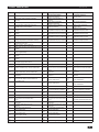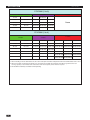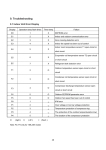
1
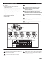
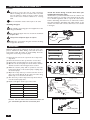
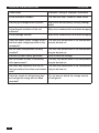
USER'S MANUAL
FREE COMBI
DC INVERTER SERIES
FC-E24AI, FC-E28AI
(outdoor units)
Please read this owner's manual carefully before operating, and keep it carefully for reference.
In line with the company’s policy of continual product improvement, the aesthetic and dimensional characteristics, technical
data and accessories of this appliance may be changed without notice.
GENERAL INFORMATION
INSTALLER
GENERAL
INFORMATION
CONTENTS
Conformity And Range
1
The Instructions Befor Use
2
Name Of The Parts
3
Technical Data
3
Outdoor Unit Working Temperature Range
3
Electrical Connections
4
Installing The Outdoor Unit
6
Bleeding
6
Maintenance
7
Installation Dimension Diagram
7
Check After Installation
8
Fault Indication
9
ALLOCATION
10
CONFORMITY AND RANGE
GENERAL INFORMATION
The air conditioner you have purchased is in conformity with the following European
Directives:
• Low Voltage 2006/95/EC
• Electromagnetic compatibility 89/336/EEC
Please read this owner's manual carefully before
operating the unit and keep it carefully for consultation.
Only use the air conditioner as instructed in this
booklet.
1
THE INSTRUCTIONS BEFORE USE
GENERAL INFORMATION
WARNING
When having a burning smell
or smoke, please turn off the power
supply and contact with the service
center .
The power supply must adopt
the special circuit that with air switch
protection and assure it has enough
capacity. The unit will be turned on or
off according to your requirement
automatically, please do not turn on
Never cut off or damage power
cables and control wires. If the power
cable and signal control wire were
damaged, change them by professional.
The appliance shall not be used by children
without supervisor.
or turn off the unit frequently, otherwise
disadvantage effect may be caused
If the abnormity still exists, the unit
to the unit.
may be damaged, and may cause
electric shock or fire.
Power must adopts the special
circuit to prevent fire.
Disconnect the power supply if
★ Never damage the electric wire or
not use the air conditioner for a long
use the electric wire which is not
time.
appointed.
Otherwise, it can cause electric
Otherwise, the accumulated dusts
Otherwise, it will cause overheating or
shock or fire.
may cause overheating or fire.
fire.
★ When cleaning, it is necessary
to stop driving and turn off the
Rated voltage of this air conditioner
220-240V~50Hz,The compressor
power supply.
will vibrate sharply if the voltage is too
Cut off power supply
Don't attempt to repair the air conditioner
by yourself.
low, resulting in damage to refrigerating
system. Electrical component are easy
to damage if the voltage is too high.
The wrong repair will lead to an electric
shock or fire, so you should contact the
Otherwise, it may cause electric
shock or damage.
Please note whether the installed
stand is firm enough or not.
service center to repair.
Don't step on the top of the outdoor unit
or place something on it.
Earthing: The unit must be reliably
earthed. The earthing cable shall
be connected to the special earthing
device in the construction.
If it is damaged, it may lead to the
As falling off the outdoor unit can be
fall of the unit and cause the injury.
dangerous.
2
NAMES OF THE PARTS
GENERAL INFORMATION
Warning
If the supply cord is damaged, it must be replaced by the manufacturer
or its service agent or a similarly qualified person in order to avoid a hazard.
Be sure to cut off the power supply before cleaning the air conditioner;
otherwise electric shock might happen.
Wetting of air conditioner may cause the risk of electric shock. Make
sure not to wash your air conditioner in any case.
Volatile liquids such as thinner or gasoline will cause damage to the
appearance of air conditioner. (Only use soft dry cloth moist cloth clean
the air conditioner cabinet).
1
Do not dispose this product as unsorted municipal waste.
Collection of such waste separately for special treatment
is necessary.
The temperature of refrigerant circuit will be high,please keep the
interconnection cable away from the copper tube.
OUTDOOR UNIT
2
No. Description
1
Air outlet grille
2
Valve
1
2
Note: the above figures are only intended to be a simple
diagram of the appliance and may not correspond to the
appearance of the units that have been purchased.
GENERAL INFORMATION
TECHNICAL DATA
Electrical data
Electricity supply
220-240V ~50
30
4.0
Fuse or air switch
Minimum power cord section
Refrigerant gas
Size and clearance
L
W
MOD
Outdoor side DB/WB(
43/26(T1)
21/24/18
-5/-6
FC-E24AI
FC-E28AI
L
950
mm
W
420
mm
H
840
mm
OUTDOOR UNIT WORKING TEMPERATURE RANGE
Maximum heating
Minimum heating
mm2
R410 A
H
Maximum cooling
Minimum cooling
V ~Hz
A
GENERAL INFORMATION
)
3
ELECTRICAL CONNECTIONS
INSTALLER
FC-E24AI:
1.Remove the handle at the right side plate of the
outdoor unit (one screw).
An all-pole disconnection switch having a contact
separation of at least 3mm in all pole should be
2. Remove the cable clamp, connect the power connection
cable with the terminal at the row of connection and fix
the connection. The fitting line distributing must be
connected in fixed wiring.
Wrong wire connection may cause malfunction of some
electric components.After fixing cable, ensure that
leads between connection to fixed point have some space.
consistent with the indoor unit. terminal of line bank.
Wiring should meet that of indoor unit.
3. Fix power connection wire by wire clamp.
The connection pipes and the connectiong wirings of
the unit A ,unit B and unit C must be corresponding to each
other respective.
4. Ensure wire has been fixed well.
5. Install the handle.
The appliance shall be installed in accordance with
national wiring regulations.
Do not install the outdoor unit where it is exposed
to the sunlight.
Handle
To unit A
YEGN Blue
Blue
Brown Black
Power
cord
To unit B
YEGN Blue
Brown
interconnection
cable
Black
To unit C
YEGN
Brown
interconnection
cable
Blue
Black
YEGN
Brown
interconnection
cable
To the power supply
Outdoor unit
Indoor unit
4
ELECTRICAL CONNECTIONS
INSTALLER
FC-E28AI:
1.Remove the handle at the right side plate of the
outdoor unit (one screw).
An all-pole disconnection switch having a contact
separation of at least 3mm in all pole should be
2. Remove the cable clamp, connect the power connection
cable with the terminal at the row of connection and fix
the connection. The fitting line distributing must be
connected in fixed wiring.
Wrong wire connection may cause malfunction of some
electric components.After fixing cable, ensure that
leads between connection to fixed point have some space.
consistent with the indoor unit. terminal of line bank.
Wiring should meet that of indoor unit.
3. Fix power connection wire by wire clamp.
The connection pipes and the connectiong wirings of
the unit A ,unit B,unit C and unit D must be corresponding to each
other respective.
4. Ensure wire has been fixed well.
5. Install the handle.
The appliance shall be installed in accordance with
national wiring regulations.
Do not install the outdoor unit where it is exposed
to the sunlight.
Handle
To unit A
YEGN Blue
Blue
Brown Black
Power
cord
To unit B
YEGN Blue
Brown
interconnection
cable
Black
To unit D
To unit C
YEGN
Brown
interconnection
cable
YEGN
Blue
Black
Brown
interconnection
cable
YEGN
Blue
Black
Brown
interconnection
cable
To the power supply
Outdoor unit
Indoor unit
HANDLING
After having removed the packaging, check that the contents are intact and complete.
USER
Handling must be done by suitably equipped qualified
technical personnel using equipment that is suitable for
the weight of the appliance.
The outdoor unit must always be kept upright.
5
INSTALLING THE OUTDOOR UNIT
INSTALLER
Location
Use bolts to secure the unit to a flat, solid floor.
When mounting the unit on a wall or the roof, make
sure the support is firmly secured so that it cannot
move in the event of intense vibrations or a strong
wind.
Do not install the outdoor unit in pits or air vents
Installing the pipes
Install the drain fitting and the drain hose (for
model with heat pump only)
Condensation is produced and flows from the outdoor unit
when the appliance is operating in the heating mode. In order
not to disturb neighbours and to respect the environment,
install a drain fitting and a drain hose to channel the condensate water. Install the drain fitting and rubber washer on the
outdoor unit chassis and connect a drain hose to it as shown
in the figure.
Use suitable connecting pipes and equipment for the
refrigerant R410A.
The refrigerant pipes must not exceed the maximum
lengths 10m.
Wrap all the refrigerant pipes and joints.
Tighten the connections using two wrenches working
in opposite directions.
INSTALLER
BLEEDING
Humid air left inside the refrigerant circuit can cause compressor malfunction. After having connected the indoor
and outdoor units, bleed the air and humidity from the
refrigerant circuit using a vacuum pump.
(1) Unscrew and remove the caps from the 2-way and 3way valves.
(2) Unscrew and remove the cap from the service valve.
(3) Connect the vacuum pump hose to the service valve.
(4) Operate the vacuum pump for 10-15 minutes until an
absolute vacuum of 10 mm Hg has been reached.
(5) With the vacuum pump still in operation, close the
low-pressure knob on the vacuum pump coupling. Stop
the vacuum pump.
(6) Open the 2-way valve by 1/4 turn and then close it
after 10 seconds. Check all the joints for leaks using
liquid soap or an electronic leak device.
(7) Turn the body of the 2-way and 3-way valves. Disconnect the vacuum pump hose.
(8) Replace and tighten all the caps on the valves.
Vacuum pump
Vacuum pump
INDOOR
UNIT
Pompa a vuoto
Refrigerant fluid direction of flow
2-way valve
3-way valve
Diameter (mm)
Twisting moment (N.m)
ø6
15-20
ø 9.52
35-40
ø 16
60-65
ø 12
45-50
ø 19
70-75
12K and 18K unit need to be installed the indoor unit
12 connection pipe with the "conversion joint"
(6) Open by 1/4 turn
(7) Turn to open fully
Service
inlet
(2) Turn
(8) Secure
(7) Turn to open fully
Valve cap
(2) Turn
(8) Secure
(2) Turn
Valve cap
(8) Secure
Connect to the
indoor unit
12K and 18K MODE:
conversion joint
6
MAINTENANCE
INSTALLER
Use suitable instruments for the refrigerant R410A.
Do not use any other refrigerant than R410A.
Do not use mineral oils to clean the unit.
INSTALLATION DIMENSION DIAGRAM
INSTALLER
The installation must be done by trained and qualified service personnel
with reliability according to this manual.
Contact service center before installation to avoid the malfunction due to
unprofessional installation.
When picking up and moving the units, you must be guided by trained and
qualified person.
Ensure that the recommended space is left around
the appliance.
7
CHECK AFTER INSTALLATION
INSTALLER
Check Items
Problems Owing to Improper Installation
Is the installation reliable?
The unit may drop, vibrate or make noises
Has the gas leakage been checked?
May cause unsatisfactory cooling (heating)
effect
Is the thermal insulation of the unit
sufficient?
May cause condensation and water dropping
Is the drainage smooth?
May cause condensation and water dropping
Does the power supply voltage accord
with the rated voltage specified on the
nameplate?
The unit may bread down or the components
may be burned out
Are the lines and pipelines correctly
installed?
The unit may bread down or the components
may be burned out
Has the unit been safely grounded?
Risk of electrical leakage
Are the models of lines in conformity
with requirements?
The unit may bread down or the components
may be burned out
The unit may bread down or the components
Are there any obstacles near the air
inlet and outlet of the indoor and outdoor may be burned out
units?
Have the length of refrigerating pipe
and refrigerant charge amount been
recorded?
8
It is not easy to decide the charge amount
of refrigerant.
FAULT INDICATION
D101
Meaning
Blink once Compressor operates
INSTALLER
D102
Blink once Air exhaust protection
frequency reducing
Twice
Compressor high pressure protection
unit stop
Three times
Air exhaust protection unit stop
Three times
Four
times
Communication malfunction unit stop
(Include indoor unit and driver
Four
times
Five
times
IPM modular protection
unit stop
Six
times
Seven
times
Phase current protection
frequncy reducing
Four
times
Phase current protection
frequncy limit
Five
times
Heating A unit anti-high
temperature frequncy reducing
Five
times
Heating A unit anti-high
temperature frequncy limit
Over current protection
unit stop
Six
times
Heating B unit anti-high
temperature frequncy reducing
Six
times
Heating B unit anti-high
temperature frequncy limit
Cooling overload unit stop
Seven
times
Heating C unit anti-high
temperature frequncy reducing
Seven
times
Heating C unit anti-high
temperature frequncy limit
Eight
times
Heating D unit anti-high
temperature frequncy reducing
Eight
times
Heating D unit anti-high
temperature frequncy limit
Phase current protection
unit stop
Fourteen
times
E2 PROM Error
unit stop
Fifteen
times
DC power supply short circuit
D104
Meaning
Blink once Outdoor ambient temp. sensor malfunction
Four
times
Twice
Nine
times
Outdoor tube temp. sensor malfunction
Outdoor air exhaust temp. sensor
malfunction
Communication malfunction with
driver (cannot receive correct data from
driver within 10s)
D105
Meaning
C unit communication malfunction
Blink once (cannot receive correct data within
3mins.)
C unit indoor middle temp. sensor
Twice
malfunction
Meaning
Three times
D106
Meaning
B unit communication malfunction
(cannot receive correct data within
3mins.)
B unit indoor middle temp. sensor
malfunction
Four
times
A unit indoor inlet pipe temp.
sensor malfunction
Four
times
B unit indoor inlet pipe temp.
sensor malfunction
Five
times
A unit indoor ambient temp.
sensor malfunction
Five
times
B unit indoor ambient temp.
sensor malfunction
Six
times
A unit modes conflict
Six
times
B unit modes conflict
Seven
times
A unit anti-freezing protection
Seven
times
B unit anti-freezing protection
A unit anti-high temp. protection
Eight
times
B unit anti-high temp. protection
D108
Meaning
D109
Meaning
Blink once
D unit communication malfunction
(cannot receive correct data within
3mins.)
Received communication data
proof test correct will flash once
D unit indoor middle temp. sensor
malfunction
D unit indoor outlet pipe temp. sensor
Three times
malfunction
Twice
C unit indoor outlet pipe temp. sensor
malfunction
Four
times
C unit indoor inlet pipe temp.
sensor malfunction
Four
times
D unit indoor inlet pipe temp.
sensor malfunction
Five
times
C unit indoor ambient temp.
sensor malfunction
Five
times
D unit indoor ambient temp.
sensor malfunction
Six
times
C unit modes conflict
Six
times
D unit modes conflict
C unit anti-freezing protection
Seven
times
D unit anti-freezing protection
C unit anti-high temp. protection
Eight
times
D unit anti-high temp. protection
Eight
times
Oil return
A unit indoor outlet pipe temp. sensor Three times B unit indoor outlet pipe temp. sensor
malfunction
malfunction
Three times
Seven
times
Nine
times
A unit communication malfunction
Blink once (cannot receive correct data within Blink once
3mins.)
A unit indoor middle temp. sensor
Twice
Twice
malfunction
Eight
times
D107
Defrosting
Compressor overload protection
unit stop
Compressor low-pressure protection
unit stop (preserved)
Thirteen
times
Three times
frequncy limit
Over current protection
frequency limit
Outdoor unit temp. sensor malfunction
or each indoor unit temp. sensor malfunction unit stop
Twice
Blink once Air exhaust protection
Three times
Ten
times
Twelve
times
Meaning
Cooling overload frequncy limit
Nine
times
Eleven
times
Cooling overload frequncy
reducing
Over current protection
frequency reducing
D103
Twice
Each indoor unit starts heating at same time
anti-high temperature protection unit stop
Each indoor unit anti-freezing protection
at same time unit stop
Eight
times
Meaning
9
ALLOCATION
INSTALLER
FC-E24AI (1 to 3)
4 models
3 models
2 models
7K+7K
9K+9K
7K+7K+7K
7K+9K
9K+12K
7K+7K+9K 7K+9K+12K 9K+9K+12K
7K+12K
12K+12K
7K+7K+12K 7K+12K+12K 9K+12K+12K
7K+18K
9K+18K
7K+7K+18K 7K+9K+18K 9K+9K+18K
12K+18K
/
7K+12K+18K 9K+12K+18K 12K+12K+18K
7K+9K+9K
9K+9K+9K
None
FC-E28AI (1 to 4)
4 models
3 models
2 models
7K+7K
9K+9K
7K+7K+7K
7K+9K
9K+12K
7K+7K+9K 7K+9K+12K 9K+9K+12K 7K+7K+7K+9K 7K+7K+9K+12K 7K+9K+9K+9K
7K+12K
12K+12K
7K+7K+12K 7K+12K+12K 9K+12K+12K 7K+7K+7K+12K 7K+9K+12K+12K 9K+9K+9K+9K
7K+18K
9K+18K
7K+7K+18K 7K+9K+18K 9K+9K+18K 7K+9K+9K+12K 9K+9K+9K+12K 9K+9K+9K+18K
12K+18K
7K+9K+9K
9K+9K+9K
7K+7K+7K+7K 7K+7K+9K+9K 7K+7K+12K+12K
7K+12K+18K 9K+12K+18K 12K+12K+18K 7K+7K+7K+18K 7K+9K+9K+18K 9K+9K+12K+18K
7K+7K+9K+18K 7K+9K+12K+18K 9K+12K+12K+18K
7K+7K+12K+18K 7K+12K+12K+18K
Note:
1. When installing 12K and 18K indoor unit, the “conversion joint” should be adopted and connected with outdoor unit’s valve.
2. When the indoor unit rated total capacity has exceeded the outdoor rated capacity that will not guarantee the real
running capacity of each indoor unit could reach their rated capacity value which is required.
3. Do not allow to install only one indoor unit for operating.
10
ENVIRONMENTAL INFORMATION
This unit contains fluorinated gases with greenhouse effect covered by the Kyoto Protocol.
Maintenance and disposal must be carried out by qualified persons only.
Refrigerant gas R410A, GWP = 1730
EXTRA REFRIGERANT CHARGE
Pursuant to Regulation EC 842/2006 on certain fluorinated greenhouse gases, in case of extra
refrigerant charge, it is compulsory to:
-
Fill in the label accompanying the unit inserting the factory quantity of refrigerant
charge (see the technical label), the extra refrigerant charge and the total charge.
Apply the label next to the technical label applied on the unit. For the split-type air
conditioner apply on the outdoor unit.