1
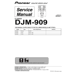
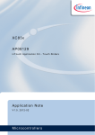
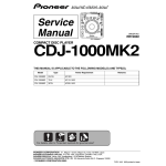
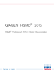
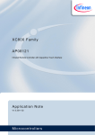
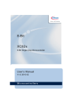
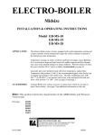
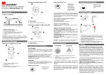
XC83x
AP08127
inTouch Application Kit - Touch Buttons
Application Note
V1.0, 2012-02
Microcontrollers
Edition 2012-02
Published by
Infineon Technologies AG
81726 Munich, Germany
© 2012 Infineon Technologies AG
All Rights Reserved.
LEGAL DISCLAIMER
THE INFORMATION GIVEN IN THIS APPLICATION NOTE IS GIVEN AS A HINT FOR THE IMPLEMENTATION
OF THE INFINEON TECHNOLOGIES COMPONENT ONLY AND SHALL NOT BE REGARDED AS ANY
DESCRIPTION OR WARRANTY OF A CERTAIN FUNCTIONALITY, CONDITION OR QUALITY OF THE
INFINEON TECHNOLOGIES COMPONENT. THE RECIPIENT OF THIS APPLICATION NOTE MUST VERIFY
ANY FUNCTION DESCRIBED HEREIN IN THE REAL APPLICATION. INFINEON TECHNOLOGIES HEREBY
DISCLAIMS ANY AND ALL WARRANTIES AND LIABILITIES OF ANY KIND (INCLUDING WITHOUT
LIMITATION WARRANTIES OF NON-INFRINGEMENT OF INTELLECTUAL PROPERTY RIGHTS OF ANY
THIRD PARTY) WITH RESPECT TO ANY AND ALL INFORMATION GIVEN IN THIS APPLICATION NOTE.
Information
For further information on technology, delivery terms and conditions and prices, please contact the nearest
Infineon Technologies Office (www.infineon.com).
Warnings
Due to technical requirements, components may contain dangerous substances. For information on the types in
question, please contact the nearest Infineon Technologies Office.
Infineon Technologies components may be used in life-support devices or systems only with the express written
approval of Infineon Technologies, if a failure of such components can reasonably be expected to cause the failure
of that life-support device or system or to affect the safety or effectiveness of that device or system. Life support
devices or systems are intended to be implanted in the human body or to support and/or maintain and sustain
and/or protect human life. If they fail, it is reasonable to assume that the health of the user or other persons may
be endangered.
AP08127
inTouch Application Kit - Touch Buttons
XC83x
Revision History: V1.0 2012-02
Previous Version(s):
Page
Subjects (major changes since last revision)
–
We Listen to Your Comments
Is there any information in this document that you feel is wrong, unclear or missing? Your feedback will help us to
continuously improve the quality of this document. Please send your proposal (including a reference to this document) to:
[email protected]
Application Note
3
V1.0, 2012-02
AP08127
inTouch Application Kit - Touch Buttons
Table of Contents
1
Introduction . . . . . . . . . . . . . . . . . . . . . . . . . . . . . . . . . . . . . . . . . . . . . . . . . . . . . . . . . . . . . . . . . . . . . 5
2
2.1
2.2
Hardware and Program Flow . . . . . . . . . . . . . . . . . . . . . . . . . . . . . . . . . . . . . . . . . . . . . . . . . . . . . . . 6
Hardware . . . . . . . . . . . . . . . . . . . . . . . . . . . . . . . . . . . . . . . . . . . . . . . . . . . . . . . . . . . . . . . . . . . . . . . 6
Program Flow . . . . . . . . . . . . . . . . . . . . . . . . . . . . . . . . . . . . . . . . . . . . . . . . . . . . . . . . . . . . . . . . . . . . 7
3
Behavior . . . . . . . . . . . . . . . . . . . . . . . . . . . . . . . . . . . . . . . . . . . . . . . . . . . . . . . . . . . . . . . . . . . . . . 11
4
4.1
U-SPY . . . . . . . . . . . . . . . . . . . . . . . . . . . . . . . . . . . . . . . . . . . . . . . . . . . . . . . . . . . . . . . . . . . . . . . . . 11
inTouch_Buttons.ini . . . . . . . . . . . . . . . . . . . . . . . . . . . . . . . . . . . . . . . . . . . . . . . . . . . . . . . . . . . . . . 11
Appendix - Schematics and Layout . . . . . . . . . . . . . . . . . . . . . . . . . . . . . . . . . . . . . . . . . . . . . . . . 14
References . . . . . . . . . . . . . . . . . . . . . . . . . . . . . . . . . . . . . . . . . . . . . . . . . . . . . . . . . . . . . . . . . . . . 17
Application Note
4
V1.0, 2012-02
AP08127
inTouch Application Kit - Touch Buttons
Introduction
1
Introduction
In today's Human-Machine Interface (HMI) designs, capacitive touch technology is now often more widely used
than traditional mechanical buttons. Capacitive touch technology is the more popular choice because it brings
flexibility, a high-level of customization, and a significant reduction in overall system cost.
The inTouch Application Kit is available to help learn about working with the advanced touch solutions provided
by Infineon. Step-by-step tutorials covers the basics of Infineon's touch solutions, while example application code
can be used to start developing new touch-related projects.
The inTouch Application Kit comprises of a mother board, supplied as a USB stick, and a number of daughter
boards. Figure 1 shows the buttons daughter board.
Among the many different touch input elements that can be designed with capacitive touch technology, the single
pad button is probably the simplest and most popular. This application note describing the buttons daughter board,
aims to highlight the ease of implementing a design with Infineon's touch solutions. Topics covered include
program flow and touch behavior.
Figure 1
inTouch Application Kit (USB Stick and Buttons board)
Application Note
5
V1.0, 2012-02
AP08127
inTouch Application Kit - Touch Buttons
Hardware and Program Flow
2
Hardware and Program Flow
This section describes the hardware used and the connections involved.
2.1
Hardware
Infineon’s XC836MT 2FRI (Figure 2) is used in this application. The XC836MT is embedded in the inTouch
Application Kit’s USB stick. For more details regarding the USB stick, please refer to AP08126: Infineon Touch
Solutions - inTouch Application Kit.
Figure 2
Infineon’s XC836MT 2FRI
The inTouch Buttons board (Figure 3) is available as a plug-in daughter board which is part of the inTouch
Application Kit.
Figure 3
Buttons daughter board
Application Note
6
V1.0, 2012-02
AP08127
inTouch Application Kit - Touch Buttons
Hardware and Program Flow
The inTouch Buttons board is a standard PCB with a piece of 2mm-thick plexiglas glued on top of the board. The
buttons on the top row are each connected to an ADC input channel of the XC836. The buttons in the bottom row
are each connected to an LEDTS input pin of the XC836. 14 indicator LEDs are connected to 2 LED column pins
(1 for each row) and 7 LED line pins of the XC836. The schematics are available in the Appendix - Schematics
and Layout.
Users can touch-and-hold (default) or tap the 14 buttons to toggle the indicator LEDs depending on the
downloaded software.
2.2
Program Flow
Infineon offers 3 solutions for capacitive touch sensing. The bottom 7 buttons, which are connected to LEDTS input
pins and hence controlled by the LEDTS module of the XC836, use the Relaxation Oscillator Topology for touch
sensing. The top 7 buttons, which are connected to ADC input pins, can use either the Charge Redistribution (CR)
or the Charge-Time Measurement (CTM) methods for touch sensing. Because two options are available, the
program name in the program flow description is taken from the name of the method (CR or CTM) used for the top
7 buttons.
For more information on the 3 touch solutions, refer to the application note AP08126: inTouch Application Kit USB Stick.
In terms of interrupts, UART interrupt has a medium priority because of the high data rate. Touch sense related
tasks are also performed with medium priority. These occur in the Time Frame interrupt after pad capacitances
have been measured. LED updates have the lowest priority. These are performed in the Time Slice interrupt
together with pad capacitance measurement. These apply to both CR (Figure 4) and CTM (Figure 5) methods.
In the CTM method, the ADC interrupt is enabled and this has the highest priority to facilitate accurate charge time
measurement.
low
Figure 4
TIME SLICE
INTERRUPT
every 384μs
medium
TIME FRAME
INTERRUPT
every 1.152ms
medium
UART INTERRUPT
LED settings,
ADC pads capacitance
measurement
Touch Sense signal
processing
Communication with
PC (send data &
receive commands)
RETI
RETI
RETI
Program Overview - CR Method
Application Note
7
V1.0, 2012-02
AP08127
inTouch Application Kit - Touch Buttons
Hardware and Program Flow
low
Figure 5
TIME SLICE
INTERRUPT
every 416μs
medium
TIME FRAME
INTERRUPT
every 1.248ms
medium
UART INTERRUPT
high
ADC
INTERRUPT
LED settings
ADC pads
capacitance
measurement
Touch Sense signal
processing
Communication with
PC (send & receive
data)
Retrieve conversion
time
RETI
RETI
RETI
RETI
Program Overview - CTM Method
The tasks performed in each interrupt service routines are further illustrated in the flowcharts which follow:
•
•
•
•
UART Interrupt (Figure 6)
– The UART module, which is part of the XC800 core, is used for full-duplex UART communication with the
PC.
Time Slice Interrupt (Figure 7)
– The LEDTS module generates this interrupt after every LED column activation where the pattern for the next
LED column is loaded into shadow registers.
Time Frame Interrupt (Figure 8)
– The LEDTS module generates this interrupt after every measurement where signal processing and touch
detection take place.
ADC Interrupt (Figure 9)
– The ADC generates this interrupt after the pad has been charged to the defined level, so that the chargetime can be measured.
Application Note
8
V1.0, 2012-02
AP08127
inTouch Application Kit - Touch Buttons
Hardware and Program Flow
Start
Receiver
Interrupt?
New
command?
Yes
Yes
Retrieve data from
buffer
No
No
Check button
selected
Transmitter
Interrupt?
Yes
Shift data out to
buffer
No
RETI
Figure 6
UART Interrupt Service Routine
Start
Figure 7
Set LED LINE
and COMPARE
values
Measure ADC
pad capacitance
RETI
Time Slice Interrupt Service Routine
Application Note
9
V1.0, 2012-02
AP08127
inTouch Application Kit - Touch Buttons
Hardware and Program Flow
Start
RETI
LEDTS pads signal
processing
ADC pads signal
processing
Toggle LED
No
Reverse bits of ADC
pad flags
Blink LEDs
PADRESULT
set?
No
Yes
LED blinking?
Yes
Blink LED
No
Off all LEDs
Yes
Send LED status to
USpy
Yes
Off LED
No
Startup over?
No
Self-calibration
PADERROR
set?
Yes
Oscilloscope
mode?
Figure 8
Yes
Yes
Send pad
Total_TSCTR & pad
Average to USpy
No
No
Do adaptive
calibration
LED Status
mode?
Time Frame Interrupt Service Routine
Start
Figure 9
Offline mode?
Clear Interrupt
Flag
Stop Timer 2
RETI
ADC Interrupt Service Routine (CTM Method)
Application Note
10
V1.0, 2012-02
AP08127
inTouch Application Kit - Touch Buttons
Behavior
3
Behavior
The inTouch Buttons board has 4 software versions:
1. The LEDs light up when respective pads are touched, using the CR method for the ADC touch pads (this is
the default software).
2. LEDs toggle when respective pads are tapped, using the CR method for the ADC touch pads.
3. The LEDs light up when respective pads are touched, using the CTM method for the ADC touch pads.
4. LEDs toggle when respective pads are tapped, using the CTM method for the ADC touch pads.
Software versions 1 and 3 use the PADFLAG output of the LEDTS ROM Library and the PADTOUCHED output
of the ADC Touch Library to implement the touch behavior as described above. Software versions 2 and 4 use the
PADRESULT outputs of the LEDTS ROM Library and the ADC Touch Library to implement the touch behavior
described above.
All software versions use the PADERROR output of the LEDTS ROM Library and the ADC Touch Library to blink
the LEDs when there is a long touch on the buttons.
4
U-SPY
For the inTouch Buttons board, one settings file, inTouch_Buttons.ini, has been configured.
4.1
inTouch_Buttons.ini
This settings file (Figure 10) is customized to allow the user to monitor the parameters of the LEDTS ROM Library
and the ADC Touch Library.
Buttons
Status Flags
Figure 10
inTouch_Buttons.ini User Interface
Application Note
11
V1.0, 2012-02
AP08127
inTouch Application Kit - Touch Buttons
U-SPY
Buttons
In this settings file, the buttons allow the user to choose the signal which the user would like to monitor. The
description of the data format for the buttons is the same as in the previous settings file. Data is transmitted in the
following format (Table 1):
Table 1
Transmit Data Format for Buttons
D0
D1
Value (hex)
08
XX
Description
I.D. number
Button number
The data received by the microcontroller will be used to determine the signals that will be transmitted to U-SPY for
display either as Status Flags (if LED Status button is selected) or on the Oscilloscope (if TSPADx or ADCPADx
is selected). If OFFLINE is selected, the microcontroller will stop sending data to U-SPY, and all touches will be
indicated by the LEDs on the board.
Status Flags
The format of the transmitted data for the status flags is as follows (Table 2):
Table 2
Transmit Data Format for Status Flags
D0
D1
D2
Value (hex)
A3
30/31
XX
Description
I.D. number
TSLED - 30
ADCLED - 31
Mask
The statuses of the LEDs received by USpy are masked before they are displayed as status flags. It is important
that the bits of a mask do not overlap with the bits of another mask. This is to ensure that status flags are not falsely
turned on. The masks used are as follows (Table 3):
Table 3
LED masks for Status Flags
LED
Number
1
2
3
4
5
6
7
Mask (hex)
01
02
04
08
10
20
40
Oscilloscope
The oscilloscope function allows the user to monitor up to 3 signals per oscilloscope at a time (Figure 11). A total
of 3 oscilloscopes are available. However, we will display only 2 signals on 1 oscilloscope in this application. The
format of the transmitted data for the oscilloscope is as follows (Table 4):
Application Note
12
V1.0, 2012-02
AP08127
inTouch Application Kit - Touch Buttons
U-SPY
Figure 11
U-SPY Oscilloscope
Table 4
Transmit Data Format for Oscilloscope
D0
D1
D2
D3
D4
D5
D6
D7
Value (hex)
A4
01
XX
XX
XX
XX
XX
XX
Description
I.D.
number
Scope
number
Signal 1
high byte
Signal 1
low byte
Signal 2
high byte
Signal 2
low byte
-
-
The signals displayed are as follows (Table 5):
Table 5
Signals Displayed on Oscilloscope
Description
Colour
Application Note
Signal 1
Signal 2
Pad Average
Pad Total_TSCTR * 2DIVISORN
Green
Pink
13
V1.0, 2012-02
Application Note
Figure 12
14
V1.0, 2012-02
inTouch Buttons Board Schematics
D
C
B
A
TP1
P$1
P$1
PAD_ROUND-15.0MM
TP2
1
P$1
1
P$1
PAD_ROUND-15.0MM
TP3
P$1
P$1
PAD_ROUND-15.0MM
18
20
16
14
12
8
6
4
2
10
TP4
P$1
P$1
AN1
AN0
AN3
AN2
AN5
AN4
AN6
2
COL1
COL2
COL0
LINE6
LINE5
LINE4
LINE3
COL5 LINE2
2
COL4 LINE1
COL3 LINE0
PAD_ROUND-15.0MM
TP5
P$1
P$1
19
17
15
13
11
9
7
5
3
1
PAD_ROUND-15.0MM
TP6
GND
P$1
P$1
PAD_ROUND-15.0MM
TP7
P$1
P$1
3
R7 1k5
R6 1k5
R5 1k5
R4 1k5
R3 1k5
R2 1k5
R1 1k5
3
PAD_ROUND-15.0MM
LED1
green
TP8
P$1
LED2
green
P$1
PAD_ROUND-15.0MM
TP9
LED3
green
P$1
P$1
PAD_ROUND-15.0MM
4
4
LED4
green
TP10
P$1
LED5
green
P$1
PAD_ROUND-15.0MM
P$1
P$1
PAD_ROUND-15.0MM
TP12
P$1
5
5
Touch Buttons
Touch Sense Application Kit
TP11
LED6
green
LED7
green
P$1
LED8
green
PAD_ROUND-15.0MM
TP13
LED9
green
P$1
P$1
PAD_ROUND-15.0MM
LED10
green
TP14
P$1
LED11
green
P$1
PAD_ROUND-15.0MM
6
6
LED12
green
LED13
green
LED14
green
D
C
B
A
Appendix - Schematics and Layout
Appendix - Schematics and Layout
AP08127
inTouch Application Kit - Touch Buttons
AP08127
inTouch Application Kit - Touch Buttons
Appendix - Schematics and Layout
15
7R
Application Note
8DEL
inTouch Buttons Board Top Layout
6R
5R
Figure 14
1DEL
9DEL
01DEL
21DEL
31DEL
41DEL
inTouch Buttons Board Component Bottom Layout
2DEL
3DEL
5DEL
6DEL
7DEL
Figure 13
V1.0, 2012-02
AP08127
inTouch Application Kit - Touch Buttons
Appendix - Schematics and Layout
Figure 15
inTouch Buttons Board Bottom Layout
Application Note
16
V1.0, 2012-02
AP08127
inTouch Application Kit - Touch Buttons
References
References
The list below provides resources that may be useful to the user.
1.
2.
3.
4.
5.
6.
7.
8.
User’s Manual - XC83x; 8-Bit Single-Chip Microcontroller
Application Note - AP08100 - Configuration for Capacitive Touch-Sense Application
Application Note - AP08110 - Design Guidelines for XC82x and XC83x Board Layout
Application Note - AP08113 - Capacitive-Touch Color Wheel Implementation
Application Note - AP08115 - Design Guidelines for Capacitive Touch-Sensing Application
Application Note - AP08121 - Infrared Remote Controller with Capacitive Touch Interface
Application Note - AP08122 - 16-Button Capacitive Touch Interface with XC836T
Application Note - AP08124 - XC82/83x Design Guidelines for Electrical Fast Transient (EFT) Protection in
Touch-Sense Applications
9. Application Note - AP08126 - Infineon Touch Solutions - inTouch Application Kit
10. Application Note - AP08128 - inTouch Application Kit - Touch Wheel
11. Application Note - AP08129 - inTouch Application Kit - Touch Sliders
12. Application Note - AP08130 - inTouch Application Kit - LED Matrix
13. Link to XC83x-Series - www.infineon.com/xc83x
14. Link to Solutions for advanced touch control - www.infineon.com/intouch
Application Note
17
V1.0, 2012-02
w w w . i n f i n e o n . c o m
Published by Infineon Technologies AG