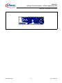
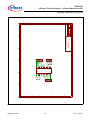
1
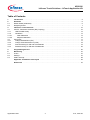
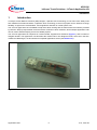
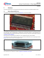
XC83x
AP08126
Infineon Touch Solutions - inTouch Application Kit
Application Note
V1.0, 2012-02
Microcontrollers
Edition 2012-02
Published by
Infineon Technologies AG
81726 Munich, Germany
© 2012 Infineon Technologies AG
All Rights Reserved.
LEGAL DISCLAIMER
THE INFORMATION GIVEN IN THIS APPLICATION NOTE IS GIVEN AS A HINT FOR THE IMPLEMENTATION
OF THE INFINEON TECHNOLOGIES COMPONENT ONLY AND SHALL NOT BE REGARDED AS ANY
DESCRIPTION OR WARRANTY OF A CERTAIN FUNCTIONALITY, CONDITION OR QUALITY OF THE
INFINEON TECHNOLOGIES COMPONENT. THE RECIPIENT OF THIS APPLICATION NOTE MUST VERIFY
ANY FUNCTION DESCRIBED HEREIN IN THE REAL APPLICATION. INFINEON TECHNOLOGIES HEREBY
DISCLAIMS ANY AND ALL WARRANTIES AND LIABILITIES OF ANY KIND (INCLUDING WITHOUT
LIMITATION WARRANTIES OF NON-INFRINGEMENT OF INTELLECTUAL PROPERTY RIGHTS OF ANY
THIRD PARTY) WITH RESPECT TO ANY AND ALL INFORMATION GIVEN IN THIS APPLICATION NOTE.
Information
For further information on technology, delivery terms and conditions and prices, please contact the nearest
Infineon Technologies Office (www.infineon.com).
Warnings
Due to technical requirements, components may contain dangerous substances. For information on the types in
question, please contact the nearest Infineon Technologies Office.
Infineon Technologies components may be used in life-support devices or systems only with the express written
approval of Infineon Technologies, if a failure of such components can reasonably be expected to cause the failure
of that life-support device or system or to affect the safety or effectiveness of that device or system. Life support
devices or systems are intended to be implanted in the human body or to support and/or maintain and sustain
and/or protect human life. If they fail, it is reasonable to assume that the health of the user or other persons may
be endangered.
AP08126
Infineon Touch Solutions - inTouch Application Kit
XC83x
Revision History: V1.0 2012-02
Previous Version(s):
Page
Subjects (major changes since last revision)
–
We Listen to Your Comments
Is there any information in this document that you feel is wrong, unclear or missing? Your feedback will help us to
continuously improve the quality of this document. Please send your proposal (including a reference to this document) to:
[email protected]
Application Note
3
V1.0, 2012-02
AP08126
Infineon Touch Solutions - inTouch Application Kit
Table of Contents
1
Introduction . . . . . . . . . . . . . . . . . . . . . . . . . . . . . . . . . . . . . . . . . . . . . . . . . . . . . . . . . . . . . . . . . . . . . 5
2
2.1
2.2
Hardware . . . . . . . . . . . . . . . . . . . . . . . . . . . . . . . . . . . . . . . . . . . . . . . . . . . . . . . . . . . . . . . . . . . . . . . 6
Mother Board (USB Stick) . . . . . . . . . . . . . . . . . . . . . . . . . . . . . . . . . . . . . . . . . . . . . . . . . . . . . . . . . . 6
Daughter Boards . . . . . . . . . . . . . . . . . . . . . . . . . . . . . . . . . . . . . . . . . . . . . . . . . . . . . . . . . . . . . . . . . . 7
3
3.1
3.1.1
3.1.2
3.1.2.1
3.1.2.2
3.2
3.2.1
3.2.2
3.2.3
3.2.4
Infineon’s Touch Solutions . . . . . . . . . . . . . . . . . . . . . . . . . . . . . . . . . . . . . . . . . . . . . . . . . . . . . . .
LEDTS - Relaxation Oscillator (RO) Topology . . . . . . . . . . . . . . . . . . . . . . . . . . . . . . . . . . . . . . . . . .
LEDTS ROM Library . . . . . . . . . . . . . . . . . . . . . . . . . . . . . . . . . . . . . . . . . . . . . . . . . . . . . . . . . . . .
Calibration . . . . . . . . . . . . . . . . . . . . . . . . . . . . . . . . . . . . . . . . . . . . . . . . . . . . . . . . . . . . . . . . . . . .
Initial Calibration . . . . . . . . . . . . . . . . . . . . . . . . . . . . . . . . . . . . . . . . . . . . . . . . . . . . . . . . . . . . .
Adaptive Calibration . . . . . . . . . . . . . . . . . . . . . . . . . . . . . . . . . . . . . . . . . . . . . . . . . . . . . . . . . . .
Using ADC . . . . . . . . . . . . . . . . . . . . . . . . . . . . . . . . . . . . . . . . . . . . . . . . . . . . . . . . . . . . . . . . . . . . .
Charge Redistribution (CR) . . . . . . . . . . . . . . . . . . . . . . . . . . . . . . . . . . . . . . . . . . . . . . . . . . . . . . .
Charge-Time Measurement (CTM) . . . . . . . . . . . . . . . . . . . . . . . . . . . . . . . . . . . . . . . . . . . . . . . . .
Data Processing for CR and CTM Methods . . . . . . . . . . . . . . . . . . . . . . . . . . . . . . . . . . . . . . . . . .
Software Library for CR and CTM Methods . . . . . . . . . . . . . . . . . . . . . . . . . . . . . . . . . . . . . . . . . . .
4
Programming Access . . . . . . . . . . . . . . . . . . . . . . . . . . . . . . . . . . . . . . . . . . . . . . . . . . . . . . . . . . . . 25
5
5.1
5.2
5.3
Monitoring . . . . . . . . . . . . . . . . . . . . . . . . . . . . . . . . . . . . . . . . . . . . . . . . . . . . . . . . . . . . . . . . . . . . .
U-SPY . . . . . . . . . . . . . . . . . . . . . . . . . . . . . . . . . . . . . . . . . . . . . . . . . . . . . . . . . . . . . . . . . . . . . . . . .
Settings . . . . . . . . . . . . . . . . . . . . . . . . . . . . . . . . . . . . . . . . . . . . . . . . . . . . . . . . . . . . . . . . . . . . . . . .
UART Interrupt . . . . . . . . . . . . . . . . . . . . . . . . . . . . . . . . . . . . . . . . . . . . . . . . . . . . . . . . . . . . . . . . . .
10
10
13
13
13
15
17
17
18
19
22
27
27
27
28
Appendix - Schematics and Layout . . . . . . . . . . . . . . . . . . . . . . . . . . . . . . . . . . . . . . . . . . . . . . . . 29
References . . . . . . . . . . . . . . . . . . . . . . . . . . . . . . . . . . . . . . . . . . . . . . . . . . . . . . . . . . . . . . . . . . . . 34
Application Note
4
V1.0, 2012-02
AP08126
Infineon Touch Solutions - inTouch Application Kit
Introduction
1
Introduction
In today's Human-Machine Interface (HMI) designs, capacitive touch technology is now often more widely used
than traditional mechanical buttons. Capacitive touch technology is the more popular choice because it brings
flexibility, a high-level of customization, and a significant reduction in overall system cost.
The inTouch Application Kit is available to help learn about working with the advanced touch solutions provided
by Infineon. Step-by-step tutorials covers the basics of Infineon's touch solutions, while example application code
can be used to start developing new touch-related projects.
The inTouch Application Kit comprises of a mother board, supplied as a USB stick (Figure 1), and a number of
daughter boards. This application note describes the mother board. The daughter boards, which are in the form
of different HMI designs, are documented in separate applications notes (see References).
Figure 1
USB Stick
Application Note
5
V1.0, 2012-02
AP08126
Infineon Touch Solutions - inTouch Application Kit
Hardware
2
Hardware
This section describes the inTouch Application Kit hardware and references the available daughter boards.
2.1
Mother Board (USB Stick)
The USB stick houses Infineon’s XC836MT-2FRI (Figure 2), an 8-bit microcontroller.
Figure 2
Infineon’s XC836MT 2FRI
The XC836MT has a dedicated LED and Touch Sense Control Unit (LEDTS) module which controls touch sensing
and drives LEDs. This is complemented by a ROM library of touch sense routines. In some applications, the
Analog-to-Digital Convertor (ADC) module is also used for touch sensing. These touch solutions will be introduced
in Infineon’s Touch Solutions.
Note: Please refer to the XC836 User’s Manual for a more detailed description of the XC836MT.
The USB stick also contains a UB2232HL chip by FTDI to provide the USB interface, and a 20-pin edge connector
(Figure 3) which offers extension to the daughter boards.
Figure 3
20-pin edge connector
The schematics for the USB stick is available in Appendix - Schematics and Layout.
Application Note
6
V1.0, 2012-02
AP08126
Infineon Touch Solutions - inTouch Application Kit
Hardware
2.2
Daughter Boards
The daughter boards that available with the inTouch Application Kit are as follows:
•
•
•
•
•
inTouch Buttons (Figure 4)
inTouch Wheel (Figure 5)
inTouch Slider and inTouch Slider II (Figure 6)
inTouch LED Matrix (Figure 7)
inTouch Adaptor (Figure 8)
– The adapter board provides the flexibility to map the pins from the edge connector to a header. This is
particularly useful for evaluating custom touch sensors.
The daughter boards are only referenced here. For more detailed documentation, please refer to the individual
application notes about each board. For the appropriate application note document numbers, please see
References.
Figure 4
inTouch Buttons Board
Application Note
7
V1.0, 2012-02
AP08126
Infineon Touch Solutions - inTouch Application Kit
Hardware
Figure 5
inTouch Wheel Board
Figure 6
inTouch Slider (right) and inTouch Slider II (left) Boards
Application Note
8
V1.0, 2012-02
AP08126
Infineon Touch Solutions - inTouch Application Kit
Hardware
Figure 7
inTouch LED Matrix Board
Figure 8
inTouch Adaptor Board
Application Note
9
V1.0, 2012-02
AP08126
Infineon Touch Solutions - inTouch Application Kit
Infineon’s Touch Solutions
3
Infineon’s Touch Solutions
Infineon offers three solutions for capacitive touch control, that differ in the method used to measure capacitance.
The solutions can be divided into two categories:
1. Using LEDTS - This solution uses the LEDTS - Relaxation Oscillator (RO) Topology.
2. Using ADC - There are 2 ADC solutions:
a) Charge Redistribution (CR)
b) Charge-Time Measurement (CTM)
These solutions are described in the following sub-sections.
3.1
LEDTS - Relaxation Oscillator (RO) Topology
In this solution that uses RO Topology for measuring capacitance, a simple circuit (Figure 9) generates
oscillations (Figure 10) on the sensor pad. The number of oscillations is then monitored in an adjustable time
window. The output frequency, fout, depends on the pad capacitance. The higher the capacitance, the lower the
frequency and the number of pulses will be. Therefore, a touch on the pad will increase the capacitance, resulting
in a lower number of pulses.
Vdd
f out
threshold
sensor pad
Figure 9
fsys
S
RO Circuit
input
threshold
pad turn
enable
pulse
count
Figure 10
1
2
3
4
5
6
Oscillations generated on sensor pad
Application Note
10
V1.0, 2012-02
AP08126
Infineon Touch Solutions - inTouch Application Kit
Infineon’s Touch Solutions
The LED and Touch Sense (LEDTS) control unit is a dedicated module which generates the oscillations and
counts them in a given time window. Figure 11 provides an overview of the touch-control blocks in the module.
For every measurement, the oscillations on the sensor pad are automatically counted and stored in TSCTRVAL.
This value is then processed by a library function residing in ROM.
Figure 11
Overview of touch-control blocks in the LEDTS
An adaptive averaging function (Figure 12) in this library generates a moving average from the measurements
and detects changes in the capacitance. The moving average eliminates any spurious peaks and troughs in the
pad frequencies to create a stable value from which the trip points can be calculated. The average is derived from
accumulating the number of oscillation counts (total TSCTR) and filtering this total TSCTR value with a first order
low-pass. This filtering is essential to detect the drop in the capacitance. All these parameters can be configured
by the user.
LPF gain
total TSCTR * LPF gain
number of pulses
Σ
total TSCTR
Low-Pass
Filter
Pad +
Averages
LowTrip
HighTrip
comp
+
Pad
Flags
-
offsets
Figure 12
Adaptive average control
Controlled by the Touch Sense State Machine (Figure 13), certain variable flags will be set or cleared when a pad
is touched, released, touched for too long or too short a time, or when touched for the correct amount of time. The
duration of touch is monitored via a pad-down counter (PDC). Figure 14 and Figure 15 illustrate the LEDTS ROM
Library signals in two scenarios (valid touch and long touch).
Application Note
11
V1.0, 2012-02
AP08126
Infineon Touch Solutions - inTouch Application Kit
Infineon’s Touch Solutions
total TSCTR
>=
LowTrip
IDLE
F R E
0 0 0
total TSCTR
<
LowTrip
ERROR
PDC = 0
error flag
cleared by
user
F R E
0 0 1
PAD
touched
F R E
1 0 0
total TSCTR
>=
LowTrip
RESULT
result flag
cleared by user
Figure 13
PDC <
ShortCount
F R E
0 1 0
PAD
released
F R E
1 1 0
PDC > ShortCount
Touch sense state machine
idle
PAD touched
PAD result
idle
PAD Average
Total TSCTR
offset
PAD Average – offset
= LowTrip
t
PDC
shortcount
PADFLAG
0
1
0
0
PADRESULT
0
0
1
0
PADERROR
0
0
0
0
Figure 14
LEDTS ROM library signals demonstrating a valid touch detected
Application Note
12
V1.0, 2012-02
AP08126
Infineon Touch Solutions - inTouch Application Kit
Infineon’s Touch Solutions
idle
PAD touched
PAD error
idle
PAD Average
Total TSCTR
offset
PAD Average – offset
= LowTrip
t
PDC
PADFLAG
0
1
0
0
0
PADRESULT
0
0
0
0
0
PADERROR
0
0
1
1
0
Figure 15
LEDTS ROM library signals demonstrating a long touch detected
3.1.1
LEDTS ROM Library
The software library for the LEDTS - Relaxation Oscillator (RO) Topology is provided in ROM. This library
contains five functions:
•
•
•
•
•
LTS_vROMLIB_Init()
– Initializes the ROM Library referred variables based on user configuration.
SET_LDLINE_CMP()
– Programs SFRs LTS_LDLINE and LTS_COMPARE for LED or/and Touch Sense, based on user-defined
input variables.
FINDTOUCHEDPAD()
– Calculates the running average for each pad turn to eliminate any spurious peaks and troughs in the pad
oscillation frequencies. This creates a stable value from which trip points can be calculated.
SpeedErrorDetection()
– Speeds up the error detection process. This is especially useful when both LED and Touch Sense functions
are enabled, where error detection can become very long.
LTS_vInitCalculation()
– Clears all flags for Touch Sense and all pad averages stored in XRAM to start all calculations afresh.
Details regarding the LEDTS ROM library can be found in the XC83x User’s Manual.
3.1.2
Calibration
The purpose of calibration is to adjust the oscillation windows to the desired sizes. The size of the oscillation
window determines the number of oscillations that can be measured for a touch pad per time frame. There are two
types of calibration:
•
•
Initial Calibration
Adaptive Calibration
3.1.2.1
Initial Calibration
Due to variations across application boards and microcontrollers, there may be a need to resize the oscillation
windows to achieve consistent performance. This is done by the initial calibration routine which is called in the
Application Note
13
V1.0, 2012-02
AP08126
Infineon Touch Solutions - inTouch Application Kit
Infineon’s Touch Solutions
initialisation stage of the application code. This routine is only executed once. The application code will run after
initial calibration completes. Figure 16 provides an overview of the routine. The user will be required to set three
parameters:
•
•
•
TS LowLimit
– the minimum number of oscillation counts (recommended value = 192)
TS HighLimit
– the maximum number of oscillation counts (recommended value = 208)
Min Compare
– the maximum oscillation window size
Start Init Calib
Get oscillation count
(TSVAL) for 1 touch
input pad
Compare TSVAL
with TS LowLimit
Larger
Reduce oscillation
window size by
incrementing
LTS_COMPARE
No
Smaller
Compare TSVAL
with TS HighLimit
Smaller
Compare current window size
(LTS_COMPARE) with max
window size (Min Compare)
End calibration for
current pad
Smaller
Complete
calibration for all
input pads?
Yes
Larger
Enlarge oscillation
window size by
decrementing
LTS_COMPARE
Figure 16
End Init Calib
Flow chart for Initial Calibration routine
Initial calibration can be enabled in DAVETM (Figure 17) and it will be automatically placed in the initialisation stage
of the generated code.
Application Note
14
V1.0, 2012-02
AP08126
Infineon Touch Solutions - inTouch Application Kit
Infineon’s Touch Solutions
Figure 17
Enabling Initial Calibration routine in DAVETM
3.1.2.2
Adaptive Calibration
The conditions of the boards’ environment may also change over time. Therefore, a need may arise to resize the
oscillation windows during run-time. The adaptive calibration routine performs this (Figure 18). In addition to the
parameter settings as required in Initial Calibration, the user will also need to configure the value for Cool-down
Period. This parameter determines the speed for the adjustment of the oscillation window size. This slow
adjustment of the oscillation windows is only performed when the respective pads are not touched.
Application Note
15
V1.0, 2012-02
AP08126
Infineon Touch Solutions - inTouch Application Kit
Infineon’s Touch Solutions
Adaptive Calibration
Enter function
Get Pad Average
value for 1 pad
Enough samples
accumulated?
Compare Average with
AverageHighLimit
Yes
Smaller
Compare Average with
AverageLowLimit
No
Smaller
Check Cool-Down
Counter if it’s time for
calibration
Yes
Larger
Reduce oscillation
window size by
incrementing
LTS_COMPARE
Compare current window size
(LTS_COMPARE) with max
window size (Min Compare)
No
Check if currently a touch
is being assessed
Larger
Enlarge oscillation
window size by
decrementing
LTS_COMPARE
Yes
Exit function
Figure 18
Flow chart for Adaptive Calibration routine
When adaptive calibration is enabled (Figure 19), the function will be available in the generated code. The user
can insert this function in the appropriate section of the application code as necessary.
Figure 19
Enabling Adaptive Calibration routine in DAVETM
Application Note
16
V1.0, 2012-02
AP08126
Infineon Touch Solutions - inTouch Application Kit
Infineon’s Touch Solutions
3.2
Using ADC
Both Charge Redistribution (CR) and Charge-Time Measurement (CTM) methods use the ADC module in the
microcontroller for touch control. The XC836MT’s ADC module allows up to a maximum of 8 channels that can be
utilised for thetouch interface. Figure 20 provides a simple illustration to explain the concept in implementing touch
using the ADC module.
Charge flow
ANx
Ssample
Spull-down
Cfinger
Cpad
CADC
Rpull-down
Touch Pad
XC800
Figure 20
Implementing touch using ADC
Before the ADC starts each sample (Spull-down is closed), the sampling capacitor (CADC) is automatically charged to
VA,REF/2 (e.g. 2.5V). During sampling (Spull-down is opened), the voltage equalizes between CADC and the touch pad
(Cpad) by charge flow. When the pad is touched, Cfinger is introduced causing an increase in the charge flow. The
remaining charge in the sampling capacitor determines the measured value.
Both of these ADC methods are easy to integrate with the LEDTS method via shared interrupts, allowing them to
be implemented together. The CR and CTM methods differ in the output for capacitance measurement, however
the data processing and detection are similar (Chapter 3.2.3).
3.2.1
Charge Redistribution (CR)
The output in the CR method is the voltage measured by the ADC. A touch on a pad will cause an increase in the
charge flow, leaving a lower amount of charge in the sampling capacitor. This translates to a lower voltage
measured by the ADC. Figure 21 provides a graphical illustration of the sampling results in the CR method.
Application Note
17
V1.0, 2012-02
AP08126
Infineon Touch Solutions - inTouch Application Kit
Infineon’s Touch Solutions
VPAD
VADC
VAref/2
Vuntouched
Vuntouched
Vtouched
Vtouched
t0
Figure 21
Tsampling
t1
t
t0
Tsampling
t1
t
Sampling result in CR Method
After capacitance has been measured, the data is processed. This is elaborated in Chapter 3.2.3.
3.2.2
Charge-Time Measurement (CTM)
In the CTM method, the ADC will keep sampling until the voltage on the touch pad reaches a pre-determined
threshold level. This can be easily implemented using the limit check boundaries and limit check control features
of the ADC module. The output in the CTM method will then be the time required to charge the touch pad to the
threshold voltage which is measured by a timer; For example, Timer 2. A touch on the pad triggers more charge
flow, resulting in a longer time taken to charge. Figure 22 provides a graphical illustration of the sampling results
in the CTM method.
Application Note
18
V1.0, 2012-02
AP08126
Infineon Touch Solutions - inTouch Application Kit
Infineon’s Touch Solutions
VPAD
Area III
t
tuntouched
ttouched
Figure 22
Sampling result in CTM Method
After capacitance has been measured, the data is processed. This is elaborated in Chapter 3.2.3.
3.2.3
Data Processing for CR and CTM Methods
The capacitance of every pad is regularly measured and the results are further processed by an enhanced
adaptive average control function (Figure 23) in a software library (Chapter 3.2.4) provided by Infineon. A moving
average is generated and changes in the capacitance are detected. The average is derived by first accumulating
the capacitance measurement results. A noise suppression block ensures that the increase in the accumulated
result per sample is capped, to filter out noise spikes. The signal is then put through a first order low-pass filter to
enable detection of changes to the signal. The hysteresis offset increases the trip-point for touch (or decreases
the offset) after a pad touch is detected. This makes the touch more stable by preventing false finger releases. All
parameters are configurable.
LPF gain
total TSCTR * LPF gain
ADC Voltage
or
Charge Time
Σ
Noise
Suppression
total TSCTR
Low-Pass
Filter
Pad +
Averages
LowTrip
HighTrip
comp
+
Pad
Flags
+/-
hysteresis
offsets
Figure 23
Enhanced adaptive average control
Flags in variables will be set or cleared by an updated touch sense state machine depending on the nature of the
finger touch. The updated touch sense state machine has two versions (Figure 24). Version B is similar to the
touch sense state machine in the ROM library (Figure 13) and it supports tapping control. Version A supports
Application Note
19
V1.0, 2012-02
AP08126
Infineon Touch Solutions - inTouch Application Kit
Infineon’s Touch Solutions
“touch&hold” control; when a pad has been touched for long enough, a respective PADTOUCHED flag will be set.
The PADTOUCHED flag will be reset when the pad has been left untouched long enough.
total TSCTR * LPF gain
>=
LowTrip
total TSCTR * LPF gain
>=
LowTrip
IDLE
Idle
E
?
total TSCTR * LPF gain
<
LowTrip
Pad
touched?
F T E
1 0 ?
F R E
0 0 0
total TSCTR * LPF gain
>=
LowTrip
F T
0 0
total TSCTR * LPF gain
<
LowTrip
PADERROR
error flag
cleared by
user
PDC init to 0xFF
and counting down
F R E
0 0 1
PDC < VT
total TSCTR * LPF gain
>=
HighTrip
PDC init to 0xFF
and counting down
Figure 24
total TSCTR * LPF gain
<
HighTrip
Pad’s been
touched
F R E
1 0 0
PDC init
to 0xFF
and
counting
down
total TSCTR * LPF gain
>=
HighTrip
PDC < VR
Pad
released?
F T E
0 1 ?
PDC = 0
Valid
Touch
F T E
1 1 ?
PADRESULT
result flag
cleared by user
F R E
0 1 0
PDC < SC
Pad’s been
released
F R E
1 1 0
PDC > SC
Set PADERROR
if PDC==0
Updated touch sense state machines versions A and B
The enhanced adaptive average control and the state machine can be executed in the time frame interrupt to
easily integrate the CR or CTM methods with the RO method using shared interrupts.
Application Note
20
V1.0, 2012-02
AP08126
Infineon Touch Solutions - inTouch Application Kit
Infineon’s Touch Solutions
Pad touched ?
Idle
Pad released ?
Valid Touch
Idle
Pad Average
Total TSCTR
small offset
offset
HighTrip
LowTrip
noise
0xFF
valid touch
PDC
valid release
0
PADFLAG
0
1
1
1
1
0
0
PADTOUCHED
0
0
1
1
1
1
0
PADERROR
0
0
0
1
1
1
1
Figure 25
Software Library version A signals demonstrating hysteresis offset and flag behaviors
Idle
Pad touched
PADRESULT
Idle
Pad Average
Total TSCTR
offset
small offset
HighTrip
LowTrip
noise
0xFF
PDC
valid touch
0
Figure 26
PADFLAG
0
1
0
0
PADRESULT
0
0
1
0
PADERROR
0
0
0
0
Software Library version B signals demonstrating hysteresis offset and valid touch detection
Application Note
21
V1.0, 2012-02
AP08126
Infineon Touch Solutions - inTouch Application Kit
Infineon’s Touch Solutions
Pad error cleared
without re -initialization
Idle
PAD Error
Pad touched
Pad released
Pad Average
Total TSCTR
offset
Idle
small offset
HighTrip
LowTrip
0xFF
PDC
error touch
0
PADFLAG
0
1
0
0
0
PADRESULT
0
0
0
0
0
PADERROR
0
0
1
1
0
Figure 27
Software Library version B signals demonstrating hysteresis offset and long touch detection
3.2.4
Software Library for CR and CTM Methods
The software library is provided as a source file called ADC_LIB.C. The library contains a total of five functions,
namely:
•
•
•
•
•
ADC_vROMLIB_Init()
– Initializes the variables used in the ADC touch software library.
ADC_vGetpadchargelevel()
– Gathers the ADC conversion results which indicate the charge level at the touch pads.
ADC_vFindtouchedpad()
– Calculates, based on the ADC conversion results, to determine whether there is a touch on a pad. This
function then updates the flags (ADC_PadX) accordingly.
ADC_vSpeedErrorDetection()
– Provides the option to speed up the error detection process.
ADC_vInitCalculation()
– Clears all flags (ADC_PadX), average and accumulated values for the pad that had an error (long) touch.
A block of user-defines is available at the beginning of the source file (Figure 28). The parameters in this block
can be altered to influence the performance of the software library. Table 1 lists down the description of these
parameters.
Application Note
22
V1.0, 2012-02
AP08126
Infineon Touch Solutions - inTouch Application Kit
Infineon’s Touch Solutions
Figure 28
Software Library User-Defines
Table 1
Description of Software Library User-Defines
Parameter
Description
Min Value
Max Value
NO_OF_PADS
Number of touch pad
inputs (ADC channels)
used in the application.
1
8
NO_OF_AD_
CONVERSIONS_
PADx
Number of times to charge 1
each touch pad in each
sample.
-
NO_OF_SAMPLES_TO_
ACCUMULATE
Number of samples to
accumulate before postdetection processing.
1
-
OFFSET_SETTING
Option for common or
individual pad offsets.
0 - for individual pad offset FFFFH
option, else any other
value will be used as the
common offset.
PADx_OFFSET
Individual pad offsets if
OFFSET_SETTING = 0.
0001H
FFFFH
SMALL_OFFSET
0001H
This value is part of the
hysteresis offset algorithm.
This value will be used in
place of the pad offset after
a pad is touched.
FFFFH
LOW_PASS_FILTER_
GAIN_FACTOR
First order low pass filter
gain factor value.
-
Application Note
1
23
V1.0, 2012-02
AP08126
Infineon Touch Solutions - inTouch Application Kit
Infineon’s Touch Solutions
Table 1
Description of Software Library User-Defines
Parameter
Description
Min Value
Max Value
VALID_TOUCH1)
FFH
When the pad-down
counter (ADC_Pdc) counts
down to this value, a valid
touch is detected.
01H
LONG_TOUCH1)
FEH
When ADC_Pdc counts
down to this value, an
invalid (long/error) touch is
detected.
00H
TRUNCATION_
FACTOR
This factor value is used to 0
scale down the
accumulated conversion
result to avoid an overflow
in the calculated average2).
-
MAX_NOISE_JUMP /
MAX_NOISE_DROP3)
The maximum noise spike 0
or dip allowed for
consecutive accumulated
conversion results. This is
to prevent false finger
release triggers.
-
1) The value of VALID_TOUCH should be set to be higher than the value of LONG_TOUCH.
2) This value is recommended to be the same as the LOW_PASS_FILTER_GAIN_FACTOR.
3) x_JUMP is used in CR method while x_DROP is used in CTM method.
Application Note
24
V1.0, 2012-02
AP08126
Infineon Touch Solutions - inTouch Application Kit
Programming Access
4
Programming Access
The USB Stick provides programming access to the microcontroller via an FTDI chip, FT2232, which acts as a
USB-to-UART bridge. Programming access is wired for half-duplex UART on pin P3.2. Flash content can be
modified with the XC800 FLOAD tool which is integrated into DAVE™ Bench (Figure 29) and is also available in
a stand-alone version.
Figure 29
Launching FLOAD from DAVETM Bench
The XC836 boot configuration does not depend on any pin status during reset. Instead, a Boot Mode Index (BMI)
configuration determines the entry to various boot modes such as User Mode, Boot-Loader (BSL) Mode and Onchip Debug (OCDS) Mode. After reset, the BMI value is read and the respective boot mode entry is automatically
executed.
The onboard microcontroller is programmed to “User Mode (Diagnostic)”. In this mode, the Boot ROM jumps to
the program memory address 0x0000 on startup to execute the user code in the Flash memory. This mode
provides Flash memory protection from external access (read/write), but with the SPD port automatically
configured to allow hot-attach. This allows the user to change the contents of the Flash memory using FLOAD
(Figure 30).
Application Note
25
V1.0, 2012-02
AP08126
Infineon Touch Solutions - inTouch Application Kit
Programming Access
Figure 30
XC800 FLOAD
Application Note
26
V1.0, 2012-02
AP08126
Infineon Touch Solutions - inTouch Application Kit
Monitoring
5
Monitoring
This section provides general information on signal monitoring via U-SPY.
5.1
U-SPY
U-SPY is a UART terminal program which allows the user to view a serial communication through a PC serial port.
Its features include transmission of a byte or group of bytes, configuration of protocol for bytes
transmission/reception and creation of dedicated control buttons, display fields, progress bars and an oscilloscope
for better visualization.
For more information, please refer to the Help menu in U-SPY.
U-SPY can be launched as a stand-alone or directly from DAVETM Bench by clicking the icon provided on the
toolbar (Figure 31).
Figure 31
Launching U-SPY from DAVETM Bench
5.2
Settings
The custom configuration and user interface for a particular task or application can be saved in the format “xxx.ini”.
This allows specific setting files to be shared among users. Figure 32 provides an example of a setting file.
Application Note
27
V1.0, 2012-02
AP08126
Infineon Touch Solutions - inTouch Application Kit
Monitoring
Figure 32
An example of a U-SPY .ini file
For the inTouch Application Kit, various .ini files have been configured to be used on different daughter boards.
The individual application notes on the daughter boards will cover in more depth regarding the specific settings for
their respective .ini files.
Serial communication is via full-duplex UART protocol at a baudrate of 57.6 kbps, using microcontroller port pins
0.7 as transmit pin and 2.7 as receive pin.
5.3
UART Interrupt
Any data transmission to or from U-SPY will trigger the UART interrupt in the XC836 microcontroller. Checks are
performed during the interrupt to determine whether data is to be transmitted or received. The data transmit or
receive process is then carried out automatically.
Application Note
28
V1.0, 2012-02
AP08126
Infineon Touch Solutions - inTouch Application Kit
Appendix - Schematics and Layout
Appendix - Schematics and Layout
Figure 33
inTouch USB Stick Schematics
Application Note
29
V1.0, 2012-02
AP08126
Infineon Touch Solutions - inTouch Application Kit
Appendix - Schematics and Layout
R6
R8
LED3
R11
R3
LED1
X1
C15
C8
R5
R4
2
GND1 C18
C3
C4
C14
C13
3
L3
R7
R13
Figure 34
IC5
IC2
IC3
LED2
4
C19
L2
L1
VDD
inTouch USB Stick Component Top Layout
R16
R15
C9
C12
C10
R2
C6
C5
1
C17
C11
R10
R1
C1
C7
C16
C2
R14
Figure 35
inTouch USB Stick Component Bottom Layout
Figure 36
inTouch USB Stick Top Layout
Application Note
30
R9 R12
V1.0, 2012-02
AP08126
Infineon Touch Solutions - inTouch Application Kit
Appendix - Schematics and Layout
Figure 37
inTouch USB Stick Bottom Layout
Application Note
31
V1.0, 2012-02
Figure 38
Application Note
32
D
C
B
A
1
1
JP2
7
6
5
4
3
2
1
2
COL5
COL4
COL3
2
20
18
16
14
12
10
8
6
4
2
AN0
AN1
AN2
AN3
AN4
AN5
AN6
COL2
COL1
COL0
LINE6
LINE5
LINE4
LINE3
COL5 LINE2
COL4 LINE1
COL3 LINE0
19
17
15
13
11
9
7
5
3
1
3
3
COL5
COL4
COL3
1
2
3
4
5
6
JP3
1
2
3
4
5
6
7
JP1
4
4
Adapter
5
Touch Sense Application Kit
5
6
6
D
C
B
A
AP08126
Infineon Touch Solutions - inTouch Application Kit
Appendix - Schematics and Layout
inTouch Adapter Schematics
V1.0, 2012-02
AP08126
Infineon Touch Solutions - inTouch Application Kit
Appendix - Schematics and Layout
Figure 39
inTouch Adapter Top Layout
Figure 40
inTouch Adapter Bottom Layout
Application Note
33
V1.0, 2012-02
AP08126
Infineon Touch Solutions - inTouch Application Kit
References
References
The list below provides resources that may be useful to the user.
1.
2.
3.
4.
5.
6.
7.
8.
User’s Manual - XC83x; 8-Bit Single-Chip Microcontroller
Application Note - AP08100 - Configuration for Capacitive Touch-Sense Application
Application Note - AP08110 - Design Guidelines for XC82x and XC83x Board Layout
Application Note - AP08113 - Capacitive-Touch Color Wheel Implementation
Application Note - AP08115 - Design Guidelines for Capacitive Touch-Sensing Application
Application Note - AP08121 - Infrared Remote Controller with Capacitive Touch Interface
Application Note - AP08122 - 16-Button Capacitive Touch Interface with XC836T
Application Note - AP08124 - XC82/83x Design Guidelines for Electrical Fast Transient (EFT) Protection in
Touch-Sense Applications
9. Application Note - AP08127 - inTouch Application Kit - Buttons
10. Application Note - AP08128 - inTouch Application Kit - Touch Wheel
11. Application Note - AP08129 - inTouch Application Kit - Touch Sliders
12. Application Note - AP08130 - inTouch Application Kit - LED Matrix
13. Link to XC83x-Series - www.infineon.com/xc83x
14. Link to Solutions for advanced touch control - www.infineon.com/intouch
Application Note
34
V1.0, 2012-02
w w w . i n f i n e o n . c o m
Published by Infineon Technologies AG