1
INFINEON
Infineon EPS User Manual
Permanent Magnet Synchronous Motor EPS User
Manual
2013
Permanent magnet synchronous motor EPS system scheme based on Infineon devices,
with high safety, high efficiency, high reliability, low cost advantages, system with power
control, the damping control, active return-to-center control, fault diagnosis, etc.
Contents
1 Introduction ...................................................................................................................................4
1.1 Infineon PMSM EPS system program graph .......................................................................5
1.2 Infineon permanent magnet synchronous motor EPS system block diagram....................6
1.3 Infineon PMSM key component BOM EPS system .............................................................6
2 Infineon EPS system features permanent magnet synchronous motor.........................................7
2.1 Infineon permanent magnet synchronous motor EPS system main parameters...............7
2.2 The main functions of Infineon permanent magnet synchronous motor EPS system .......8
2.2.1 The main functions of the system work...................................................................8
2.2.2 Protection function ..................................................................................................8
2.2.3 Communication function .........................................................................................8
3 Hardware........................................................................................................................................8
3.1 Power ..................................................................................................................................9
3.1.1 Master Power...........................................................................................................9
3.1.2 Sensor power supply..............................................................................................10
3.2 MCU ..................................................................................................................................11
3.2.1 Host microcontroller ..............................................................................................11
3.2.2 Slave MCU ..............................................................................................................12
3.3 Power Control ...................................................................................................................14
3.4 Communications ...............................................................................................................15
3.4.1 CAN communication ..............................................................................................16
3.4.2 LIN communication ................................................................................................17
3.4.3 UART communication ............................................................................................17
3.5 Signal Acquisition ..............................................................................................................18
3.5.1 Digital Signal Acquisition ........................................................................................18
3.5.2 Analog signal acquisition........................................................................................19
3.6 Interface Description.........................................................................................................21
4 Software .......................................................................................................................................23
4.1 EPS control the main program ..........................................................................................23
4.1.1 void epscontrl_init() ...............................................................................................25
4.1.2 void EPS_Cal () execution .......................................................................................26
4.1.3 Signal Sampling ......................................................................................................26
4.1.4 PID regulator ..........................................................................................................29
4.1.5 Calculation of rotor position and speed.................................................................30
4.1.6 CLARKE transform ..................................................................................................32
4.1.7 PARK Transform ......................................................................................................32
4.1.8 IPARK transform .....................................................................................................33
4.1.9 Trigonometric calculations .....................................................................................33
4.2 Assist control.....................................................................................................................33
4.3 Damping Control ...............................................................................................................34
4.4 back to the positive control ..............................................................................................35
4.5 Communications ...............................................................................................................38
4.5.1 Serial Communication ............................................................................................38
4.5.2 CAN communication...............................................................................................38
4.6 Fault Diagnosis and Protection .........................................................................................39
4.6.1 Over-current protection .........................................................................................39
4.6.2 Over-voltage Protection .........................................................................................39
4.6.3 Under-voltage protection.......................................................................................39
4.6.4 Over-Temperature Protection ................................................................................39
4.6.5 Pre-driving TLE7189QK hardware protection.........................................................40
4.7 xc836 .................................................................................................................................40
4.8 System Dual MCU software work strategy........................................................................40
5 monitors display interface............................................................................................................41
1 Introduction
Infineon is the world's largest automotive semiconductor companies in the
automotive semiconductor dominant position, such as power components,
communication, power supply, microcontroller, sensors, etc. Because the Infineon
semiconductor in auto field has high safety, efficiency advantages of low cost. The
automotive power steering system based on Infineon devices is also a lot of EPS
enterprise's first choice.
Key components of the permanent magnet synchronous motor based on Infineon
EPS solution, this system is string type EPS, the working process of the whole system can
be convenient external display monitor state, including current and steering wheel Angle,
torque, etc. At the same time, it can be adjusted system simulation speed and simulated
booster effect and back to the positive in different car speed through this interface.
System has the function of power control and damping control, active return-to-center
control function, self-diagnosis and communication function.
System control chip microcontroller using Infineon XC2336B and XC836MT,
XC2336B do host microcontroller to achieve the core of the electric power steering
control system to complete the signal acquisition and processing, communication,
power control, damping control, active return, fault diagnosis, XC836MT for the
secondary monitor microcontroller, mainly through the communication means to
communicate with the main microcontroller XC2336B, real-time monitoring host
microcontroller XC2336B, in the main microcontroller XC2336B recovery in case of
failure of the main microcontroller XC2336B, if unrecoverable circumstances can shut
down the entire system to ensure system security.
Power control, the system uses Infineon's MOSFET IPB120N04S402 and MOSFET
pre-driver TLE7189QK. IPB120N04S402 achieve sustainable working current 120A,
whose voltage is 40V, with on-resistance as small as 1.8mΩ, so the system's heat is very
small. Since TLE7189QK has three op-amps to ground, so you can easily realize the way
through the current sampling resistor, and can greatly save system cost.
System characteristics of CAN, LIN, UART communication function. High speed CAN
communication Transceiver with Infineon TLE6250G, LIN communication uses Infineon
TLE6258-2G.
System power uses Infineon's TLE42764D V50 and TLE4250-2G. TLE42764D V50 has
400mA output current capability, power supply for the system main and auxiliary
microcontroller, TLE7189QK, CAN communication, LIN communication, and UART
communications. Meanwhile, the chip has enable control, the control port can be
controlled by the ignition signal to Control the operation of the controller of work to
stop to ensure that non-working state in the automotive EPS with very low power
consumption. TLE4250-2G follower for the power, torque sensor designed for power, to
prevent short circuit caused by an external sensor system is not controllable major
security risk.
Devices based on Infineon permanent magnet synchronous motors EPS scheme
(Figure 1.1), diagram (Figure 1.2) and its key components BOM (Table 1.1) as follows:
1.1 Infineon PMSM EPS system program graph
Figure 1.1 Infineon EPS system of permanent magnet synchronous motors
1.2 Infineon permanent magnet synchronous motor EPS
system block diagram
Figure 1.2 Infineon EPS system block diagram of permanent magnet synchronous
motor
1.3 Infineon PMSM key component BOM EPS system
BOM table key components
No.
Model
Brand
Function Description
16/32 bit MCU for
system control
8-bit MCU for system
safety monitoring
Linear power supply for
the system sensor
Linear power supply for
the system sensor
LIN communication
chips
1
SAK_XC2336B_40F8OL
Infineon
2
SAK_XC836MT
Infineon
3
TLE4250-2G
Infineon
4
TLE42764D V50
Infineon
5
TLE6258-2G
Infineon
Remark
6
TLE6250G
Infineon
CAN communication
chips
Three-phase bridge
driver chip used to drive
six Mosfet
Mosfet
7
TLE7189QK
Infineon
8
IPB120N04S4-02
Infineon
9
BSP452
Infineon
10
BVS-A-R002-1.0
RHOPOINT
11
T6174
EPCOS
12
B57702M0103A001
EPCOS
13
B41695A7228Q007
EPCOS
Temperature detection
thermistor
2200uF bus capacitor
14
B82793C0513N201
EPCOS
Choker
The high-side driver
chips for bus
precharging
0.001Ω phase current
sampling resistor
21uF power supply
inductance
Table 1.1 Key components BOM
2 Infineon EPS system features permanent
magnet synchronous motor
2.1 Infineon permanent magnet synchronous motor EPS
system main parameters
• Applicable models:1.1~1.5T
• Operating Voltage Range:7~18V
• Maximum power supply input:1000W
• Controller output power: 550W(Typical),900W(Maximum)
• Motor output torque: 6N.m(Typical),9N.m(Maximum)
• Motor speed range:20~2000 r/min
• System response time: < 100ms
• Over-current protection: 62A DC(TBA)
•PWM frequency: 20 kHz
• Over Temperature Protection:135℃(Mosfet)
• Operating Temperature:-40~+105℃
2.2 The main functions of Infineon permanent magnet
synchronous motor EPS system
2.2.1 The main functions of the system work
• Assist control
• Damping Control
• Back to the positive control
• System communication functions
• System fault diagnosis function
2.2.2 Protection function
• Overvoltage Protection
• Under-voltage protection
• Over-current protection
• Over-Temperature Protection
• System Fault Protection
2.2.3 Communication function
•CAN communication
•LIN communication
•UART communication
• Other communications
3 Hardware
The system's main chips are used Infineon automotive-grade products. Mainly
includes power supply, MCU, power control, communications, hardware interface and
other parts.
3.1 Power
Power section contains a microcontroller, driver chips, communication chips power
supply part, using TLE42764D V50. Further, since the EPS system is the safety control
system, so the external sensors require a separate power supply, preventing external
short circuits of the entire system. This power supply uses the power Infineon follower
TLE4250-2G.
3.1.1 Master Power
Due to the master power supply related requirements need more 5 v power supply
parts, such as host microcontroller, slave microcontroller, MOSFET pre-driver, CAN
communication Transceiver, LIN communication Transceiver, UART communication
Transceiver, a variety of pull-up circuit circuits. Therefore, considering the drive capacity
needs, it requires a 400mA output capability of the LDO. In addition, the EPS system
power supply is connected directly to the battery, which is not working when the vehicle
is out of the open state power section, So when the vehicle does not work, want to let
the system for a minimum power state, the best way is to get the power supply and out
of sleep mode. Infineon consider these factors, added directly enable control functions
to LDO, which enable function directly connected with the engine ignition signal to
ensure that the engine operating state EPS system to begin to work. Main power supply
section (shown in Figure 3.1.1) uses TLE42764DV50 with 400mA current output
capability, which also has the enable control signal for engine ignition (IG) control.
Figure 3.1.1 TLE42764GV50 master power supply circuit
When this system needs to be started, it needs the ignition signal connected to the
12 v power supply (12 v system ignition signal for 12 v). As the demo system did not join
the ignition key control, so the signal is achieved by circuit board jump line directly
above as shown in figure 3.1.2. When using external ignition signal, it can connect the
ignition signal to the bottom through the jumper.
Figure 3.1.2 Ignition signal control circuit
3.1.2 Sensor power supply
Since the torque sensor and steering angle sensor is installed on the outside of the
controller (string above in this system), so there is the risk of sensor supply short circuit,
if the external sensor also uses the system main power supply, once the torque sensor
shorted to ground, the power will cause the chip does not work, resulting in
uncontrollable state for the entire system. Therefore, external sensors require a
separate power supply, while the external torque sensor and angle sensor is an analog
signal, you need to match with the main power system, so the selection of power
follower TLE4250-2G. Its external sensor power supply circuit is shown in Figure 3.1.2.
Figure 3.1.2 External sensor power supply
3.2 MCU
EPS is the security system, so the security and reliability requirements are relatively
high, if the system has only one microprocessor control, then the microcontroller itself,
hardware and software problems, its output state will be in a non-control state,
seriously affecting the driver's personal safety. To prevent this safety hazard, the system
uses a dual-chip, host microcontroller using XC2336B, slave microcontroller using
XC836MT.
3.2.1 Host microcontroller
Infineon16 bit microcontroller XC2336B used primarily for security control, XC2336B
for the LQFP-64 package, 80MHZ clock frequency, 320K Flash, 34K RAM, DSP functions,
38 IO ports, nine 12-bit precision AD, up to 20-channel PWM ports, an external bus
interface, two CAN nodes, four universal serial communication (as a SPI, UART, ASC, IIC
communication).
Although XC2336B is only 64 PIN package, but it has the resources which can use
three-phase motor EPS system, including analog signal sampling, the digital signal input
and output, etc. (resource allocation of the system as shown in Table 3.2.1).
NO.
XC2336B Port
Signal Interface
P5.10
P5.8
P5.4
P5.0
P5.2
SHUNT3
SHUNT2
SHUNT1
POS2
POS1
6
7
8
P5.15
P5.13
P15.0
T1MAIN
T2SUB
Temp
9
P15.4
BP
Supply voltage
sampling
P10.8
P10.9
QEPB
QEPA
Motor Resolver
Interface
(standby)
1
2
3
4
5
10
11
Signal
properties
Analog
input
Digital
signal
input
Function
Remarks
Phase current
sampling
Steering wheel
angle position
of the sampling
Torque sensor
Temperature
sampling
system
12
13
14
P10.10
P10.11
P10.15
HALLA
HALLB
HALLC
Motor
HALL
Position Sensor
Interface
15
16
P2.7
P2.8
7189_ERR2
7189_ERR1
MOSFET
pre-driver fault
feedback
P10.0
P10.1
P10.2
P10.3
P10.4
P10.5
P10.7
CPU_IH1
CPU_IH2
CPU_IH3
CPU_IL1
CPU_IL2
CPU_IL3
MainRelayOn
PWM
port
24
P2.10
GPIO0
Communication
with the XC836
25
P2.0
7189_ENA1
26
P2.2
GPU_Precharge
P2.3
P2.4
UART_TXD
UART_RXD
Enable MOSFET
pre-driven
Enable sensor
supply
Exports
communication
port
29
30
P2.5
P2.6
CAN_TXD
CAN_RXD
CAN
communication
port
31
32
P10.13
P10.14
LIN_TXD
LIN_RXD
LIN
communication
port
17
18
19
20
21
22
23
27
28
Digital
signal
output
Communic
ation
output
System
protection relay
control
Table 3.2.1 EPS system resource allocation table host microcontroller pin
3.2.2 Slave MCU
Taking into account the security of the system, and prevent failure of the main
microcontroller system caused by uncontrollable state, so the need to consider the use
of an auxiliary microcontroller used as a monitor, ensure that the system in case of
failure, the driver can still use mechanical steering system vehicle to vehicle
maintenance point for maintenance treatment.
The system’s slave microcontroller is using Infineon 8-bit high performance
microcontroller XC836MT, TSSOP-28 package. The clock frequency is 24MHZ, 0.5K of
RAM, 25 IO ports, 4 ADC channels, four PWM channels, 8K program memory space, a
universal serial communication module, support for UART, LIN, SSC, IIC. Its distribution
system port is shown in Figure 3.2.2.
NO.
XC2336B Port
Signal Interface
Function
Remarks
P0.4
7189_ERR2
MOSFET
pre-driver fault
2
P0.5
7189_ERR1
MOSFET
pre-driver fault
3
P1.3
7189_ERRn
MOSFET
pre-driver total
failure
P2.6
GPIO0
Communication
with the host
MCU port
1
4
Signal
properties
Signal
input
Output control
signal
5
6
P0.3
P0.6
6250_INH
7
P0.7
MON_MainRelayOn Power
Fault indicator
CAN
communication
transceiver
enabled
protection relay
control
8
P1.2
RESETn_836
The master
microcontroller
reset control
9
P2.3
EN1
Ignition signal
detection ports
10
P2.7
CPU_MainRelayOn
Power
protection relay
control
Figure 3.2.2 the host microcontroller of slave EPS system pin resources allocation table
3.3 Power Control
This system uses permanent magnet synchronous motor, thus driven by
three-phase bridge approach (as shown in Figure 3.3.1 and Figure 3.3.2). Since the
motor power is 500W, the maximum operating power can reach 900W, system power
supply of 12V. So it needs to reach maximum output current 75A or so. Taking into
account the safety of the motor, when the current reaches 80A (power harness 80A fuse
in series), the system is protected.
Figure 3.3.1 Power Driver Schematic
Figure 3.3.2 power drive circuit
Taking into account the current system may be operating at 80A, so the peak
current is required even greater. And it is a 12V system, the peak voltage up to 38V, so
MOSFET uses Infineon green car class IPB120N04S4-02. IPB120N04S4-02-resistance is
only 1.8mΩ, sustainable operating current can reach 120A, Rthjc is only 0.9K / W, using
TO252-3 package. Therefore, this system has the advantages of a low heat, over current
capacity, cooling capacity, etc.
MOSFET driver selection uses Infineon's TLE7189QK. Its main features are as follows:
• The PWM frequency can be to 30 KHZ
•0 ~ 100% duty cycle
• Low sensitivity of EMC and EMI
• The control input for the TTL level
• For each MOSFET of the three phase bridge control alone
• Internal hardware dead zone
• Integrated three separate precision of op-amp
• Short circuit protection, short circuit current value can be adjusted
• Over temperature warning
• Detailed fault diagnostics
• Enable and Sleep Mode
•LQFP-64 package
Because TLE7189QK internal integrates three high-precision op amps, the current
signal acquisition (as shown in figure 3.3.3) can be used in a way of MOSFET series
resistance, and then process signals through TLE7189QK internal op amp. Two of the
three signals as control signals, the third as calibration, test whether the sum of three
signals’ current is zero. Then transferred to the main control chip AD port analog to
digital conversion. This can reduce systems the failure rate of using an external op amp,
greatly improving the reliability of the system, but also reduces the system cost and PCB
area.
Figure 3.3.3 TLE7189QKand its current sampling circuit
3.4 Communications
EPS system is mainly used to communicate, including CAN, LIN, UART, etc., CAN
communication is to achieve control center communication with the body, such as the
engine speed signal, the vehicle speed signal, etc., but can also communicate via CAN
maintenance of the system, such as system upgrades, system status monitoring, and
system fault information transmission. This system provides the three communications
on hardware.
3.4.1 CAN communication
In this system, CAN communication (as shown in Figure 3.4.1.1 and Figure 3.4.1.2) is
mainly used to transmit real-time operating parameters of the motor, including system
Iq, Ia, Ib and the motor rotor angle, these few parameter transfer to the host computer,
because the CAN communication is faster, Transmit information in real time, so
debugging is very convenient.
High-speed CAN communication transceiver using Infineon's TLE6250G, support
CAN communication protocol standard ISO11898-2 which can be used for 5V and 3.3V
MCU control, but also has time to control. In the static mode, the quiescent current is
less than 10uA, -40 ° C ~ 150 ° C wide temperature operating range, coupled with
over-temperature protection, which can be used in a variety of automotive controller.
To be able to pass EMC and EMI, the CAN communication signal output, also joined
by EPCOS choke.
Figure 3.4.1.1 CAN communication diagram
Figure 3.4.1.2CAN communication PCB diagram
3.4.2 LIN communication
LIN communication in the EPS system mainly associated with the communication
between other devices, such as the communications between automotive instruments.
LIN communication of the system (as shown in Figure 3.4.2.1 and Figure 3.4.2.2) only
spare, the software does not use this feature. Transceiver using Infineon's TLE6258-2G,
supports LIN / SAE J2602/k-line1.2, 1.3 and 2.0 standards and bus wake-up function, the
transmission rate can reach 20kbit / s, which has enabled the control port, through the
enable port which can guarantee it is in a low-power mode, when the bus is idle, and the
quiescent current is less than 40uA. In protection, it has the function to prevent
short-circuit proof to ground and short circuit to a power function, and
over-temperature protection, mainly used in 12V system.
Figure 3.4.2.1 Schematic LIN communication system
Figure 3.4.2.2 LIN communication system PCB diagram
3.4.3 UART communication
Traditional UART communication has been rarely used in the automotive electronic
control unit now, but this system in order to monitor the working status of the system,
or whether the serial communication (as shown in Figure 3.4.3.1) joined them, mainly
torque sensor torque upload system signal, the steering wheel angle signal, the power
module temperature, motor current, motor rotor angle, the motor output torque, and
receives a signal sent from the monitor display, such as the vehicle speed signal and
engine speed signals. Meanwhile, Infineon microcontroller program can also be
downloaded via the serial port upgrade, which can be used in the production process
and the late upgrade.
Figure 3.4.3.1 UART communication
3.5 Signal Acquisition
Because the system uses a permanent magnet synchronous motor, you need to
collect three-phase current signal, and also had to collect the motor rotor position signal.
Motor position sensors generally use three Hall-effect sensors, and there are also
high-end products made using a rotary transformer rotor position sensor.
In addition to the motor itself signal acquisition, but also including torque sensor
signal acquisition, steering wheel angle signal acquisition, supply voltage signal
acquisition, power section temperature acquisition.
3.5.1 Digital Signal Acquisition
① HALL rotor position detection signal processing circuit (A, B, C with the same, as
shown in Figure 3.5.1.1).
Figure 3.5.1.1
② Resolver signal processing circuit (shown in Figure 3.5.1.2), this circuit is alternative,
in a system using a HALL way.
Figure 3.5.1.2
3.5.2 Analog signal acquisition
①Torque signal has two signal inputs, known as the main torque signal and sub torque
signal. The two signals are complementary signals. The voltage of the Intersection of the
two signals midpoint is 2.5V (5V power supply sensors), the hardware processing circuit
shown in Figure 3.5.2.1 and Figure 3.5.2.2 as below.
Figure 3.5.2.1 Main torque circuit
Figure 3.5.2.2 sub torque circuit
② Torque signal with the same angle signal into two signals, which has a steering wheel
angle signal and the number of turns of each coil angle signal, the hardware processing
circuit shown in Figure 3.5.2.3 and Figure 3.5.2.4.
Figure 3.5.2.3 angle signal
Figure 3.5.2.4 laps signal
③ Motor phase current vector control signal is a very important data, usually collected
two current signals, obtained by calculating the first three-phase current path. As
TLE7189QK op amp comes with a three-way, so the system in hardware made
three-phase current sampling circuit. As shown in Figure 3.5.2.5 and 3.5.2.6.
Figure 3.5.2.5 phase current op amp front
Figure 3.5.2.6 phase current op amp rear
④ Supply voltage sampling, in order to detect whether the power system working
properly, so the need for power supply voltage is sampled to ensure the system work in
8 ~ 18V. Because the system voltage 12V to 38V or more likely, while the microcontroller
AD reference voltage is 5V, taking into account the system limits the peak voltage, so the
use of 10KΩ and 1KΩ series, and then through 1KΩ resistor divider, the current sampling
circuit shown in Figure 3.5.2.7.
Figure 3.5.2.7 Power supply voltage acquisition Figure 3.5.2.8 power module
temperature acquisition
⑤Power section temperature collection, use EPCOS thermistors as temperature
sensors, this resistance can work in -40 ~ 125 ℃, the corresponding change in its
resistance to 316181 ~ 3506Ω, processing circuit shown in Figure 3.5.2.8.
3.6 Interface Description
Power steering system controller with external devices connected to the system
through the use of wire connections and plugs directly combined. Which signals
associated with motor and torque signal, and the connected motor line is directly b
connected through a wire cable. The system power supply and communication connect
y the plug.
① Power and Communications Interface U402 (shown in Figure 3.6.1 and Table 3.6.1),
the interface includes a power input interface, CAN communication interface, LIN
communication interface, UART communication interface.
Figure 3.6.1 Power Supply and Communication Interface
Pin
Function
12
Power-
11
Power+
Pin
Function
12
Power-
11
Power+
U402
9
7
Unused Ignition
information
10
8
Unused LIN
5
3
UART_RXD CANH
1
+5V
6
4
UART_TXD CANL
2
GND
Table 3.6.1 Power and Communication Interfaces
②The controller is not connected to the motor phase plug, but the PCB directly
connected (as shown in Figure 3.6.2), easy to install system connection. Using an
external plug can save PCB area, and lower cost of external plug.
Figure 3.6.2 Power output connection
③ Rotor position detection signal interface U405B and U405A torque sensor signal
interface is also directly connected to the outside (Figure 3.6.3 and Table 3.6.2), the
controller does not use the plug housing.
Figure 3.6.3 Power Output Connections
U40
5A
Pin
Function
U40
5B
Pin
Function
1
+5
V
1
X
2
GN
D
2
X
3
X
3
GN
D
4
Main
torque
4
resolve
r
5
Vice
torque
5
resolve
r
6
angle
6
HALL
A
7
Steering
wheel
revolutions
7
8
9
HALL HALL +5
B
C
V
④ Chip debug interface
Host microcontroller XC2336B debug interface shown in Figure 3.6.4, when
debugging, the SW100 all appropriated "ON" state, as shown in Figure 3.6.5.
Figure 3.6.4XC2336B DAP debug interface
Figure 3.6.5 debug mode selection
Monitoring microcontroller XC836MT debugging interface as shown in Figure 3.6.6,
XC836's debug mode supports single pin DAP Debug mode, you can save IO port
resources. In this circuit, the wire debug port is P3.2.
Figure 3.6.6 XC836MT single debug interface pin DAP
4 Software
After the System powers on (ignition signal is turned on), enter the system MCU and
its peripherals initialization, and then enter the system control initialization procedure.
System power waveform is shown in Figure 4.1.
Figure 4.1 system powers on waveform
4.1 EPS control the main program
In the file name: epscontrl.c, epscontrl.h
The function of the EPS control the main program, call the EPS control of all relevant
help, return, damping control strategy and permanent magnet synchronous motor
control.
FOC algorithm block diagram of EPS
Description: EPS of FOC algorithm are generally the same, except that the torque
current reference is from the EPS control strategy.
Main program flow chart:
4.1.1 void epscontrl_init()
Function Description:
Initialization procedure.
Call the method:
The Main () function calls a starting position, and does not perform in the future.
4.1.2 void EPS_Cal () execution
Call the method:
Each PWM cycle interrupt call at a time, in the file CCU60. C in the interrupt
(CCU60_NodeI0_INT) void CCU60_viNodeI0 (void).
Period: 100us.
Program execution time is less than 60us, as shown in figure 4.1.2.
Figure 4.1.2EPS_Cal running time
4.1.3 Signal Sampling
In the file name: sampling.c, sampling.h
Program Description: This subroutine completed the initial sampling signal zero
correction, digital format conversion. While achieving over current protection
monitoring and cut-off function.
Calling method: Each EPS_Cal () is called once the program cycle.
Variable definitions:
typedef struct{
int ia; // A phase current is sampled,62.5A -> Q15(1)
int ib; // B phase current is sampled,62.5A -> Q15(1)
int ic; //C phase current is sampled,62.5A -> Q15(1)
long ia0; // A phase corresponds to 0A current sampling offset value
long ib0; // B phase corresponds to 0A current sampling offset value
long ic0; // C phase corresponds to 0A current sampling offset value
int torque1; // Main torque corresponding sample values Torque voltage
(10%~90%)->(0~32)
long torque10; // Main torque offset value corresponding to the sampling
unsigned int TEMP; // Power zone temperature samples
unsigned int count; // Cycle Count,(60~188) Intervals were
calculated zero bias
int ready; // Initialization completion flag
}SAMPLING;
Execution Flow:
4.1.4 PID regulator
In the file name: pid.c, pid.h
Program Description: This subroutine as EPS regulator control algorithm procedures
to complete the Id, Iq current loop control
Calling method: Each EPS_Cal () is called once the program cycle.
Variable definitions:
typedef struct{ long err; // Deviation
int fdb; // Feedback
int ref; //reference
long kp; // The scaling factor
long ki; // Integrating factor
long kd; // Differential Factor
long kc; // Integral gain coefficient
long up; // proportional
long up_; // Previous cycle ratio
long ui; // Integral item
long outmax; // Maximum output limiter
long outmin; // Minimum output limiter
long saterr; // Preliminary values of output
int out; // Regulator output
}PID;
Control block diagram:
Figure1: Block diagram of PID controller with anti-windup
The formula:
Among them:
u:
PID controller output
u presat : Output before anti-saturation
Tt :
Integral time constant
Td : Derivative time constant
K c : Integral gain factor correction
4.1.5 Calculation of rotor position and speed
In the file name: electricangle.h.c, electricangle.h
Program Description: This subroutine finished calculating the position of the rotor
and speed calculation.
Calling method: Each EPS_Cal () is called once the program cycle.
Variable definitions:
typedef struct{ int preangle;// Angle of the previous cycle
int angle; // Current angle
int wheelangle;// Steering angle
int initcount; // Initialize the counter
int qepcount; // Encoder counter
int direction; // Direction of rotation
int speed;// Rotor speed 1->523rad/s = 5000 Rev/min
Machinery
int prespeed;// Rotor speed from the previous cycle
int filterspeed;// Rotor speed after low pass filtering
unsigned long time;// Two adjacent intervals code disk
int captimer; // Capture moments
int precaptimer; // Previous capture moments
int ready; // Initialization completion flag
int hall; // Hall state value
int prehall; // State of the previous cycle Hall
}ELECTANGLE;
The lower three variables hall represents three Hall-effect states. Hall State
transition position reflects the location of the rotor, so you can use these features to
determine the point of the mechanical angular position of the rotor. As shown below, a
total of six feature points:
1、 hall = 101 -> hall = 001, electang->qepcount = 6;
2、 hall = 011 -> hall = 010, electang->qepcount = 22;
3、 hall = 001 -> hall = 011, electang->qepcount = 14;
4、 hall = 110 -> hall = 100, electang->qepcount = 38;
5、 hall = 100 -> hall = 101, electang->qepcount = 46;
6、 hall = 010 -> hall = 110, electang->qepcount = 30;
Use the current and the previous cycle of the Hall to determine whether the state
after the jump position is a relatively simple way.
A mechanical angle encoder signal period is 144; reducer ratio is 22, so the motor
rotor turn around, turn the steering wheel 1/22 laps, the scope of activities of the
steering wheel three laps, so each one and a half laps. Set the maximum steering angle
of IQ15 (1), then the corresponding variable wheelangle code disc cumulative value
32768 / (33 * 144), steering wheel angle and the correspondence between the code
wheel counter is wheelangle = qepcount * 32768 / (33 * 144) = qepcount
* 6.89, rounded coefficient after wheelangle = qepcount * 6.
The motor is a 3 pole pairs, so code disk counters every increase or decrease in
144/3 = 48 values turned a power cycle. To calculate the electrical angle encoder
counter divisible by 48 using the remainder of the way to get the code disk counters
with the position of the rotor relative relationship. Then use the scale factor obtained
rotor position. IQ15 format using the electrical angle, scale factor of 32768/48 = 682.666
= 682.
Use the rotor angle values after two cycles compared to judge the rotational
direction, but pay attention at 360 degrees, 0 degrees where the hopping require special
handling.
Rotor speed calculation method: After each rotor between two adjacent time code
disc mechanical angles of 2.5 degrees can be obtained by dividing the rotor speed, finally,
the speed value pass low filter.
Angular separation between the adjacent code disc mechanical angle of 2.5 degrees,
turn the rotor disc adjacent code if more than one minute intervals, namely that the
velocity is zero; If the interval is less than 100us, is equal to 100us, because the
maximum speed of the rotor is not exceed 2.5/0.000001 = 2500000deg / s =
416666r/min.
For normalized velocity value set maximum speed of 5000r/min = 30000deg / s, that
is within the program IQ15 (1) = 32768. Conversion factor =
1deg/s/30000deg/s = 33.3333 * 10 ^ -6.
In order to more accurately calculate the turn adjacent interval between code disk,
to consider the capture time stitching.
4.1.6 CLARKE transform
In the file name: clarke.c, clarke.h
Program Description: The standard three-phase coordinate system is converted to
two-phase Cartesian coordinate system conversion formula
Calling method: Each EPS_Cal () is called once the program cycle.
The formula is:
4.1.7 PARK Transform
In the file name: park.c, park.h
Program Description: The standard two-phase stator coordinate system to the
two-phase rotor coordinate system conversion
Calling method: Each EPS_Cal () is called once the program cycle.
The formula is:
4.1.8 IPARK transform
In the file name: ipark.c, ipark.h
Program Description: PARK inverse transform
Calling method: Each EPS_Cal () is called once the program cycle.
4.1.9 Trigonometric calculations
In the file name: math_m.h,math_m.c
Program Description: Only established range 0-90 degrees in the sine function table,
the other angle cosine directly alluding to the 0-90 range, the calculated its value.
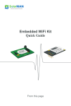
4.2 Assist control
In the file name: assisttable.c, assisttable.h
Program Description: This subroutine completed basic EPS boost function table
method to achieve different speeds, different moments practicing hand under the help.
The power curve is the reference curve (Figure 4.2), you can adjust the size according to
the driver's experience, changing the severity of practicing hand.
Calling method: Each EPS_Cal () is called once the program cycle.
Data Format: IQ15, the figure for each color represents a speed boost under the
curve, gradually decreasing from the top down.
Data in the table represent physical meaning: Let Q15 (1) = 62.5A, 62.5A current
sample voltage corresponding to Q15 (1) corresponding to the sampled value (2 ^ 15 =
32768), so the two equivalents. Characterization of the physical meaning of 20000 is,
20000/2 ^ = 20000/32768 = 15 Q15 (0.61) = 0.61 * 62.5 = 38.14
A.
Figure 4.2 assist control curve
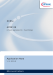
4.3 Damping Control
In the file name: damp.c,damp.h
Program Description: This subroutine completed damping control function under
different speed.
Calling method: Each EPS_Cal () is called once the program cycle.
Damping current I = - damping * motor speed
Damping control coefficient map:
The picture shows the reference debug curve (Figure 4.3), each point can vary with
different models for debugging. The main purpose is to solve the car at high speed when
the damping is too small and the steering system center unstable. So low active damping
is small and high-speed large. Debugging personnel can be resized based on the actual
situation.
Data in the table represent physical meaning: Let Q15 (1) represents the maximum
damping factor, the characterization of the physical meaning 20000 is 20000/2 ^ 15 =
20000/32768 = Q15 (0.61), 0.61 represents the maximum damping.
Figure 4.3 damping control curve
4.4 back to the positive control
In the file name: return.c,return.h
Program Description: This subroutine completed the medium speed (14 ~ 69km / h)
under the initiative back to the positive control function
Calling method: called one time when the back is marked as 1.
Variable definitions:
typedef struct{ int ang; // steering wheel Angle
unsigned int ve; // The speed of the car
int speed; // The rotor speed
int out; // Back to the positive voltage
int angintegr;// Integral item
int torq; // The steering wheel torque
int start; // Start back flag
unsigned int keeploosen; //loosen time
} RET;
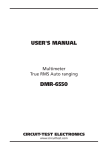
Correction coefficient of speed control
Adjust the return-to-center control curve (as shown in figure 4.4.1) can control the
correction speed, maximum IQ15 (1) (32768) represents the fastest speed. Adjusting
Speed back to different speed according to the driving experience, let the
return-to-center performance to achieve optimal state.
Back to positive voltage = correction speed coefficient (KP * ang + ∑ ki *ang);
Through the formula to adjust back to positive voltage;
PID debugging general steps:
a. Determine the proportional gain P
Determine the proportional gain P, the first to remove the PID integral and
differential terms, generally let Ti = 0, Td = 0 (see specific instructions PID parameter
setting), the PID for the pure proportional control. Input is set to the 60% to 70% of the
maximum allowed by the system, gradually increase the proportional gain P starting
from 0, until the system oscillates; another turn, from the proportional gain P gradually
decreases until the oscillation disappears, recording the proportional gain P at this point,
set the PID proportional gain P is the current value of 60% to 70%. Proportional gain P
commissioning completed.
b. Determine the integration time constant Ti
Proportional gain P is determined, set a larger initial value of the integral time
constant Ti, and then gradually decreases Ti, until the system oscillates, after which, in
turn, gradually increasing Ti, until the system oscillations disappear. Record the Ti, set
the PID integral time constant Ti is the current value of 150% ~ 180%. Integral time
constant Ti commissioning completed.
c. Determine the derivative time constant Td
Integral time constant Td is generally not set to 0. To set up, the same way as the
method of setting P and Ti, taking 30% of the time when it does not oscillate.
d. System load, load the FBI, and then fine-tune the PID parameters until satisfied.
Data in the table represent physical meaning: Let Q15 (1) represents the fastest
speed, the characterization of the physical meaning of 30000 is 30000/2 ^ 15 =
30000/32768 = Q15 (0.91) which represents the fastest speed of 0.91 times.
Figure 4.4.1 back to the positive control curve
Flowchart:
Figure 4.2.2 back to the positive control flow
Back to the positive debugging method: proportional kp decided to return a positive
response rate, the greater the proportion of items, return faster, but easy to overshoot, if
there is overshoot, then transfer a small proportional term; integral term decided to
return to a positive residual angle , if a return is insufficient, increase the integral
coefficient ki.
4.5 Communications
4.5.1 Serial Communication
In the file name: main.c
Program Description: This code implements the function of communication with the
host computer.
Call the method: the main program loop waits, sending and receiving data when
idle.
Communication protocol:
Receiving protocol:
Packet header the checksum End of Frame
CMD3
INT16
INT16
* / / receives vehicle speed information.
Parity (XOR): the checksum = Packet ^ character 3
Transmission protocol:
Packet header the checksum End of Frame
55
INT16
INT16
AA
Parity (XOR): Checksum = Data 0 ^Data 1 ^ ....... ^ 8 data.
4.5.2 CAN communication
Interface Description
utility.c the two functions.
void vCAN_Transfer (unsigned char * p)
This function is used to transmit CAN data
void vCAN_Receive (CAN_PACKAGE_PTR CanPackagePtr)
This function is used for data reception.
This function uses the CAN structure is:
typedef struct
{
unsigned long u32CAN_ID;
unsigned char u8CAN_LEN;
unsigned int u16CAN_DATA[4];
} CAN_PACKAGE;
u32CAN_ID; // CAN ID of the packet
u8CAN_LEN; // CAN data packet length
unsigned int u16CAN_DATA[4]; // Packet storage array
4.6 Fault Diagnosis and Protection
System mainly includes Over-current protection, Over-voltage Protection,
Under-voltage protection, Over-Temperature Protection, pre-drive TLE7189QK hardware
protection.
4.6.1 Over-current protection
System is used for controlling the phase current to the motor, but the acquisition of
the two-phase current, the third phase current can be calculated. Therefore, in the
acquisition of two-phase current, once one phase current exceeds 62A, it will disconnect
the power section supply (relay disconnected) to guarantee fast shutdown of the system
and timely current protection in order to protect the motor effect.
4.6.2 Over-voltage Protection
Since the system supply voltage may be unstable, especially in the case of magneto
unstable, its supply voltage can reach more than 38V. Therefore, the system requires
real-time monitoring system voltage, and makes the appropriate protection. By
monitoring the system input voltage, when the system voltage reaches 18V or more, it
will disconnect the power section supply (relay disconnected) to protect the pre-drive
TLE7189QK and MOSFET.
4.6.3 Under-voltage protection
EPS working at large angles as the turn, which requires relatively large current, can
reach more than 60A. If the voltage is low, the output is still such a large current, and
then it will seriously shorten the battery life. Therefore, when the voltage is low, it also
needs protection. So it will disconnect the power supply section (relay disconnected)
to protect the system battery.
4.6.4 Over-Temperature Protection
Vehicles entering the mountain drive, it takes a long period of sustained turn. At this
time EPS system continued working current is large. The power part of the EPS system
therefore severe fever, because it is not timely cooling, the temperature will cause the
power section increasing rapidly. If you do not monitor and protection, when the
temperature rises to a certain time it will affect the system performance, severe burning
power devices. Therefore, the system monitors the temperature reaches 135 ℃ bottom
MOSFET, it will disconnect the power section supply (relay disconnected) to protect the
pre-drive TLE7189QK, MOSFET and its surrounding parts.
4.6.5 Pre-driving TLE7189QK hardware protection
Because software protection rapid response is limited, in addition to software
protection system, another TLE7189QK inherently fast over-current, over-voltage,
over-temperature protection automatic hardware, software and hardware can be
achieved simultaneously monitor dual protection.
4.7 xc836
XC836 communication with XC2336B, primarily achieve through an IO port. SCM
function is currently reading xc2336B relay control signal, 7189_ERRn, 7189_ERR1, and
7189_ERR2. Then the LED display four signal levels. XC836 does not participate in the
specific power control, damping control, back to the positive control and communication
functions with the host computer, and its main function is to monitor the master chip
XC2336B, and is responsible for controlling TLE7189QK the 7189EN, and non-normal
working hours in XC2336B be reset and the alarm function.
4.8 System Dual MCU software work strategy
The master system implemented by the XC2336B assist control, damping control,
back to the positive control, system status information is uploaded, the control
parameters received and so on. And sub controlled by the XC836 to achieve control
XC2336B's work, mainly through the IO communication judging XC2336B whether
working properly, once XC233B has not XC836 communications, is considered the master
MCU to operate normally, need to be reset, if still does not work after trying to reset,
you need to completely close the whole controller's power section and alarm the user to
do maintenance.The specific process is as follows:
1, after powers on, XC2336 control relay on (CpuMainRelayOn = 0);
2, XC836 detects CpuMainRelayOn, when it is "0", McuMainRelayOn = 0;
3, the 7189en of XC836 as outputs. Enable the 7189EN of TLE7189QK.
4, XC2336’s 7189en pin set as input. XC2336 detection 7189en is high, TLE7189QK
start normal operation by INH enabled.
6, when MCU found 7189 ERR pin in fault state, close the 7189EN of TLE7189QK.
7, XC2336B found EN is "0", close off INH and the relay.
Communicate with each other work process is as follows:
1, in normal operation, XC2336B periodic inverted status of GPIO.
2, if the XC836 found XC2336B doesn’t normal turn over within a certain time, then
close off the 7189EN of TLE7189QK.
3, test for XC2336B reset.
4, if 3 consecutive reset XC2336B, XC2336B, it still does not work, then will close the
7189EN of TLE7189QK, alarm and display.
After XC2336B powers on, PORT2 = 0X0x0004, PORT10 = 0x0080
The process of XC2336B handshake with the XC836 is
XC2336B
XC836
1 An open relay is enabled (P10.7 = 0) ----------> Waiting XC2336B open relay enable
2 GPIO set 1
open TLE6250, enable TLE7189QK
3 Wait XC836 enable TLE7189QK
<---------- waiting GPIO = 1
4 Enable TLE7189QK (INHn = 1)
----------> Waiting XC2336B the GPIO is set 0
5 GPIO set 0
----------> begin monitoring.
5 monitors display interface
In order to intuitive monitoring in the system working condition, the system uses an
external monitor for visual display. It mainly consists of torque signal of the torque
sensor system, steering wheel angle signal, the power module temperature, motor
current, motor rotor angle, the motor output torque. The interface can be adjusted
directly on the analog speed signal (Figure 5.1 and Figure 5.2)
Figure 5.1 digital display interface
Figure 5.2 shows the interface