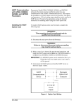
1
GE
Sensing & Inspection Technologies
Flow
Communications Options
User’s Guide
916-115_5 Rev. A
February 2009
GE
Sensing & Inspection Technologies
Communications Options
User’s Guide
916-115_5 Rev. A
February 2009
GESensingInspection.com
©2009 General Electric Company. All rights reserved.
Technical content subject to change without notice.
[no content intended for this page - proceed to next page]
ii
Contents
Chapter 1. Modbus Communications
1.1
Introduction . . . . . . . . . . . . . . . . . . . . . . . . . . . . . . . . . . . . . . . . . . . . . . . . . . . . . . . . . . . . . . . . . . . . . . . . . . . . . . . . . . . . . . . . . . . . 1
1.2
Installing the MODBUS Option Card . . . . . . . . . . . . . . . . . . . . . . . . . . . . . . . . . . . . . . . . . . . . . . . . . . . . . . . . . . . . . . . . . . . . . 2
1.3
Setting Up MODBUS Communications . . . . . . . . . . . . . . . . . . . . . . . . . . . . . . . . . . . . . . . . . . . . . . . . . . . . . . . . . . . . . . . . . . . 2
1.4
MODBUS Register Map. . . . . . . . . . . . . . . . . . . . . . . . . . . . . . . . . . . . . . . . . . . . . . . . . . . . . . . . . . . . . . . . . . . . . . . . . . . . . . . . . . 4
1.4.1
1.5
Notes: . . . . . . . . . . . . . . . . . . . . . . . . . . . . . . . . . . . . . . . . . . . . . . . . . . . . . . . . . . . . . . . . . . . . . . . . . . . . . . . . . . . . . . . . . . 8
Swapping the Floating Point . . . . . . . . . . . . . . . . . . . . . . . . . . . . . . . . . . . . . . . . . . . . . . . . . . . . . . . . . . . . . . . . . . . . . . . . . . .10
Chapter 2. Modbus Over Ethernet Communications 1
2.1
Introduction . . . . . . . . . . . . . . . . . . . . . . . . . . . . . . . . . . . . . . . . . . . . . . . . . . . . . . . . . . . . . . . . . . . . . . . . . . . . . . . . . . . . . . . . . . .15
2.2
Setup . . . . . . . . . . . . . . . . . . . . . . . . . . . . . . . . . . . . . . . . . . . . . . . . . . . . . . . . . . . . . . . . . . . . . . . . . . . . . . . . . . . . . . . . . . . . . . . . .16
2.2.1
Finding the Assigned IP Address . . . . . . . . . . . . . . . . . . . . . . . . . . . . . . . . . . . . . . . . . . . . . . . . . . . . . . . . . . . . . . . .16
2.2.2
Changing the Password . . . . . . . . . . . . . . . . . . . . . . . . . . . . . . . . . . . . . . . . . . . . . . . . . . . . . . . . . . . . . . . . . . . . . . . .17
2.2.3
Changing IP Parameters . . . . . . . . . . . . . . . . . . . . . . . . . . . . . . . . . . . . . . . . . . . . . . . . . . . . . . . . . . . . . . . . . . . . . . .18
Chapter 3. Modbus Over Ethernet Communications 2
3.1
Introduction . . . . . . . . . . . . . . . . . . . . . . . . . . . . . . . . . . . . . . . . . . . . . . . . . . . . . . . . . . . . . . . . . . . . . . . . . . . . . . . . . . . . . . . . . . .21
3.2
Setup . . . . . . . . . . . . . . . . . . . . . . . . . . . . . . . . . . . . . . . . . . . . . . . . . . . . . . . . . . . . . . . . . . . . . . . . . . . . . . . . . . . . . . . . . . . . . . . . .22
3.2.1
Downloading the Digi Device Discovery Program . . . . . . . . . . . . . . . . . . . . . . . . . . . . . . . . . . . . . . . . . . . . . . . .22
3.2.2
Module LED Behaviors . . . . . . . . . . . . . . . . . . . . . . . . . . . . . . . . . . . . . . . . . . . . . . . . . . . . . . . . . . . . . . . . . . . . . . . . .22
3.2.3
Default Parameters . . . . . . . . . . . . . . . . . . . . . . . . . . . . . . . . . . . . . . . . . . . . . . . . . . . . . . . . . . . . . . . . . . . . . . . . . . . .22
3.2.4
Finding the Assigned IP Address . . . . . . . . . . . . . . . . . . . . . . . . . . . . . . . . . . . . . . . . . . . . . . . . . . . . . . . . . . . . . . . .23
3.2.5
Changing IP Parameters . . . . . . . . . . . . . . . . . . . . . . . . . . . . . . . . . . . . . . . . . . . . . . . . . . . . . . . . . . . . . . . . . . . . . . .24
3.2.6
Changing Modbus/TCP Network Parameters . . . . . . . . . . . . . . . . . . . . . . . . . . . . . . . . . . . . . . . . . . . . . . . . . . . .25
3.2.7
Changing User’s Information . . . . . . . . . . . . . . . . . . . . . . . . . . . . . . . . . . . . . . . . . . . . . . . . . . . . . . . . . . . . . . . . . . .26
Chapter 4. Ethernet Only Communications
4.1
Introduction . . . . . . . . . . . . . . . . . . . . . . . . . . . . . . . . . . . . . . . . . . . . . . . . . . . . . . . . . . . . . . . . . . . . . . . . . . . . . . . . . . . . . . . . . . .29
4.2
Setup . . . . . . . . . . . . . . . . . . . . . . . . . . . . . . . . . . . . . . . . . . . . . . . . . . . . . . . . . . . . . . . . . . . . . . . . . . . . . . . . . . . . . . . . . . . . . . . . .30
4.2.1
Downloading the Digi Device Discovery Program . . . . . . . . . . . . . . . . . . . . . . . . . . . . . . . . . . . . . . . . . . . . . . . .30
4.2.2
Module LED Behaviors . . . . . . . . . . . . . . . . . . . . . . . . . . . . . . . . . . . . . . . . . . . . . . . . . . . . . . . . . . . . . . . . . . . . . . . . .30
4.2.3
Default Parameters . . . . . . . . . . . . . . . . . . . . . . . . . . . . . . . . . . . . . . . . . . . . . . . . . . . . . . . . . . . . . . . . . . . . . . . . . . . .30
4.2.4
Finding the Assigned IP Address . . . . . . . . . . . . . . . . . . . . . . . . . . . . . . . . . . . . . . . . . . . . . . . . . . . . . . . . . . . . . . . .31
4.2.5
Changing IP Parameters . . . . . . . . . . . . . . . . . . . . . . . . . . . . . . . . . . . . . . . . . . . . . . . . . . . . . . . . . . . . . . . . . . . . . . .32
4.2.6
Changing User’s Information . . . . . . . . . . . . . . . . . . . . . . . . . . . . . . . . . . . . . . . . . . . . . . . . . . . . . . . . . . . . . . . . . . .33
Communications Options User’s Guide
iii
Contents
Chapter 5. Modbus Over WI-FI Communications
5.1
Introduction. . . . . . . . . . . . . . . . . . . . . . . . . . . . . . . . . . . . . . . . . . . . . . . . . . . . . . . . . . . . . . . . . . . . . . . . . . . . . . . . . . . . . . . . . . .35
5.2
WI-FI Components . . . . . . . . . . . . . . . . . . . . . . . . . . . . . . . . . . . . . . . . . . . . . . . . . . . . . . . . . . . . . . . . . . . . . . . . . . . . . . . . . . . .35
5.3
Setup . . . . . . . . . . . . . . . . . . . . . . . . . . . . . . . . . . . . . . . . . . . . . . . . . . . . . . . . . . . . . . . . . . . . . . . . . . . . . . . . . . . . . . . . . . . . . . . . .37
5.4
5.3.1
Downloading the Digi Device Discovery Program. . . . . . . . . . . . . . . . . . . . . . . . . . . . . . . . . . . . . . . . . . . . . . . .37
5.3.2
Module LED Behaviors . . . . . . . . . . . . . . . . . . . . . . . . . . . . . . . . . . . . . . . . . . . . . . . . . . . . . . . . . . . . . . . . . . . . . . . . .37
5.3.3
Default Parameters . . . . . . . . . . . . . . . . . . . . . . . . . . . . . . . . . . . . . . . . . . . . . . . . . . . . . . . . . . . . . . . . . . . . . . . . . . . .37
5.3.4
Finding the Assigned IP Address . . . . . . . . . . . . . . . . . . . . . . . . . . . . . . . . . . . . . . . . . . . . . . . . . . . . . . . . . . . . . . . .38
5.3.5
Changing IP Parameters . . . . . . . . . . . . . . . . . . . . . . . . . . . . . . . . . . . . . . . . . . . . . . . . . . . . . . . . . . . . . . . . . . . . . . .39
5.3.6
Changing Modbus/TCP Network Parameters . . . . . . . . . . . . . . . . . . . . . . . . . . . . . . . . . . . . . . . . . . . . . . . . . . . .40
5.3.7
Changing User’s Information . . . . . . . . . . . . . . . . . . . . . . . . . . . . . . . . . . . . . . . . . . . . . . . . . . . . . . . . . . . . . . . . . . .41
Tips for Improving Wireless Data Communications. . . . . . . . . . . . . . . . . . . . . . . . . . . . . . . . . . . . . . . . . . . . . . . . . . . . . .43
Chapter 6. WI-FI Only Communications
6.1
Introduction. . . . . . . . . . . . . . . . . . . . . . . . . . . . . . . . . . . . . . . . . . . . . . . . . . . . . . . . . . . . . . . . . . . . . . . . . . . . . . . . . . . . . . . . . . .45
6.2
WI-FI Components . . . . . . . . . . . . . . . . . . . . . . . . . . . . . . . . . . . . . . . . . . . . . . . . . . . . . . . . . . . . . . . . . . . . . . . . . . . . . . . . . . . .45
6.3
Setup . . . . . . . . . . . . . . . . . . . . . . . . . . . . . . . . . . . . . . . . . . . . . . . . . . . . . . . . . . . . . . . . . . . . . . . . . . . . . . . . . . . . . . . . . . . . . . . . .47
6.4
6.3.1
Downloading the Digi Device Discovery Program. . . . . . . . . . . . . . . . . . . . . . . . . . . . . . . . . . . . . . . . . . . . . . . .47
6.3.2
Module LED Behaviors . . . . . . . . . . . . . . . . . . . . . . . . . . . . . . . . . . . . . . . . . . . . . . . . . . . . . . . . . . . . . . . . . . . . . . . . .47
6.3.3
Default Parameters . . . . . . . . . . . . . . . . . . . . . . . . . . . . . . . . . . . . . . . . . . . . . . . . . . . . . . . . . . . . . . . . . . . . . . . . . . . .47
6.3.4
Finding the Assigned IP Address . . . . . . . . . . . . . . . . . . . . . . . . . . . . . . . . . . . . . . . . . . . . . . . . . . . . . . . . . . . . . . . .48
6.3.5
Changing IP Parameters . . . . . . . . . . . . . . . . . . . . . . . . . . . . . . . . . . . . . . . . . . . . . . . . . . . . . . . . . . . . . . . . . . . . . . .49
6.3.6
Changing User’s Information . . . . . . . . . . . . . . . . . . . . . . . . . . . . . . . . . . . . . . . . . . . . . . . . . . . . . . . . . . . . . . . . . . .50
Tips for Improving Wireless Data Communications. . . . . . . . . . . . . . . . . . . . . . . . . . . . . . . . . . . . . . . . . . . . . . . . . . . . . .52
Chapter 7. Foundation Fieldbus Communications
7.1
Optional Measurements . . . . . . . . . . . . . . . . . . . . . . . . . . . . . . . . . . . . . . . . . . . . . . . . . . . . . . . . . . . . . . . . . . . . . . . . . . . . . . .53
7.2
Configuration Utility Setup . . . . . . . . . . . . . . . . . . . . . . . . . . . . . . . . . . . . . . . . . . . . . . . . . . . . . . . . . . . . . . . . . . . . . . . . . . . . .54
7.3
Selecting the Desired Measurements . . . . . . . . . . . . . . . . . . . . . . . . . . . . . . . . . . . . . . . . . . . . . . . . . . . . . . . . . . . . . . . . . . .54
7.4
Selecting Units for AI Blocks. . . . . . . . . . . . . . . . . . . . . . . . . . . . . . . . . . . . . . . . . . . . . . . . . . . . . . . . . . . . . . . . . . . . . . . . . . . .56
7.5
Resetting Instrument Totalizers . . . . . . . . . . . . . . . . . . . . . . . . . . . . . . . . . . . . . . . . . . . . . . . . . . . . . . . . . . . . . . . . . . . . . . . .57
7.6
Function Block Application. . . . . . . . . . . . . . . . . . . . . . . . . . . . . . . . . . . . . . . . . . . . . . . . . . . . . . . . . . . . . . . . . . . . . . . . . . . . .58
Chapter 8. HART Communications
8.1
Introduction. . . . . . . . . . . . . . . . . . . . . . . . . . . . . . . . . . . . . . . . . . . . . . . . . . . . . . . . . . . . . . . . . . . . . . . . . . . . . . . . . . . . . . . . . . .59
8.2
Installing the HART Option Card . . . . . . . . . . . . . . . . . . . . . . . . . . . . . . . . . . . . . . . . . . . . . . . . . . . . . . . . . . . . . . . . . . . . . . . .59
8.3
Flowmeter Software Setup. . . . . . . . . . . . . . . . . . . . . . . . . . . . . . . . . . . . . . . . . . . . . . . . . . . . . . . . . . . . . . . . . . . . . . . . . . . . .60
8.4
Using the HART Interface . . . . . . . . . . . . . . . . . . . . . . . . . . . . . . . . . . . . . . . . . . . . . . . . . . . . . . . . . . . . . . . . . . . . . . . . . . . . . .61
8.5
iv
8.4.1
Unit Types . . . . . . . . . . . . . . . . . . . . . . . . . . . . . . . . . . . . . . . . . . . . . . . . . . . . . . . . . . . . . . . . . . . . . . . . . . . . . . . . . . . . .61
8.4.2
HART Functions. . . . . . . . . . . . . . . . . . . . . . . . . . . . . . . . . . . . . . . . . . . . . . . . . . . . . . . . . . . . . . . . . . . . . . . . . . . . . . . .62
List of Programmable Variables . . . . . . . . . . . . . . . . . . . . . . . . . . . . . . . . . . . . . . . . . . . . . . . . . . . . . . . . . . . . . . . . . . . . . . . .62
Communications Options User’s Guide
Preface
Information Paragraphs
•
Note paragraphs provide information that provides a deeper understanding of the situation, but is not essential to
the proper completion of the instructions.
•
Important paragraphs provide information that emphasizes instructions that are essential to proper setup of the
equipment. Failure to follow these instructions carefully may cause unreliable performance.
•
Caution! paragraphs provide information that alerts the operator to a hazardous situation that can cause damage to
property or equipment.
•
Warning! paragraphs provide information that alerts the operator to a hazardous situation that can cause injury to
personnel. Cautionary information is also included, when applicable.
Safety Issues
WARNING! It is the responsibility of the user to make sure all local, county, state and national codes,
regulations, rules and laws related to safety and safe operating conditions are met for each
installation.
Auxiliary Equipment
Local Safety Standards
The user must make sure that he operates all auxiliary equipment in accordance with local codes, standards,
regulations, or laws applicable to safety.
Working Area
WARNING! Auxiliary equipment may have both manual and automatic modes of operation. As equipment
can move suddenly and without warning, do not enter the work cell of this equipment during
automatic operation, and do not enter the work envelope of this equipment during manual
operation. If you do, serious injury can result.
WARNING! Make sure that power to the auxiliary equipment is turned OFF and locked out before you
perform maintenance procedures on the equipment.
Communications Options User’s Guide
v
Preface
Qualification of Personnel
Make sure that all personnel have manufacturer-approved training applicable to the auxiliary equipment.
Personal Safety Equipment
Make sure that operators and maintenance personnel have all safety equipment applicable to the auxiliary equipment.
Examples include safety glasses, protective headgear, safety shoes, etc.
Unauthorized Operation
Make sure that unauthorized personnel cannot gain access to the operation of the equipment.
vi
Communications Options User’s Guide
Chapter 1. Modbus Communications
Chapter 1.
Modbus Communications
1.1 Introduction
Your flowmeter hardware and software (GC3E.MBS) have been modified to provide improved MODBUS
communications. The MODBUS option card provides an RS485 interface with a host system, while the main circuit
board continues to support RS232 communications for use with a PC running PanaView™ software.
Note: PanaView™ does not support Modbus.
To properly set up the instrument, use this addendum along with the standard flowmeter User’s Manual. This document
shows how to install the MODBUS option card and how to program the modified flowmeter to access this special
feature.
When equipped with the optional MODBUS output card, the flow transmitter can send flow data and diagnostic
information to a flow computer (or SCADA) serially, using a Gould-type RTU protocol. In this case, only the
MODBUS function command, 3 (read multiple registers), 6 (write multiple registers) is valid. The format for the data
exchange is as follows:
•
The send command (initiated by the host flow computer or controller) comes in the form:
[time delimiter]<Addr><3><First Register MSB>
<First Register LSB><Register Count MSB>
<Register Count LSB><CRC Low><CRC High>[time delimiter]
•
The response (initiated by the host flow computer or controller) comes in the form:
[time delimiter]<Addr><3><Byte count><Data.........>
<CRC Low><CRC High>[time delimiter]
The format for the returned data types is as follows:
•
Integer (16 bit Integer) <MSB><LSB>
1 Register - 16 bit integer
•
Integer (32 bit IntegerI) <MSB><LSB><LSB><LSB>
2 Registers - 32 bit long integer
•
Floating Point (FP) <EXP><MAN><MAN><MAN>
2 Registers - 32 bit IEEE floating point number
Communications Options User’s Guide
1
Chapter 1. Modbus Communications
1.2 Installing the MODBUS Option Card
IMPORTANT: The installation information presented here supersedes the information in the standard flowmeter User’s
Manual.
The modified flowmeter uses the RS485 standard for MODBUS communications. This standard allows up to 32 nodes
(drivers and receivers) on one multidrop network, at distances up to 4,000 ft (1,200 m). To connect the instrument(s) to
the host system, GE Sensing recommends using a 24-gauge (24 AWG) twisted-pair cable with a characteristic
impedance of 120 ohms and a 120-ohm termination at each end of the communications line.
The MODBUS option card must be plugged into either slot 5 or slot 6 of the flowmeter. On the option card, pin 1 is the
[TMT-] inverting or negative connection and pin 2 is the [TMT+] non-inverting or positive connection. To link the
flowmeter to the control system, connect the two wires of the twisted-pair cable from these terminals to the
corresponding terminals at the control system.
Note: If two MODBUS option cards are installed in the flowmeter, only the card in slot 5 is activated.
1.3 Setting Up MODBUS Communications
To set up MODBUS communications, enter the User Program as described in your Programming Manual. Then, refer
to the menu map in Figure 1 on page 9 and complete the following steps:
Note: Any time the following settings are changed, the flowmeter must be rebooted to load the new settings into the
option card.
PROGRAM
Start ‰
PROGRAM
status
ACTIV
SYSTM
PIPE
I/O
Press the [→] key and then the
[F3] key to select the COMM
submenu. (On a two-channel
flowmeter, pressing the [→] key
and the [F3] key accesses the
GLOBL menu. Then press [F4] to
select the COMM submenu.)
IMPORTANT: The serial port settings of the flowmeter must match those of the MODBUS control system.
COMM PROGRAM
‰
PROGRAM
Comm port
BAUD RATE
current value appears here
4800
9600
[This baud rate applies only to
the RS232 serial port.] Press the
[→] until the desired RS232
baud rate appears on the option
bar and press the appropriate [Fx]
function key to select it.
19200
The available RS232 baud rates are 300, 600, 1200, 2400, 4800, 9600, and 19200.
2
Communications Options User’s Guide
Chapter 1. Modbus Communications
1.3 Setting Up MODBUS Communications (cont.)
COMM PROGRAM
‰
BAUD RATE
current value appears here
UART bits
current setting appears here
8,no
8,odd
8even
7,no
[The UART bits setting applies
only to the RS232 serial port.]
Press the [→] until the desired
RS232 UART bits setting
appears on the option bar and
then press the appropriate [Fx]
function key to select it.
See Table 1 below for a description of the options available at the above prompt.
Option Bar
Table 1: UART Bits Options
# Data Bits
# Stop Bits
Parity
8,no
8
0
None
8,odd
8
0
Odd
8even
8
0
Even
7,odd
7
1
Odd
7even
7
1
Even
COMM PROGRAM
UART bits
current setting appears here
Network I.D.?
current number appears here
[The Network ID number is used
by the IDM software only.] Enter
a Network ID number between 1
and 254 and then press [ENT].
The default ID number is 1.
Note: If more than one meter is connected to a network, each meter must have a unique Network I.D.
COMM PROGRAM
Network I.D.?
current number appears here
Press the appropriate [Fx]
function key to select [2400],
[4800], or [9600] for the
MODBUS baud rate.
MODBUS BAUD RATE
current value appears here
2400
4800
9600
COMM PROGRAM
MODBUS BAUD RATE
current value appears here
Press the appropriate [Fx]
function key to select [NONE],
[ODD], or [EVEN] for the
MODBUS parity setting.
MODBUS PARITY
current setting appears here
none
Communications Options User’s Guide
odd
even
3
Chapter 1. Modbus Communications
1.3 Setting Up MODBUS Communications (cont.)
COMM PROGRAM
MODBUS PARITY
current setting appears here
Press the appropriate [Fx]
function key to select [1] or [2]
for the MODBUS stop bits
setting.
MODBUS STOP BITS
current setting appears here
1
2
COMM PROGRAM
MODBUS STOP BITS
current setting appears here
Enter a MODBUS Address
number between 1 and 247.
Then, press [ENT].
MODBUS Address?
current address appears here
Press [EXIT] until you return to RUN mode and the screen resumes the display of data measurements. Then reboot the
meter to load the new settings into memory.
1.4 MODBUS Register Map
To request specific parameters from the flowmeter using MODBUS, the control system must enter the appropriate
register number. Only registers 1 through 90 are available for MODBUS communications, while registers 508 through
512 are used by the flowmeter to store the MODBUS parameters. For details, see Table 2 on page 5 for a 1-Channel
meter or Table 3 on page 6 for a 2-Channel meter. Refer to Notes on page 6 for information about the numerical
references.
Note: If you request Ch2 or AVE data from a 1-Channel meter, the values will all be zero.
4
Communications Options User’s Guide
Chapter 1. Modbus Communications
Table 2: MODBUS Registers for a 1-Channel Flowmeter
Scaling
Description
(dec. places)
1”
-Clear Ch1 Totalizers”
MODBUS
Reg #
1
DPR
Hex Addr
0
2
3, 4**
5, 6*
2
4
8
Not Used
Velocity
7, 8*
Size in Bytes
2 (16 bit signed int)
2
-2
#Q DIGITS
2 (16 bit signed int)
4 (32 bit Long Integer)
4 (IEEE 32 bit Float)
C
2
#Q DIGITS
4 (IEEE 32 bit Float)
9, 10**
10
3Fwd
Totals
#T DIGITS
4 (32 bit Long Integer)
11, 12**
14
3
#T DIGITS
4 (32 bit Long Integer)
13
14, 15*
18
1A
Rev Totals
#Tot Digits
2
0
#M DIGITS
2
4 (IEEE 32 bit Float)
16, 17**
1E
4Fwd
#MT DIGITS
4 (32 bit Long Integer)
18, 19**
22
4Rev
#MT DIGITS
4 (32 bit Long Integer)
20
21, 22**
23
24, 25**
26, 27**
28, 29**
30, 31**
32, 33**
34, 35**
36, 37*
38, 39*
40, 41*
42, 43*
44, 45*
46, 47*
508
26
28
2C
2E
32
36
3A
3E
42
46
4A
4E
52
56
5A
3F6
6
0
2
0
3
4
1
1
2
3
------0
2
4 (32 bit Long Integer)
2
4 (32 bit Long Integer)
4 (32 bit Long Integer)
4 (32 bit Long Integer)
4 (32 bit Long Integer)
4 (32 bit Long Integer)
4 (32 bit Long Integer)
4 (IEEE 32 bit Float)
4 (IEEE 32 bit Float)
4 (IEEE 32 bit Float)
4 (IEEE 32 bit Float)
4 (IEEE 32 bit Float)
4 (IEEE 32 bit Float)
2
509
3F8
7
0
2
510
3FA
8MODBUS
0
2
511
512
3FC
3FE
0
---
2
---
Act Volumetric
Std Volumetric
Mass Flow
Mass Totals
Mass Totals
#MT DIGITS (Mass Tot Digits)
Timer
Error Code
Sound Speed
Density
Signal Strength Upstream
Signal Strength Downstream
Temperature
Pressure
Signal Quality Up
Signal Quality Down
Amp Discriminator Up
Amp Discriminator Down
SNR Up
SNR Down
MODBUS baud rate
MODBUS parity
stop bits
MODBUS meter addr
RESERVED
*The complete floating point value is constructed by combining readings from the first register with a second register. An
eight Hex digits number will represent the IEEE-754 hexadecimal floating point value. 32-bit Hexadecimal Representation
To Decimal Floating-Point conversion can be performed if needed.
Example: Reg 14 reading is 44d7, Reg 15 reading is 4000, Mass Flow is 44d74000, which corresponds to 1722.
**The complete Long integer value is constructed by combining readings from the first register with the second register.
Eight Hex digits will represent the Long interger value.
Example: Reg 24 is 0019, Reg 25 is ED30, Hexadecimal Sound Speed is 0019ED30, which is converted to 1699120
decimal. Taking into account that Sound Speed has 3 decimal places (from the map), it corresponds to a value of 1699.120.
Communications Options User’s Guide
5
Chapter 1. Modbus Communications
6
Table 3: MODBUS Registers for a 2-Channel Flowmeter
Scaling
Description
(dec. places)
1”Clear Ch1 Totalizers”
--
MODBUS
Reg #
1
DPR
Hex Addr
0
2
2
3, 4**
5, 6*
4
8
2Ch1
7, 8*
C
2Ch1
9, 10**
10
11, 12**
14
13
14, 15*
18
1A
16, 17**
Size in Bytes
2 (16 bit signed int)
--
2 (16 bit signed int)
Act Volumetric
2
#Q DIGITS
4 (32 bit Long Integer)
4 (IEEE 32 bit Float)
Std Volumetric
#Q DIGITS
4 (IEEE 32 bit Float)
3
#T DIGITS
4 (32 bit Long Integer)
3
#T DIGITS
4 (32 bit Long Integer)
2
0
#M DIGITS
2
4 (IEEE 32 bit Float)
1E
4
#MT DIGITS
4 (32 bit Long Integer)
18, 19**
22
4Ch1
#MT DIGITS
4 (32 bit Long Integer)
20
21, 22**
23
24, 25**
26, 27**
28, 29**
30, 31**
32, 33**
34, 35**
36, 37**
38, 39*
40, 41*
42, 43**
44, 45**
46
47, 48*
49, 50**
51, 52**
53
54, 55**
56
57, 58**
59, 60**
61, 62**
63, 64**
65, 66**
67, 68**
26
28
2C
2E
32
36
3A
3E
42
46
4A
4E
52
56
5A
5C
60
64
68
6A
6E
70
74
78
7C
80
84
0
2
0
3
4
1
1
2
3
2
#Q DIGITS
#Q DIGITS
#T DIGITS
#T DIGITS
0
#M DIGITS
#MT DIGITS
#MT DIGITS
0
2
0
3
4
1
1
2
3
2
4 (32 bit Long Integer)
2
4 (32 bit Long Integer)
4 (32 bit Long Integer)
4 (32 bit Long Integer)
4 (32 bit Long Integer)
4 (32 bit Long Integer)
4 (32 bit Long Integer)
4 (32 bit Long Integer)
4 (IEEE 32 bit Float)
4 (IEEE 32 bit Float)
4 (32 bit Long Integer)
4 (32 bit Long Integer)
2
4 (IEEE 32 bit Float)
4 (32 bit Long Integer)
4 (32 bit Long Integer)
2
4 (32 bit Long Integer)
2
4 (32 bit Long Integer)
4 (32 bit Long Integer)
4 (32 bit Long Integer)
4 (32 bit Long Integer)
4 (32 bit Long Integer)
4 (32 bit Long Integer)
1“
Clear Ch2 Totalizers”
Ch1 Velocity
Ch1 Fwd Totals
Ch1 Rev Totals
Ch1 #Tot Digits
Ch1 Mass Flow
Ch1 Fwd Mass Totals
Rev Mass Totals
Ch1 #MT DIGITS (Mass Tot Digits)
Ch1 Timer
Ch1 Error Code
Ch1 Sound Speed
Ch1 Density
Ch1 Sig Strength Upstream
Ch1 Sig Strength Downstream
Ch1 Temperature
Ch1 Pressure
Ch2 Velocity
Ch2 Act Volumetric
Ch2 Std Volumetric
Ch2 Fwd Totals
Ch2 Rev Totals
Ch2 #Tot Digits
Ch2 Mass Flow
Ch2 Fwd Mass Totals
Ch2 Rev Mass Totals
Ch2 #Mass Tot Digits
Ch2 Timer
Ch2 Error Code
Ch2 Sound Speed
Ch2 Density
Ch2 Sig Strength Upstream
Ch2 Sig Strength Downstream
Ch2 Temperature
Ch2 Pressure
Communications Options User’s Guide
Chapter 1. Modbus Communications
MODBUS
Reg #
69, 70**
71, 72*
73, 74*
75, 76**
77, 78**
79
80, 81*
82, 83**
84, 85**
86
87, 88**
89
Table 3: MODBUS Registers for a 2-Channel Flowmeter (cont.)
DPR
Scaling
Hex Addr
Description
(dec. places)
Size in Bytes
88
Avg Velocity
2
4 (32 bit Long Integer)
8C
Avg Act Volumetric
#Q DIGITS
4 (IEEE 32 bit Float)
90
Avg Std Volumetric
#Q DIGITS
4 (IEEE 32 bit Float)
94
Avg Fwd Totals
#T DIGITS
4 (32 bit Long Integer)
98
Avg Rev Totals
#T DIGITS
4 (32 bit Long Integer)
9C
Avg #Tot Digits
0
2
9E
Avg Mass Flow
#M DIGITS
4 (IEEE 32 bit Float)
A2
Avg Fwd Mass Totals
#MT DIGITS
4 (32 bit Long Integer)
A6
Avg Rev Mass Totals
#MT DIGITS
4 (32 bit Long Integer)
AA
Avg #Mass Tot Digits
0
2
AC
Avg Timer
2
4 (32 bit Long Integer)
5Avg Error Code
B0
0
2
90, 91**
92, 93*
94, 95*
96, 97*
98, 98*
100, 101*
102, 103*
104, 105*
106, 107*
108, 109*
110, 111*
112, 113*
114, 115*
508
B2
B6
BA
BE
C2
C6
CA
CE
D2
D6
DA
DE
E2
3F6
Avg Sound Speed
CH1 Signal Quality Up
CH1 Signal Quality Down
CH1 Amp Discriminator Up
CH1 Amp Discriminator Down
CH1 SNR Up
CH1 SNR Down
CH2 Signal Quality Up
CH2 Signal Quality Down
CH2 Amp Discriminator Up
CH2 Amp Discriminator Down
CH2 SNR Up
CH2 SNR Down
baud rate
3
------------0
4 (32 bit Long Integer)
4 (IEEE 32 bit Float)
4 (IEEE 32 bit Float)
4 (IEEE 32 bit Float)
4 (IEEE 32 bit Float)
4 (IEEE 32 bit Float)
4 (IEEE 32 bit Float)
4 (IEEE 32 bit Float)
4 (IEEE 32 bit Float)
4 (IEEE 32 bit Float)
4 (IEEE 32 bit Float)
4 (IEEE 32 bit Float)
4 (IEEE 32 bit Float)
2
6MODBUS
509
3F8
7MODBUS
parity
0
2
510
3FA
8MODBUS
0
2
511
512
3FC
3FE
0
---
2
---
stop bits
MODBUS meter addr
RESERVED
*The complete floating point value is constructed by combining readings from the first register with a second register. An
eight Hex digits number will represent the IEEE-754 hexadecimal floating point value. 32-bit Hexadecimal Representation
To Decimal Floating-Point conversion can be performed if needed.
Example: Reg 14 reading is 44d7, Reg 15 reading is 4000, Mass Flow is 44d74000, which corresponds to 1722.
**The complete Long integer value is constructed by combining readings from the first register with the second register.
Eight Hex digits will represent the Long interger value.
Example: Reg 24 is 0019, Reg 25 is ED30, Hexadecimal Sound Speed is 0019ED30, which is converted to 1699120
decimal. Taking into account that Sound Speed has 3 decimal places (from the map), it corresponds to a value of 1699.120.
Communications Options User’s Guide
7
Chapter 1. Modbus Communications
1.4.1 Notes:
1. Clear Totalizers:
flag from the 8051 to clear either the Channel 1 or Channel 2 totalizers.
2. Values in these registers are floating point numbers and require no scaling. The number of
decimal digits is set in meter programming.
3. Require scaling by value in register 13.
4. Require scaling by value in register 20.
5. AVG Error Code:
0=Both Ch1 and Ch2 are in error.
1=Ch1 only is in error
2=Ch2 only is in error
3=Both channels are error free
6. MODBUS baud rate:
5 = 2400, 6 = 4800, 7 = 9600
7. MODBUS parity:
0 = none, 1 = odd, 2 = even
8. MODBUS stop bits:
1 = 1 stop bit, 2 = 2 stop bits
IMPORTANT: If the unit is reading over range, an error condition will occur and output 20mA (for a 0-20mA range)
or 21.10mA (for a 4-20mA range).
8
Communications Options User’s Guide
Chapter 1. Modbus Communications
1-Ch Meter 2-Ch Meter
GLOBL
COMM
Baud Rate (RS232)
F1
300
F2
600
F3
F4
F1
F2
1200
2400
4800
9600
F3
19200
UART Bits (RS232)
F1
F2
8,no
8,odd
F3
F4
7,odd
8even
F1
7even
Network I.D.?
MODBUS Baud Rate
F1
F2
F3
2400
4800
9600
MODBUS Parity
F1
F2
NONE
F3
ODD
EVEN
MODBUS Stop Bits
F1
1
F2
2
MODBUS Address
NOTE: Plain text represents prompt area messages and
boxed text represents option bar choices.
Fx represent function keys to select option bar choices.
Figure 1: MODBUS Menu Map
Communications Options User’s Guide
9
Chapter 1. Modbus Communications
1.5 Swapping the Floating Point
To represent a correct floating point value, you may need to swap the reading from two registers. Some applications
allow you to swap the registers. Some do not.
When using the Modscan32 utility in order to monitor register values, you need to select 03: HOLDING REGISTER (see
Figure 2 below), select the corresponding communications parameters in the menu item Connection-Connect, and hit
OK to make a connection.
Select
Figure 2: Selecting the Holding Register
10
Communications Options User’s Guide
Chapter 1. Modbus Communications
1.5 Swapping the Floating Point (cont.)
To see all the register readings in Hexadecimal form, select Menu-Setup-Display Options-Hex (see Figure 3 below).
HEX values
are 3E23 and
D70A.
Figure 3: Finding the Hex Values
Communications Options User’s Guide
11
Chapter 1. Modbus Communications
1.5 Swapping Floating Point (cont.)
To monitor the floating point variable, enter the first register of the variable in the Address (see Figure 6 below), and
set the Length to “2”.
Looking at only
Mass flow register
Figure 4: The Mass Flow Register
12
Communications Options User’s Guide
Chapter 1. Modbus Communications
1.5 Swapping the Floating Point (cont.)
Then select Menu-Setup-Display Options-Swapped FP (see Figure 5 below). Modscan32 will swap the register and
display the floating point variable correctly.
Starting at
address 2.
Swapped
floating
swaps every
two
registers.
Figure 5: Swapped Floating Point
Communications Options User’s Guide
13
Chapter 1. Modbus Communications
1.5 Swapping the Floating Point (cont.)
Web utilities can also be used to convert hexadecimal register readings into floating point values (see Figure 6 below).
Note: How to construct an 8-digit hexadecimal value from two registers is explained at the bottom of the Modbus
Register tables, Table 2 on page 5 for 1-Channel flowmeters and Table 3 on page 6 for 2-Channel flowmeters.
http://babbage.cs.qc.edu/IEEE-754/32bit.html
Figure 6: Converting Hexadecimal Register Readings into Floating Point Values
14
Communications Options User’s Guide
Chapter 2. Modbus Over Ethernet Communications 1
Chapter 2.
Modbus Over Ethernet Communications 1
IMPORTANT: These setup instructions apply only when using option card 703-1476-05, rev. A, or option card
703-1477-03, rev. C and lower.
2.1 Introduction
This document provides instructions for setting up a flowmeter equipped with Modbus Over Ethernet (Modbus/TCP)
communications. To apply these procedures, the flowmeter must have the option card installed. The option card, based
on the features that were ordered, will have many components. (See the examples in Figure 7 and Figure 8 below).
Figure 7: DF/GX Ethernet Option Card
Figure 8: XMT Ethernet Option Card
Note: To install an option card, consult the user’s manual(s) which apply to your instrument.
Communications Options User’s Guide
15
Chapter 2. Modbus Over Ethernet Communications 1
2.2 Setup
The default IP address in setting up the Ethernet option card is Dynamic (DHCP). If it has to be changed to a static IP
address, the instrument must first be connected to the DHCP network.
Note: The following are setup procedure examples.
2.2.1 Finding the Assigned IP Address
Example:
Find the IP address of a module with Media Access Control (MAC) address 00409d25da0b.
1. Open a DOS command prompt. Go to the directory containing the executable ruiping.exe.
2. Type ruiping -e and hit Enter.
Note: Once the module containing the MAC address has been found, it will be displayed along with the assigned IP
address (see Figure 9 below). In this example the assigned address is 3.112.161.79.
3. Stop the process by hitting the Esc key.
Figure 9: Finding the Assigned IP Address
16
Communications Options User’s Guide
Chapter 2. Modbus Over Ethernet Communications 1
2.2.2 Changing the Password
Example:
Change the Password for the module with IP address 3.112.161.79 (see Figure 10 below).
1. Open a DOS command prompt.
2. Type telnet 3.112.161.79 10000 and hit Enter.
3. Enter the current Login and Password. The factory defaults are root and Netsilicon.
Note: The Login and Password are case sensitive.
4. Enter Selection number 2.
5. Enter the current Password and the new Password when prompted.
Figure 10: Changing the Password
Communications Options User’s Guide
17
Chapter 2. Modbus Over Ethernet Communications 1
2.2.3 Changing IP Parameters
Example:
Change the DHCP-assigned IP address to static address 192.168.2.225 and disable DHCP for the module with
IP-assigned address 3.112.161.79 (see Figure 11 on page 19 and Figure 12 on page 20).
1. Open a DOS command prompt.
2. Type telnet 3.112.161.79 10000 and hit Enter.
3. Enter the current Login and Password.
Note: The Login and Password are case sensitive.
4. From the Main Menu select 1. IP Parameters.
5. From the IP Parameters menu select 1. IP Address.
6. Enter the new static IP address 192.168.2.225.
Note: If necessary, change the Subnet Main and a default Gateway by entering 2 and 3 in the IP parameters menu.
7. Select 4 to return to the Main Menu.
8. From the Main Menu select 3. Enable DHCP Client.
9. Enter 2 to disable the DHCP. Once the update has taken place, the new IP address will be shown.
10. Select 4. Main Menu and Quit.
11. Cycle the power on the unit.
18
Communications Options User’s Guide
Chapter 2. Modbus Over Ethernet Communications 1
2.2.3 Changing IP Parameters (cont.)
Figure 11: Changing IP Parameters - 1
Communications Options User’s Guide
19
Chapter 2. Modbus Over Ethernet Communications 1
2.2.3 Changing IP Parameters (cont.)
Figure 12: Changing IP Parameters - 2
20
Communications Options User’s Guide
Chapter 3. Modbus Over Ethernet Communications 2
Chapter 3.
Modbus Over Ethernet Communications 2
IMPORTANT: These setup instructions apply only when using option card 703-1476-05, rev. B and higher, or
option card 703-1477-03, rev. D and higher.
3.1 Introduction
This document provides instructions for setting up a flowmeter equipped with Modbus Over Ethernet (Modbus/TCP)
communications. To apply these procedures, the flowmeter must have the option card installed. See the option card
examples in Figure 13 and Figure 14 below.
Note: To install an option card, consult the user’s manual(s) which apply to your instrument.
Figure 13: DF Modbus Over Ethernet Option Card
Figure 14: XMT Modbus Over Ethernet Option Card
Communications Options User’s Guide
21
Chapter 3. Modbus Over Ethernet Communications 2
3.2 Setup
The Digi Device Discovery Program is required to set up Ethernet parameters. To download the program, proceed with
the following steps:
3.2.1 Downloading the Digi Device Discovery Program
1. Go to www.digi.com on the internet.
2. Move the cursor to the SUPPORT button and select Diagnostics, Utilities and MIBs from the menu.
3. Open the Select Your Product for Support menu and select Digi Connect ME. Then click on Submit.
4. From the OS Specific Diagnostics, Utilities and MIBs menu select Microsoft Windows NT 4.0, 2000 or XP. Then,
under the window, select Device Discovery Utility for Windows, and the File Download window appears.
5. Select Save this file to a disk, click on OK, and save the file to your computer.
6. Install the program from the downloaded file.
3.2.2 Module LED Behaviors
•
Yellow ON: a link has been detected
•
Yellow OFF: no link has been detected
3.2.3 Default Parameters
•
Baud Rate: 9600 bps
•
Data Bits: 8
•
Parity: None
•
Stop Bits: 1
•
Flow Control: None
•
TCP/UDP Port: 502
22
Communications Options User’s Guide
Chapter 3. Modbus Over Ethernet Communications 2
IMPORTANT: The option card is shipped with DHCP (not static) IP addressing which may not work in your LAN
network. If your network requires static IP, you must follow the procedure on page 4. Otherwise, this
card will not be operational.
3.2.4 Finding the Assigned IP Address
Note: The following are setup procedure examples.
Example:
Find the IP address of the module with Media Access Control (MAC) address 00409d24ded5.
1. Run the Digi Device Discovery Program (see Figure 15 below).
Note: To access the Digi Device Discovery Program, see page 22.
Note: The MAC address of all found units and the assigned IP address will be displayed. In this example the assigned
address is 3.112.162.129.
Note: Refresh the display to find the MAC address of all units.
Figure 15: Finding the Assigned IP Address
Communications Options User’s Guide
23
Chapter 3. Modbus Over Ethernet Communications 2
3.2.5 Changing IP Parameters
Example: (to change the dynamic DHCP IP address to static).
Change the DHCP-assigned IP address to static address 192.168.2.207 and disable DHCP for the unit with IP assigned
address 3.112.162.129 (see Figure 16 below).
1. Plug the option card into the DHCP network. The DHCP network server has to assign an IP address to this card.
2. Under Device Task at Digi Device Discovery Program (page 23), highlight the corresponding device and select
Open web interface.
3. Enter Username and Password. Factory defaults are root and dbps.
Note: The username and password are case sensitive.
4. Click on Login.
5. Select Configuration / Network.
6. Select Use the following IP address: and enter IP address 192.168.2.207.
7. Click on Apply.
Note: Changes will require a reboot to take effect.
Select Administration / Reboot, then wait for the reboot to complete.
Figure 16: Changing IP Parameters
24
Communications Options User’s Guide
Chapter 3. Modbus Over Ethernet Communications 2
3.2.6 Changing Modbus/TCP Network Parameters
1. Select Configuration → Serial Ports → Port 1 → Modbus/TCP Network Setting
2. Accept incoming Modbus/TCP connection: TCP Port: XXX
3. Accept incoming Modbus/TCP in UDP/IP: UDP Port: XXX
4. → Apply
Connect ME Configuration and Management
Figure 17: Changing Modbus/TCP Port
Communications Options User’s Guide
25
Chapter 3. Modbus Over Ethernet Communications 2
3.2.7 Changing User’s Information
To change the user name and/or password:
1. Under Device Task select Open web interface.
2. Enter the Username and Password. The factory defaults are root and dbps.
Note: The username and password are case sensitive.
3. Click on Login. Figure 18 below appears.
4. Select Configuration / Users.
5. Click on New.... Figure 19 on page 27 appears.
Figure 18: User’s Configuration Menu
26
Communications Options User’s Guide
Chapter 3. Modbus Over Ethernet Communications 2
3.2.7 Changing User’s Information (cont.)
6. To change the User Name, click in the box, delete the current name, and type in the new name.
7. To create a New Password, click in the box, delete the current password, and type in the new password.
8. To Confirm the new Password, click in the box, delete the current password and type in the new password.
Note: For the password to be changed, the New Password and Confirm Password must be identical.
9. Click on Apply.
Note: Changes will require a reboot to take effect.
Select Administration / Reboot, then wait for the reboot to be completed.
Figure 19: Changing the User Name and/or Password
Communications Options User’s Guide
27
Chapter 3. Modbus Over Ethernet Communications 2
[no content intended for this page - proceed to next page]
28
Communications Options User’s Guide
Chapter 4. Ethernet Only Communications
Chapter 4.
Ethernet Only Communications
4.1 Introduction
This document provides instructions for setting up a flowmeter equipped with Ethernet Only communications. To
apply these procedures, the flowmeter must have the option card installed. See the option card examples in Figure 20
and Figure 21 below.
Note: To install an option card, consult the user’s manual(s) which apply to your instrument.
Figure 20: DF/GX Ethernet Only Option Card
Figure 21: XMT Ethernet Only Option Card
Communications Options User’s Guide
29
Chapter 4. Ethernet Only Communications
4.2 Setup
The Digi Device Discovery Program is required to set up Ethernet parameters for the Ethernet Only board. To
download the program, proceed with the following steps:
4.2.1 Downloading the Digi Device Discovery Program
1. Go to www.digi.com on the internet.
2. Move the cursor to the SUPPORT button and select Diagnostics, Utilities and MIBs from the menu.
3. Open the Select Your Product for Support menu and select Digi Connect ME. Then click on Submit.
4. From the OS Specific Diagnostics, Utilities and MIBs menu select Microsoft Windows NT 4.0, 2000 or XP. Then,
under the window, select Device Discovery Utility for Windows, and the File Download window appears.
5. Select Save this file to a disk, click on OK, and save the file to your computer.
6. Install the program from the downloaded file.
4.2.2 Module LED Behaviors
•
Yellow ON: a link has been detected
•
Yellow OFF: no link has been detected
4.2.3 Default Parameters
•
Baud Rate: 9600 bps
•
Data Bits: 8
•
Parity: None
•
Stop Bits: 1
•
Flow Control: None
30
Communications Options User’s Guide
Chapter 4. Ethernet Only Communications
4.2.4 Finding the Assigned IP Address
Note: The following are setup procedure examples.
Example:
Find the IP address of the module with Media Access Control (MAC) address 00409d24ded5.
1. Run the Digi Device Discovery Program (see Figure 22 below).
Note: To access the Digi Device Discovery Program, refer to page 30.
Note: The MAC address of all found units and the assigned IP address will be displayed. In this example the assigned
address is 3.112.162.129.
Note: Refresh the display to find the MAC address of all units.
Figure 22: Finding the Assigned IP Address
Communications Options User’s Guide
31
Chapter 4. Ethernet Only Communications
4.2.5 Changing IP Parameters
Example:
Change the DHCP-assigned IP address to static address 192.168.2.207 and disable DHCP for the unit with IP assigned
address 3.112.162.129 (see Figure 23 below).
1. Under Device Task select Open web interface.
2. Enter the Username and Password. The factory defaults are root and dbps.
Note: The username and password are case sensitive.
3. Click on Login.
4. Select Configuration / Network.
5. Select Use the following IP address: and enter IP address 192.168.2.207.
6. Click on Apply.
Note: Changes will require a reboot to take effect.
Select Administration / Reboot, then wait for the reboot to complete.
Figure 23: Changing IP Parameters
32
Communications Options User’s Guide
Chapter 4. Ethernet Only Communications
4.2.6 Changing User’s Information
To change the user name and/or password:
1. Under Device Task select Open web interface.
2. Enter the Username and Password. The factory defaults are root and dbps.
Note: The username and password are case sensitive.
3. Click on Login. Figure 24 below appears.
4. Select Configuration / Users.
5. Click on New.... Figure 25 on page 34 appears.
Figure 24: User’s Configuration Menu
Communications Options User’s Guide
33
Chapter 4. Ethernet Only Communications
4.2.6 Changing User’s Information (cont.)
6. To change the User Name, click in the box, delete the current name, and type in the new name.
7. To create a New Password, click in the box, delete the current password, and type in the new password.
8. To Confirm the new Password, click in the box, delete the current password and type in the new password.
Note: For the password to be changed, the New Password and Confirm Password must be identical.
9. Click on Apply.
Note: Changes will require a reboot to take effect.
Select Administration / Reboot, then wait for the reboot to be completed.
[no content intended for this page - proceed to next page]
Figure 25: Changing the User Name and/or Password
34
Communications Options User’s Guide
Chapter 5. Modbus Over WI-FI Communications
Chapter 5.
Modbus Over WI-FI Communications
5.1 Introduction
This document provides instructions for setting up a flowmeter equipped with Modbus Over WI-FI communications.
To apply these procedures, the flowmeter must have the option card installed (see the example in Figure 26 below) and
connected to a WI-FI antenna.
Note: To install an option card, consult the user’s manual(s) which apply to your instrument.
Figure 26: Modbus Over WI-FI Option Card
5.2 WI-FI Components
The WI-FI antenna should be mounted on top of the flowmeter enclosure (see Figure 27 below) and connected to the
Modbus Over WI-FI option card as shown in Figure 28 and Figure 29 on page 36.
Figure 27: WI-FI Antenna
Communications Options User’s Guide
35
Chapter 5. Modbus Over WI-FI Communications
5.2 WI-FI Components (cont.)
Figure 28: WI-FI Cable Antenna Connection
Figure 29: WI-FI Cable PC Board Connection
36
Communications Options User’s Guide
Chapter 5. Modbus Over WI-FI Communications
5.3 Setup
The default IP address in setting up the Modbus Over WI-FI option card is Dynamic (DHCP). If it has to be changed to
a static IP address, the instrument must first be linked to the DHCP network.
Note: The following are setup procedure examples.
The Digi Device Discovery Program is required to set up WI-FI parameters. To download the program, proceed with
the following steps:
5.3.1 Downloading the Digi Device Discovery Program
1. Go to www.digi.com on the internet.
2. Move the cursor to the SUPPORT button and select Diagnostics, Utilities and MIBs from the menu.
3. Open the Select Your Product for Support menu and select Digi Connect ME. Then click on Submit.
4. From the OS Specific Diagnostics, Utilities and MIBs menu select Microsoft Windows NT 4.0, 2000 or XP. Then,
under the window, select Device Discovery Utility for Windows, and the File Download window appears.
5. Select Save this file to a disk, click on OK, and save the file to your computer.
6. Install the program from the downloaded file.
5.3.2 Module LED Behaviors
•
Yellow ON: Associated with Access Point
•
Yellow Blinking Slowly: Ad hoc mode
•
Yellow Blinking Quickly: Scanning for a network
5.3.3 Default Parameters
•
Baud Rate: 9600 bps
•
Data Bits: 8
•
Parity: None
•
Stop Bits: 1
•
Flow Control: None
•
TCP/UDP Port: 502
Communications Options User’s Guide
37
Chapter 5. Modbus Over WI-FI Communications
IMPORTANT: This Modbus over WI-FI option card is shipped with DHCP IP addressing, and all the security options
disabled. If your wireless LAN has any security set, it should be disabled to have this card join your
wireless network. A solid yellow LED on the card indicates the card is joined to the wireless network.
5.3.4 Finding the Assigned IP Address
Note: The following are setup procedure examples.
Example:
Find the IP address of the module with Media Access Control (MAC) address 00409d24ded5.
1. Run the Digi Device Discovery Program (see Figure 30 below).
Note: To access the Digi Device Discovery Program, see page 37.
Note: The MAC address of all found units and the assigned IP address will be displayed. In this example the assigned
address is 3.112.162.129.
Note: Refresh the display to find the MAC address of all units.
WI-ME
Figure 30: Finding the Assigned IP Address
38
Communications Options User’s Guide
Chapter 5. Modbus Over WI-FI Communications
5.3.5 Changing IP Parameters
Example:
Change the DHCP-assigned IP address to static address 192.168.2.207 and disable DHCP for the unit with IP assigned
address 3.112.162.129 (see Figure 31 below).
1. Have your option card joined to the wireless network.
2. Under Device Task select Open web interface.
3. Enter Username and Password. Factory defaults are root and dbps.
Note: The username and password are case sensitive.
4. Click on Login.
5. Select Configuration / Network.
6. Select Use the following IP address: and enter IP address 192.168.2.207.
7. Click on Apply.
Note: Changes will require a reboot to take effect.
Select Administration / Reboot, then wait for the reboot to be completed.
Digi Connect Wi-ME Configuration and Management
Figure 31: Changing IP Parameters
Communications Options User’s Guide
39
Chapter 5. Modbus Over WI-FI Communications
5.3.6 Changing Modbus/TCP Network Parameters
1. Select Configuration → Serial Ports → Port 1 → Modbus/TCP Network Setting
2. Accept incoming Modbus/TCP connection: TCP Port: XXX
3. Accept incoming Modbus/TCP in UDP/IP: UDP Port: XXX
4. → Apply
Figure 32: Changing Modbus/TCP Port
40
Communications Options User’s Guide
Chapter 5. Modbus Over WI-FI Communications
5.3.7 Changing User’s Information
To change the user name and/or password:
1. Under Device Task select Open web interface.
2. Enter the Username and Password. The factory defaults are root and dbps.
Note: The username and password are case sensitive.
3. Click on Login. Figure 33 below appears.
4. Select Configuration / Users.
5. Click on New.... Figure 34 on page 42 appears.
Figure 33: User’s Configuration Menu
Communications Options User’s Guide
41
Chapter 5. Modbus Over WI-FI Communications
5.3.7 Changing User’s Information (cont.)
6. To change the User Name, click in the box, delete the current name, and type in the new name.
7. To create a New Password, click in the box, delete the current password, and type in the new password.
8. To Confirm the new Password, click in the box, delete the current password and type in the new password.
Note: For the password to be changed, the New Password and Confirm Password must be identical.
9. Click on Apply.
Note: Changes will require a reboot to take effect.
Select Administration / Reboot, then wait for the reboot to be completed.
Figure 34: Changing the User Name and/or Password
42
Communications Options User’s Guide
Chapter 5. Modbus Over WI-FI Communications
5.4 Tips for Improving Wireless Data Communications
A suitable installation site should locate the antenna in a transmission path as
unobstructed as possible; in the direction of the associated router.
When a wireless transducer is linked to a router, a yellow LED on the WI-FI option
board remains on. Received Signal Strength Indication (RSSI) is an important
indicator of wireless link quality. The higher the RSSI, the stronger the
performance a wireless system can provide. Signal Strength is calculated by a
wireless transceiver and can be viewed on Administration-System Information WI-FI LAN - Active Settings of the device home page (see Figure 36 on page 43).
If constant interference is present in a particular frequency zone, it might be
necessary to change the operational channel in the WI-FI network. If interference
problems persist, try reducing the length of data streams by reading less registers in
one request. Groups of short data streams have a better chance of getting through in
the presence of interference than do long streams.
Figure 35: Installation Site
Figure 36: System Information Menu - WI-FI Lan
Communications Options User’s Guide
43
Chapter 5. Modbus Over WI-FI Communications
[no content intended for this page - proceed to next page]
44
Communications Options User’s Guide
Chapter 6. WI-FI Only Communications
Chapter 6.
WI-FI Only Communications
6.1 Introduction
This document provides instructions for setting up a flowmeter equipped with WI-FI Only communications. To apply
these procedures, the flowmeter must have the option card installed (see the example in Figure 37 below) and
connected to a WI-FI antenna.
Note: To install an option card, consult the user’s manual(s) which apply to your instrument.
Figure 37: WI-FI Only Option Card
6.2 WI-FI Components
The WI-FI antenna should be mounted on top of the flowmeter enclosure (see Figure 38 below) and connected to the
WI-FI Only option card as shown in Figure 39 and Figure 40 on page 46.
Figure 38: WI-FI Antenna
Communications Options User’s Guide
45
Chapter 6. WI-FI Only Communications
6.2 WI-FI Components (cont.)
Figure 39: WI-FI Cable Antenna Connection
Figure 40: WI-FI Cable PC Board Connection
46
Communications Options User’s Guide
Chapter 6. WI-FI Only Communications
6.3 Setup
The default IP address in setting up the WI-FI Only option card is Dynamic (DHCP). If it has to be changed to a static
IP address, the instrument must first be wirelessly linked to the DHCP network. You may need a WI-FI router in order
to activate that.
Note:
The following are setup procedure examples.
The Digi Device Discovery Program is required to change communications parameters if needed. To download the
program, proceed with the following steps:
6.3.1 Downloading the Digi Device Discovery Program
1. Go to www.digi.com on the internet.
2. Move the cursor to the SUPPORT button and select Diagnostics, Utilities and MIBs from the menu.
3. Open the Select Your Product for Support menu and select Digi Connect ME. Then click on Submit.
4. From the OS Specific Diagnostics, Utilities and MIBs menu select Microsoft Windows NT 4.0, 2000 or XP. Then,
under the window, select Device Discovery Utility for Windows, and the File Download window appears.
5. Select Save this file to a disk, click on OK, and save the file to your computer.
6. Install the program from the downloaded file.
6.3.2 Module LED Behaviors
•
Yellow ON: Associated with Access Point
•
Yellow Blinking Slowly: Ad hoc mode
•
Yellow Blinking Quickly: Scanning for a network
6.3.3 Default Parameters
•
Baud Rate: 9600 bps
•
Data Bits: 8
•
Parity: None
•
Stop Bits: 1
•
Flow Control: None
Communications Options User’s Guide
47
Chapter 6. WI-FI Only Communications
IMPORTANT:
This WI-FI Only option card is shipped with DHCP IP addressing, and all the security options disabled.
If your wireless LAN has any security set, it should be disabled to have this card join your wireless
network. A solid yellow LED on the card indicates the card is joined to the wireless network.
6.3.4 Finding the Assigned IP Address
Note:
The following are setup procedure examples.
Example:
Find the IP address of the module with Media Access Control (MAC) address 00409d24ded5.
1. Run the Digi Device Discovery Program (see Figure 41 below).
Note:
To access the Digi Device Discovery Program, see page 47.
Note:
The MAC address of all found units and the assigned IP address will be displayed. In this example the assigned
address is 3.112.162.129.
Note:
Refresh the display to find the MAC address of all units.
WI-ME
Figure 41: Finding the Assigned IP Address
48
Communications Options User’s Guide
Chapter 6. WI-FI Only Communications
6.3.5 Changing IP Parameters
Example:
Change the DHCP-assigned IP address to static address 192.168.2.207 and disable DHCP for the unit with IP assigned
address 3.112.162.129 (see Figure 42 below).
1. Have your option card joined to the wireless network.
2. Under Device Task select Open web interface.
3. Enter Username and Password. Factory defaults are root and dbps.
Note:
The username and password are case sensitive.
4. Click on Login.
5. Select Configuration / Network.
6. Select Use the following IP address: and enter IP address 192.168.2.207.
7. Click on Apply.
Note:
Changes will require a reboot to take effect.
Select Administration / Reboot, then wait for the reboot to be completed.
Digi Connect Wi-ME Configuration and Management
Figure 42: Changing IP Parameters
Communications Options User’s Guide
49
Chapter 6. WI-FI Only Communications
6.3.6 Changing User’s Information
To change the user name and/or password:
1. Under Device Task select Open web interface.
2. Enter the Username and Password. The factory defaults are root and dbps.
Note:
The username and password are case sensitive.
3. Click on Login. Figure 43 below appears.
4. Select Configuration / Users.
5. Click on New.... Figure 44 on page 51 appears.
Figure 43: User’s Configuration Menu
50
Communications Options User’s Guide
Chapter 6. WI-FI Only Communications
6.3.6 Changing User’s Information (cont.)
6. To change the User Name, click in the box, delete the current name, and type in the new name.
7. To create a New Password, click in the box, delete the current password, and type in the new password.
8. To Confirm the new Password, click in the box, delete the current password and type in the new password.
Note:
For the password to be changed, the New Password and Confirm Password must be identical.
9. Click on Apply.
Note:
Changes will require a reboot to take effect.
Select Administration / Reboot, then wait for the reboot to be completed.
Figure 44: Changing the User Name and/or Password
Communications Options User’s Guide
51
Chapter 6. WI-FI Only Communications
6.4 Tips for Improving Wireless Data Communications
A suitable installation site should locate the antenna in a transmission path as
unobstructed as possible; in the direction of the associated router.
When a wireless transducer is linked to a router, a yellow LED on the WI-FI option
board remains on. Received Signal Strength Indication (RSSI) is an important
indicator of wireless link quality. The higher the RSSI, the stronger the
performance a wireless system can provide. Signal Strength is calculated by a
wireless transceiver and can be viewed on Administration-System Information WI-FI LAN - Active Settings of the device home page (see Figure 46 below).
If constant interference is present in a particular frequency zone, it might be
necessary to change the operational channel in the WI-FI network. If interference
problems persist, try reducing the length of data streams. Groups of short data
streams have a better chance of getting through in the presence of interference than
do long streams.
Figure 45: Installation Site
Figure 46: System Information Menu - WI-FI Lan
52
Communications Options User’s Guide
Chapter 7. Foundation Fieldbus Communications
Chapter 7.
Foundation Fieldbus Communications
7.1 Optional Measurements
Foundation Fieldbus provides a means of communicating with the flowmeter. The patent numbers which apply are
5,909,363 and 6,424,872.
This Foundation Fieldbus device supports 2 Analog Input (AI) blocks, which can be configured to supply the following
measurements on the network (see Table 4 below).
Table 4: Available Measurements for the DF868
Channel 1
Ch1 Velocity
Units
ft/s or m/s*
Channel 2
Ch2 Velocity
Units
ft/s or m/s*
Average
Avg Velocity
Units
ft/s or m/s*
Ch1 Act Volumetric
VOL_U
Ch2 Act Volumetric
VOL_U
Avg Act Volumetric
VOL_U
Ch1 Std Volumetric
VOL_U
Ch2 Std Volumetric
VOL_U
Avg Std Volumetric
VOL_U
Ch1 Fwd Totals
TOT_U
Ch2 Fwd Totals
TOT_U
Avg Fwd Totals
TOT_U
Ch1 Rev Totals
TOT_U
Ch2 Rev Totals
TOT_U
Avg Rev Totals
TOT_U
Ch1 #Tot Digits**
none
Ch2 #Tot Digits**
none
Avg #Tot Digits
none
Ch1 Mass Flow
MASS_U
Ch2 Mass Flow
MASS_U
Avg Mass Flow
MASS_U
Ch1 Fwd Mass Totals
MTOT_U
Ch2 Fwd Mass Totals
MTOT_U
Avg Fwd Mass Totals
MTOT_U
Ch1 Rev Mass Totals
MTOT_U
Ch2 Rev Mass Totals
MTOT_U
Avg Rev Mass Totals
MTOT_U
Ch1 #Mass Tot Digits
none
Ch2 #Mass Tot Digits
none
Avg #Mass Tot Digits
none
Ch1 Timer
sec
Ch2 Timer
sec
Avg Timer
sec
Ch1 Error Code
none
Ch2 Error Code
none
Avg Error Code
none
Ch1 SSUP
none
Ch2 SSUP
none
Avg SSUP
none
Ch1 SSDN
none
Ch2 SSDN
none
Avg SSDN
none
Ch1 Sound Speed
Ch1 Density***
Ch1 Temperature
Ch1 Pressure
ft/s or m/s*
see note
Deg F or C*
PRESS_U
Ch2 Sound Speed
Ch2 Density***
Ch2 Temperature
Ch2 Pressure
ft/s or m/s*
Avg Sound Speed
ft/s or m/s*
see note
Deg F or C*
PRESS_U
*Metric or English units are determined by the setup of the flowmeter.
**Totalizer digits are available for informational purposes only. Respective totals are automatically scaled
by the Tot Digits value selected in the flowmeter setup.
***If the meter is outputting Mole Weight, the unit is “mw”, otherwise it is the programmed pressure unit.
VOL_U, TOT_U, MASS_U, MTOT_U and PRESS_U are determined by the units chosen for these measurements in the flowmeter setup. See the instrument User's Manual for the setup of these parameters.
Communications Options User’s Guide
53
Chapter 7. Foundation Fieldbus Communications
7.2 Configuration Utility Setup
The following is an example setup using National Instruments Configuration Utility v3.1.
Figure 47 below shows the Configuration Utility with a flowmeter on the network (GE Flow-XMT).
Figure 47: Configuration Utility Setup Example
Note:
The following procedures assume that the device has been placed in the OOS (out-of-service) mode before
executing.
7.3 Selecting the Desired Measurements
To set the measurement unit for each AI:
1. Double click on the FLOW Transducer Block (in the tree under GEFlow-XMT).
2. Select the Others tab and open the drop down list for the PRIMARY_SELECTOR and SECONDARY_SELECTOR (refer
to Figure 48 on page 55).
3. Choose the unit from the list (see Figure 48 on page 55).
This unit will correspond to the unit that is available in the AI block for network connection. The PRIMARY_SELECTOR
unit will correspond to ANALOG_INPUT_1 and the SECONDARY_SELECTOR will correspond to ANALOG_INPUT_2.
54
Communications Options User’s Guide
Chapter 7. Foundation Fieldbus Communications
7.3 Selecting the Desired Measurements (cont.)
4. After the desired measurements have been selected for the PRIMARY and SECONDARY SELECTOR, choose the unit
system (UNIT_SELECTOR above the PRIMARY_SELECTOR) that has been programmed in the flowmeter (English or
SI).
Figure 48: Primary Selector Drop Down List
Communications Options User’s Guide
55
Chapter 7. Foundation Fieldbus Communications
7.4 Selecting Units for AI Blocks
To select the units for the individual AI blocks:
1. Double click on the AI block for which you wish to set the units (ANALOG_INPUT_1 or ANALOG_INPUT_2 in the
tree under GEFlow-XMT; see Figure 47 on page 54).
2. Select the Scaling tab and set the unit for the measurement based on the flowmeter settings.
For example, if the flowmeter was set to use the metric unit system and the PRIMARY_SELECTOR was set to use
VELOCITY you would choose m/s for the unit as shown in Figure 49 below.
Figure 49: Units Index Drop Down List
56
Communications Options User’s Guide
Chapter 7. Foundation Fieldbus Communications
7.5 Resetting Instrument Totalizers
To reset the instrument totalizers:
1. Double click on the FLOW transducer block (in the tree under GEFlow-XMT; see Figure 47 on page 54).
2. Select the Others tab and scroll down to the CLEAR_TOTALIZERS listing.
3. Select Clear from the drop down list box (see Figure 50 below).
4. After the totals have been reset, select Normal from the drop down list box to resume total accumulation.
Figure 50: Clear Totalizers Drop Down List
Communications Options User’s Guide
57
Chapter 7. Foundation Fieldbus Communications
7.6 Function Block Application
Figure 51 below is an example setup using the Function Block Application editor. The flowmeter AI blocks, along with
the AO and PID of another device on the network, are displayed. We have connected the AI_1 OUT of the flowmeter to
the CAS IN of the AO block. We have also connected the AI_2 OUT of the flowmeter to the CAS IN of the PID block.
Figure 51: Function Block Application
58
Communications Options User’s Guide
Chapter 8. HART Communications
Chapter 8.
HART Communications
8.1 Introduction
GE Panametrics GF868, XGM868, XGS868 and XMT868 ultrasonic flowmeters may be modified to permit two-way
communication with a HART communication device. This requires the installation of a HART option card in the
flowmeter. The option card generates a 4-20 mA analog output signal that can be read by the HART device. Proceed to
the appropriate section for detailed instructions on installing and using the HART option card.
8.2 Installing the HART Option Card
To install a HART option card in your flowmeter, complete the following steps:
WARNING! This procedure should be performed only by qualified service personnel.
1. Disconnect the main power from the flowmeter.
WARNING! Failure to disconnect the power before proceeding may result in serious injury.
2. Refer to your User’s Manual for step-by-step instructions, and install the HART option card in Slot 6 for a GF868
flowmeter or in Slot 2 for an XGM868, XGS868 or XMT868 flowmeter.
IMPORTANT: If a MODBUS option card is installed in Slot 5 of a GF868 flowmeter, the HART option card in Slot 6 will
be ignored.
3. Interconnect the HART option card and the HART device as shown in Figure 1 on the next page.
HART
Communications
Device
1
2
Flowmeter
Option Card
Connector
250 ohms
+
24 Volt DC
Power
Supply
Figure 52: Option Card Wiring
For a GF868 flowmeter, the option card connector is mounted on the card, and the HART device leads should go to
pins 1 and 2 of this connector. As for other option cards installed in the same meter as the HART option card, the
HART device will not recognize any option card installed in Slots 3-5 and it will only recognize option cards installed
in Slots 1-2 if they are Analog Input, Analog Output, or RTD option cards.
Communications Options User’s Guide
59
Chapter 8. HART Communications
8.2 Installing the HART Option Card (cont.)
For XGM868, XGS868 and XMT868 flowmeters, the HART device connections must be made to pins 1 and 2 of the
12-pin terminal block J2 on the terminal board. Therefore, you must make sure that any option card installed in Slot 1
does not use these terminals.
Note: Refer to your User’s Manual for a complete description of the available Slot 1 option cards and their terminal
usage.
8.3 Flowmeter Software Setup
GE Panametrics flowmeters that are shipped with a factory-installed HART option card require no special setup
procedures by the user. The meter automatically configures itself for HART communication on startup. However, for
field-installation of a HART option card, the card must be configured in the factory test menu before it will be
recognized by the meter. Thereafter, the initialization will be automatic on startup. Contact the factory for specific
instructions.
In addition to setting up the HART option card so that it is recognized by the meter, the analog output of the option card
may be configured using any of the following methods (if available):
•
the flowmeter keypad
•
Instrument Data Manager (IDM™) software
•
PanaView™ graphical user interface software
•
the HART device
To configure your HART option card analog output using any of the first three methods, follow the instructions in the
appropriate User’s Manual. During configuration, the choice of parameter must be limited to those listed in Table 5 on
page 61. To use the HART device for configuration of the analog output, refer to the instructions that came with that
device.
Note: Because HART communication is unreliable at analog outputs below 4 mA, the flowmeter automatically
changes a HART option card analog output configuration of 0-20 mA or OFF to a 4-20 mA configuration
upon startup.
60
Communications Options User’s Guide
Chapter 8. HART Communications
8.3 Flowmeter Software Setup (cont.)
Some flowmeter parameters can only be read by the HART device during startup. Therefore, it is recommended that
both the flowmeter and the HART device be rebooted after any reprogramming of the HART option card analog output.
Failure to do so may result in erroneous information or a communication failure between the flowmeter and the HART
device.
Table 5: Valid HART Parameters and Units
English Units
Parameter
Velocity
ft/sec
Metric Units
m/s
Volumetric (liquid) gal/s, gal/m, gal/h, mgal/day, cuf/s, cuf/m, cuf/h,
mcf/day, bbls/s, bbl/m, bbl/h, mbl/d, acre-inch/day
l/s, l/m, l/h, ml/d, cum/s, cum/m, cum/h,
mcm/d, bbl/s, bbl/m, bbl/h, mbl/d
Volumetric (gas)
acm/h, scm/h, scm/d
acf/m, acf/h, scf/m, scf/h
+Tot, -Tot (liquid) gal, cuf,bbl, acre-in, acre-ft
liter, cum, bbl
+Tot, -Tot (gas)
acf, scf
acm, scm
Mass Flow
lb/s, lb/m, lb/h, mlb/d, ton/m, ton/h, mton/d
kg/s, kg/h, mkg/d, tne/m, tne/h, tne/d
+Mass, -Mass
lb, ton
kg, tne
Power
kbtu/h, kw
mcal/h, kw
+Energy, -Energy
btu, kw-hr
mcal, kw-hr
Temperature
°F
°C
Pressure
psia
bar, bara
Mol Weight
none
none
NOTE: “acf” is reported as “normal cubic feet” in HART. Also, “Mega” units (i.e. mgal/day, mcf/day, etc.) are
reported as standard units x 10^6 in HART. For example, 1 mgal is 1x10^6 gal in HART.
8.4 Using the HART Interface
The HART communications option card installed in GE Panametrics flowmeters has been successfully tested with the
Rosemount 275 Hand-Held Communicator and the Rosemount AMS Computer-Based Communications
Software. Although some flowmeter functions may be performed using the HART device, many other functions (i.e.
data logging, site file uploading, site file downloading, printing, etc.) must still be programmed by the methods
described in the flowmeter User’s Manual. This is because the HART protocol was developed for use with simple
transmitters and it cannot handle the multitude of sophisticated functions built into the GE Panametrics flowmeters.
8.4.1 Unit Types
Due to limitations of the HART protocol, only those unit types listed in Table 5 above are acceptable. If a meter
parameter is set to any other measurement units, the HART device displays an “Unknown Enumerator, Can not
resolve” error message and may terminate communications entirely. In some cases, both the Hart device and the
flowmeter may have to be rebooted to clear the error. To address this potential problem, the flowmeter has been
programmed to force all measurement units to HART compliant units if a HART option card is detected upon startup.
Communications Options User’s Guide
61
Chapter 8. HART Communications
8.4.2 HART Functions
After HART communications has been properly set up, the following flowmeter functions may be accessed using the
HART device:
•
static temperature and static pressure
Note: To view the static temperature or pressure for a channel using the HART device, the fixed value for that
parameter must be assigned to that channel at the flowmeter. See your User’s Manual for instructions.
•
tracking windows (XMT868 only)
•
minimum and maximum soundspeed (XMT868 only)
•
2-path error handling
•
velocity averaging response time
•
static density
•
error handling
•
mA error level (if selected)
•
clear totals
Note: Refer to your User’s Manual for a complete description of each of the above functions.
When information is viewed through the HART device, the input variable always appears as either Channel 1
Temperature or Channel 1 Pressure. Although these inputs are not necessarily assigned to Channel 1, the HART
protocol labels all inputs as channel-specific. For example, a Slot 1 analog input that is programmed at the meter as a
temperature input assigned to Channel 1, Channel 2, Both, or Neither is always reported by the HART device as a
Channel 1 Temperature input.
Note: Inputs cannot be assigned using the HART device. Also, any input assigned as “Special” is always reported as
a Channel 1 Temperature input by the HART device
In addition to the functions listed on the previous page, the following procedures may be performed through the HART
device:
•
calibration and setup of the HART option card analog output
•
calibration and some programming of analog inputs, analog outputs, and RTD inputs on option cards installed in
Slots 0 (all), 1 (all), and 2 (GF868 only)
•
viewing some of the flowmeter’s diagnostic parameters
8.5 List of Programmable Variables
For convenient reference, all of the programmable variables for the four flowmeter models are listed in Table 6 on
page 63.
62
Communications Options User’s Guide
Chapter 8. HART Communications
Description
Table 6: Programmable Variables
Format* R/W/B*
XMT868
XGS868
Channel Process Variables
XGM868
GF868
Ch1, Ch2, or Ave vel
Ch1, Ch2, or Ave vol
f.p.
f.p.
R
R
Y
Y
Y
Y
Y
Y
Y
Y
Ch1, Ch2, or Ave mdot
Ch1, Ch2, or Ave power
Ch1, Ch2, or Ave Temper
Ch1, Ch2, or Ave Pressure
Ch1, Ch2, or Ave Mw
Ch1, Ch2, or Ave +tot
Ch1, Ch2, or Ave -tot
Ch1, Ch2, or Ave +mass
Ch1, Ch2, or Ave -mass
f.p.
f.p.
f.p.
f.p.
f.p.
f.p.
f.p.
f.p.
f.p.
R
R
R
R
R
R
R
R
R
Y
if energy
N
N
N
Y
Y
Y
Y
Y
N
Y
Y
N
Y
Y
Y
Y
if mass
N
Y
Y
N
Y
Y
if mass
if mass
Y
N
Y
Y
Y
Y
Y
Y
Y
Ch1, Ch2, or Ave +energy
Ch1, Ch2, or Ave -energy
Ch1 or Ch2 Ssup
Ch1 or Ch2 ssDO
Ch1, Ch2, or Ave tUP
Ch1, Ch2, or Ave tDO
Ch1, Ch2, or Ave deltaT
Ch1 or Ch2 peak%
Ch1, Ch2, or Ave DeltaT(s)
Ch1, Ch2, or Ave DeltaT(M)
Ch1 or Ch2 qUP
Ch1 or Ch2 qDOWN
Ch1 or Ch2 ampUP
Ch1 or Ch2 ampDOWN
Ch1 or Ch2 peak#UP
Ch1 or Ch2 peak#DOWN
Ch1, Ch2, or Ave t.S
Ch1, Ch2, or Ave t.R
Ch1, Ch2, or Ave t.S-t.R
Ch1 or Ch2 inco1
Ch1 or Ch2 onco2
Ch1 or Ch2 Rpowr
Ch1 or Ch2 Rqual
Ch1 or Ch2 Repp
Ch1, Ch2, or Ave c3
Ch1, Ch2, or Ave Temp_super
Ch1, Ch2, or Ave Rho
Ch1 or Ch2 Err code
Ch1 or Ch2 re#
f.p.
f.p.
f.p.
f.p.
f.p.
f.p.
f.p.
f.p.
f.p.
f.p.
f.p.
f.p.
f.p.
f.p.
f.p.
f.p.
f.p.
f.p.
f.p.
f.p.
f.p.
f.p.
f.p.
f.p.
f.p.
f.p.
f.p.
int
f.p.
R
R
R
R
R
R
R
R
R
R
R
R
R
R
R
R
R
R
R
R
R
R
R
R
R
R
R
R
R
if energy
if energy
Y
Y
Y
Y
Y
Y
N
N
Y
Y
Y
Y
Y
Y
if energy
if energy
if energy
if transfl.
if transfl.
if transfl.
if transfl.
if transfl.
Y
N
N
Y
Y
N
N
Y
Y
Y
Y
Y
Y
if meas
if meas
Y
Y
Y
Y
Y
Y
N
N
N
N
N
N
N
N
Y
Y
Y
Y
N
N
N
Y
Y
Y
Y
Y
Y
if meas
if meas
Y
Y
Y
Y
Y
Y
N
N
N
N
N
N
N
N
Y
N
N
Y
N
N
N
Y
Y
Y
Y
Y
Y
if meas
if meas
Y
Y
Y
Y
Y
Y
N
N
N
N
N
N
N
N
Y
N
N
Y
N
Communications Options User’s Guide
63
Chapter 8. HART Communications
Description
Table 6: Programmable Variables (cont.)
Format* R/W/B*
XMT868
XGS868
Global Meter Information
XGM868
GF868
MeterType (Model)
int
R
Y
Y
Y
Y
#Channels
2-Path?
Resp_time
int
int
int
R
B
B
Y
Y
Y
N
N
Y
N
N
Y
N
N
Y
Static Density?
Static Density Value
Error Mode
int
f.p.
int
B
B
B
Y
Y
Y
Y
Y
Y
Y
Y
Y
Y
Y
Y
f.p.
uchar
uchar
int
B
B
R
W
Y
Y
Y
Y
Y
Y
N
Y
Y
Y
N
Y
Y
Y
N
Y
Y
Y
N
N
N
Y
Y
N
N
N
Y
Y
Aout Error Level
Meter Units (Eng. or Metric)
EnergyMeter?
Clear-totals?
CH1 Information
Ch1 Fixed Temp
Ch1 Fixed Press
Ch1 Tracking?
Ch1 Min Sound Spd
Ch1 Max Sound Spd
f.p.
f.p.
int
f.p.
f.p.
B
B
B
B
B
N
N
Y
Y
Y
N
N
CH2 Information (if applicable)
Ch2 Fixed Temp
Ch2 Fixed Press
Ch2 Tracking?
f.p.
f.p.
int
B
B
B
N
N
Y
Y
Y
N
Y
Y
N
Y
Y
Ch2 Min Sound Spd
Ch2 Max Sound Spd
f.p.
f.p.
B
B
Y
Y
N
N
N
N
N
N
Y
Y
if 2-Ch
Y
Y
if 2-Ch
Y
Y
if 2-Ch
Y
Y
Y
Y
Y
if active
if active
if active
if active
if active
if active
if active
Y
Y
Y
Y
Y
if active
if active
if active
if active
if active
if active
if active
Y
Y
Y
Y
Y
if active
if active
if active
if active
if active
if active
if active
Slot Information
Slot 0 A or B Device
Slot 0 A or B Type
Slot 0 A or B Chan
uchar
uchar
uchar
R
B
B
Y
Y
if 2-Ch
Slot Information (cont.)
Slot 0 A or B Variable
Slot 0 A or B Units
Slot 0 A or B Zero
Slot 0 A or B Span
Slot 1 or 2 Active
Slot 1 or 2 A, B, C, or D Device
Slot 1 or 2 A, B, C, or D Type
Slot 1 or 2 A, B, C, or D Chan
Slot 1 or 2 A, B, C, or D Variable
Slot 1 or 2 A, B, C, or D Units
Slot 1 or 2 A, B, C, or D Zero
Slot 1 or 2 A, B, C, or D Span
64
uchar
uchar
f.p.
f.p.
int
uchar
uchar
uchar
uchar
uchar
f.p.
f.p.
B
R
B
B
R
R
B
B
B
R
B
B
Y
Y
Y
Y
Y
if active
if active
if active
if active
if active
if active
if active
Communications Options User’s Guide
Chapter 8. HART Communications
Description
Table 6: Programmable Variables (cont.)
Format* R/W/B*
XMT868
XGS868
HART Variables
XGM868
GF868
Universal Rev
uchar
R
Y
Y
Y
Y
Software Rev
Transmitter Rev
Hardware Rev
uchar
uchar
uchar
R
R
R
Y
Y
Y
Y
Y
Y
Y
Y
Y
Y
Y
Y
Device ID
PollAddress
Message
uchar
uchar
uchar24
R
B
B
Y
Y
Y
Y
Y
Y
Y
Y
Y
Y
Y
Y
Tag
Descriptor
Date
Final Assy No
Derial No.
Pvt. Label Dist
Pri Var Code
Alarm Select
Write Protect Code
uchar6
uchar12
uchar3
uchar3
uchar3
uchar
uchar
f.p.
uchar
B
B
B
B
R
R
R
B
B
Y
Y
Y
Y
Y
Y
Y
Y
Y
Y
Y
Y
Y
Y
Y
Y
Y
Y
Y
Y
Y
Y
Y
Y
Y
Y
Y
Y
Y
Y
Y
Y
Y
Y
Y
Y
Config Chgd Flag
uchar
B
Y
Y
Y
Response Preambles
uchar
B
Y
Y
Y
HART Device
uchar
R
Y
Y
Y
HART Type
uchar
B
Y
Y
Y
HART Channel
uchar
B
Y
Y
Y
HART Variable
uchar
B
Y
Y
Y
HART Units
uchar
R
Y
Y
Y
HART Zero
f.p.
B
Y
Y
Y
HART Span
f.p.
B
Y
Y
Y
* Format - f.p. = IEEE floating point, int = integer, uchar = unsigned character ucharX = X bytes of
unsigned characters. R/W/B - R = read only, W = write only, B = read or write using HART
Communications Options User’s Guide
Y
Y
Y
Y
Y
Y
Y
Y
Y
65
Chapter 8. HART Communications
[no content intended for this page - proceed to next page]
66
Communications Options User’s Guide
Warranty
Warranty
Each instrument manufactured by GE Sensing is warranted to be free from defects in material and workmanship.
Liability under this warranty is limited to restoring the instrument to normal operation or replacing the instrument, at
the sole discretion of GE Sensing. Fuses and batteries are specifically excluded from any liability. This warranty is
effective from the date of delivery to the original purchaser. If GE Sensing determines that the equipment was
defective, the warranty period is:
•
one year from delivery for electronic or mechanical failures
•
one year from delivery for sensor shelf life
If GE Sensing determines that the equipment was damaged by misuse, improper installation, the use of unauthorized
replacement parts, or operating conditions outside the guidelines specified by GE Sensing, the repairs are not covered
under this warranty.
The warranties set forth herein are exclusive and are in lieu of all other warranties whether
statutory, express or implied (including warranties or merchantability and fitness for a
particular purpose, and warranties arising from course of dealing or usage or trade).
Return Policy
If a GE Sensing instrument malfunctions within the warranty period, the following procedure must be completed:
1. Notify GE Sensing, giving full details of the problem, and provide the model number and serial number of the
instrument. If the nature of the problem indicates the need for factory service, GE Sensing will issue a RETURN
AUTHORIZATION NUMBER (RAN), and shipping instructions for the return of the instrument to a service
center will be provided.
2. If GE Sensing instructs you to send your instrument to a service center, it must be shipped prepaid to the authorized
repair station indicated in the shipping instructions.
3. Upon receipt, GE Sensing will evaluate the instrument to determine the cause of the malfunction.
Then, one of the following courses of action will then be taken:
•
If the damage is covered under the terms of the warranty, the instrument will be repaired at no cost to the owner and
returned.
•
If GE Sensing determines that the damage is not covered under the terms of the warranty, or if the warranty has
expired, an estimate for the cost of the repairs at standard rates will be provided. Upon receipt of the owner’s
approval to proceed, the instrument will be repaired and returned.
Communications Options User’s Guide
67
Warranty
[no content intended for this page - proceed to next page]
68
Communications Options User’s Guide
Customer Support Centers
U.S.A.
The Boston Center
1100 Technology Park Drive
Billerica, MA 01821
U.S.A.
Tel: 800 833 9438 (toll-free)
978 437 1000
E-mail: [email protected]
Ireland
Sensing House
Shannon Free Zone East
Shannon, County Clare
Ireland
Tel: +353 61 61470291
E-mail: [email protected]
www.gesensinginspection.com
©2009 General Electric Company. All rights reserved.
Technical content subject to change without notice.
916-115 Rev. A