1
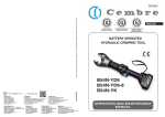
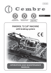
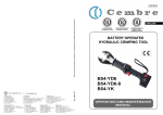
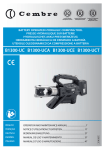
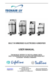
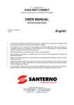
Certified Quality
Management System
Certified Environmental
Management System
Certified Occupational
Health & Safety
Management System
BATTERY OPERATED HYDRAULIC
CRIMPING TOOL
B1500
ENGLISH
B1500A B1500YA
1
14 M 177 E
OPERATION AND MAINTENANCE MANUAL
Die set
FIG. 1
FIG. 2
Battery
11
4
FIG. 3
FIG. 4
"P" dies
12
a)
6
13
13
AU150-C adapter
14
15
15
"15500" series dies
b)
14
semi-circular slotted "U" dies
FIG. 5 (B1500YA)
2
1
12
2
8
3
11
4
10
9
8
5
7
3
6
FIG. 6
3
1
OPERATING BUTTON
2
PRESSURE RELEASE BUTTON
3
LED WORKLIGHT
4
OPENING HEAD PIN
5
OPENING HEAD
6
HANDLE
7
TOUCH BUTTON FOR MENU SELECTION
8
RING FOR SHOULDER STRAP
9
DISPLAY
10
BATTERY
11
BATTERY RELEASE
12
HANDLE
WARNING SYMBOLS
Tool:
Before using the When operating the
tool, carefully read tool, keep hands away
t h e i n s t r u c t i o n s from the danger zone.
in this manual.
Do not operate when
dies are not in place.
Following information applies in member states of the European Union:
USER INFORMATION in accordance with “Directives 2002/95/EC and 2002/96/EC.
The ‘Not in the bin’ symbol above when shown on equipment or packaging means
that the equipment must, at the end of its life, be disposed of separately from other
waste.
The separate waste collection of such equipment is organised and managed by the
manufacturer.
Users wishing to dispose of such equipment must contact the manufacturer and
follow the prescribed guidelines for its separate collection. Appropriate waste separation, collection, environmentally compatible treatment and disposal is intended
to reduce harmful environmental effects and promote the reuse and recycling of
materials contained in the equipment. Unlawful disposal of such equipment will be
subject to the application of administrative sanctions provided by current legislation.
Battery:
Always recycle
the batteries.
Never throw
batteries into fire
or water.
Do not discard batteries
into domestic refuse or
waste disposal.
4
1. GENERAL CHARACTERISTICS
B1500
B1500A
B1500YA
Application range
suitable for installing electrical compression connectors
for Copper conductors up to 800 mm2 (1500 MCM) and
for Aluminum conductors up to 630 mm2 (1250 MCM)
Type of accettable dies:
accepts all “P” type dies commonly
used in industry and the semi-circular slotted dies (U-dies) common
to most 12 ton tools and 14,6 ton
Cembre tools.
Rated crimping force
kN (US sh. ton)
136 (15.3)
Minimum crimping force
kN (US sh. ton)
134,3 (15.1)
Minimum operating pressure
Dimensions (Fig. 7 page 14)
Weight with battery
Motor
bar (psi)
mm (inches)
742 (10762)
525 x 251 x102.5 (20.6 x 9.9 x 4)
kg (lbs)
9,7 (21.3)
V DC
Operating temperature
accepts all
“15500” series
dies commonly
used in industry
18
°C (°F)
-15 to +50 (+5 to +122)
Recommended oil
AGIP ARNICA 32 ou équivalents.
Operating speed
twin speed operation and automatic switching from
a rapid advancing speed of the ram to a slower,
more powerful crimping speed
Safety
maximum pressure valve
Rechargeable battery
type
CB1840L Li-Ion
V / Ah ( Wh)
Weight
Bruit aérien sonore (1)
Vibrations
18 / 4.0 (72)
kg (lbs)
(2)
dB
0,66 (1.45)
LpA 66,9 (A)
LpCPeak 86,9 (C)
2
m/s
LWA 74,9 (A)
0,398
(1)
Directive 2006/42/EC, annexe 1, point 1.7.4.2 letter u)
LpA = weighted continuous acoustic pressure level equivalent.
LpCPeak = maximum value of the weighted acoustic displacement pressure at the work place.
LWA = acoustic power level emitted by the machine.
(2)
(Directive 2006/42/EC, annexe 1, point 2.2.1.1)
Weighted root mean square in frequency of the acceleration the upper limbs are exposed to for each biodynamic
reference axis. Tests carried out in compliance with the indications contained in UNI ENV 25349 and UNI EN 28662
part 1st Standards, and under operating conditions much more severe than those normally found.
Battery charger ASC30-36
type
V / Hz (W)
Input
5
B1500
B1500A B1500YA
EU 27044000
USA/CAN 27046000
220 - 240 / 50 - 60 (85)
115 / 60 (85)
WARNING
Do not use the tool for purposes other than those intended by Cembre.
The operator should concentrate on the work being performed and be
careful to maintain a balanced working position.
Before starting work on electrical equipment, please ensure that either
there are no live parts in the immediate working area or that precautions
are taken for working near live par ts in accordance with EN50110-1.
Do not use this tool on or near energised conductors without proper
personal protective equipment. Failure to observe this warning could
result in severe injury or death.
The tool is unsuitable for continuous use and should be allowed to cool
down following uninterrupted, successive crimping operations; for instance,
having exhausted a fully charged battery in one session, delay battery
replacement for a few minutes.
Protect the tool from rain and moisture. Water will damage the tool and
battery. Electro-hydraulic tools should not be operated in pouring rain.
2. INSTRUCTIONS FOR USE
IMPORTANT: Never pressurise the tool without inserting the dies, this could
cause damage to the head and the ram.
The part reference includes the following:
Hydraulic crimping tool.
Li-Ion rechargeable battery (2 pcs).
Battery charger (model depends on the tool version).
Shoulder strap.
Metal carrying case.
USB cable (Ref. to § 6 page 13).
2.1) Preparation
The tool can be easily carried using either the main handle (12) or the shoulder strap attached to
the two rings (8) (Ref. to Fig. 6).
The main operating positions are : horizontal standing on its feet and vertical standing on its battery. In addition to the main handle (12) the lower handle (6) allows a safer and more balanced
grip when using two hands to hold the tool (Ref. to Fig. 3).
Before starting any work, check the battery charge (Ref. to § 2.8) and recharge
if necessary, following the instructions in the battery charger user manual.
6
To replace the battery, grip the tool as illustrated in Figure 1; press the release button (11) and
push the battery downward unlocking it.
Insert a charged battery from the bottom by sliding it into the guides until it locks.
The display shows the operational parameters of the tool; to customise them proceed
as described in § 2.7.
Select the appropriate die set for the connector to be crimped and insert them into the tool head
as described in § 3.
When introducing or changing dies, the battery must first be removed from the tool.
Insert the conductor into the connector and position the
connector between the die; if necessary open the tool
head by means the locking pin (4) (Ref. to Fig. 2).
Ensure the correct location of the crimp.
NOTE: when more compression is
required, proceed according to the
sequence and direction indicated
in the figure, uniformly spacing the
compressions.
Before carrying out further
crimping operations make
sure the locking pin (4) is completely
inserted: its partial insertion may
damage the tool head.
terminal
uc
d
con
1
tor
2
r
cto
u
nd
co
2
1
1
2
connector
2.2) Die advancement
Press operating button (1) to activate the motor-pump and
advance the lower die.
To halt the advancement, release operating button and the
motor will cut out.
1
Make sure the dies are exactly positioned on the desired crimp
point otherwise re-open dies following instructions as per
§ 2.4 and reposition the connector.
2.3) Compression
By keeping operating button (1) pressed, the motor continues to operate: the ram will gradually
move forward until the two dies touch.
The motor will stop automatically when the set pressure has been reached.
To perform proper compression, press and hold the operating button (1) until the motor
stops automatically.
7
Fm = 134.3 kN
Fm = 134.3 kN
the work cycle, select the appropriate display from the Fp = 102.3 kN
OK
menu (Ref. to § 4). When the operating button is released
before the motor stops automatically, the display will show
Pm = 742 bar
Pm = 742 bar
the peak force (Fp) or the peak pressure (Pp) reached at
OK
P
p
=
565
bar
that instant.
To complete the work, press the operating button again until the motor stops automatically; the display will show the maximum force or pressure reached followed by ‘OK’ to confirm correct operation.
NOTE: To display the momentary force or pressure during
Ï
The display ‘ERROR’, combined with a beep and the LEDs flashing,
indicates an incorrect crimping procedure caused by the work cycle
ERROR
being interrupted before the control parameters (force/pressure) of the tool
are reached. This error appears when the pressure release button has been operated and the
tool has already reached a pressure > 100 bar. In this case, repeat the compression by pressing
and holding the operat ing button until the motor stops automatically.
Ð
2.4) Release of dies
By operating the pressure release button (2), the ram will retract
and open the dies.
To take the dies off their guide, it is sufficient to press the pins and
slip them from the head (Ref. to Fig. 4 and 5).
2
2.5) LED Worklights
Whilst the tool is in operation, the compression area is illuminated by two high luminosity LED Worklights that switch off
automatically at the end of the cycle.
The LED Worklights can be disabled by following the procedure described in § 4.2.
2.6) Head rotation
For ease of operation, the tool head can rotate through 180°, allowing the operator to work in the
most comfortable position.
Do not attempt to rotate the head when the hydraulic circuit is pressurised.
2.7) Capacitive touch button for menu selection
This button is located under the display and allows selection of
various screens (Ref. to § 4); it only works when the display is on.
Wearing gloves or using other objects may inhibit the operation of the
button, therefore use a bare finger to apply only a light touch.
3 SEC.
Do not apply pressure to or stab at the touch button, a light touch using a bare
finger is sufficient. The command pulse is sent when the finger releases the button.
8
2.8) Battery status
The battery is equipped with LED indicators that show the
remaining battery life at any time by pressing the adjacent
button (P):
4 LEDs illuminated: fully charged
2 LEDs illuminated: 50 % capacity
1 LED flashing: minimum charge, replace the battery.
With the battery inserted into the tool, the remaining
battery life can also be checked on the display, via touch
button selection (Ref. to § 4).
P
max.
BATTERY
The screen shown alongside indicates that the battery voltage has
dropped below a minimum safety threshold; under these conditions
the tool will not start, and it is necessary to recharge or replace the battery.
The approximate time to fully recharge a battery is about 80 minutes.
min.
Ï
BATTERY
Ð
BATTERY Ï
Ð
After each working cycle, and after the extraction of the battery from the tool, an integrated
battery cut-off device will operate after 70 s approx.
Then the LED nearest to button (P) will flash 5 times each 14 s approx. The battery will be reactivated
when it is reintroduced into the tool and the operating button is pressed.
2.9) Using the battery charger
Carefully follow the instructions in the battery charger user manual.
3. DIE AND ADAPTER ASSEMBLES
B1500 and B1500A tools directly accept all “P” type dies commonly used in industry and when used
with adapter AU150-C (optional accessory) will accept semi-circular slotted dies (U-dies) common
to most 12 ton tools and 14,6 ton Cembre tools. Depending on the dies to be used, please proceed
as follows:
3.1) Use of “P” dies (Ref. to Fig. 4a)
Press pins (13) and insert half of the “P” die into the upper seat of the head and the other half
into the lower seat of the ram; to disassemble them press the pins (13) and slip them from the
head.
3.2) Use of semi-circular slotted dies (“U” dies) (Ref. to Fig. 4b)
Insert the 2 parts of the AU150-C adapter following the instructions as § 3.1.
Select the appropriate “U” die set for the connector to be crimped.
Press pins (14) and lock the parts of the “U” dies into the upper and lower parts of the AU150-C.
3.3) Use of “15500” series dies (Ref. to Fig. 5)
B1500YA tool directly accepts the “15500” series dies commonly used in industry.
Select the appropriate “15500” die set for the connector to be crimped.
Press pins (15) and lock one die into the upper seat of the head and the other die into the lower
seat of the ram; to disassemble them press the pins (15) and slip them from the head.
9
4. DISPLAY
The OLED display switches on automatically when the operating or pressure release buttons are
pressed, and off after 60 seconds of non-operation.
The display shows:
- The main operational parameters of the tool processed by the circuit board, such as peak pressure or force reached.
- Information on the condition of the tool, such as the charge level, the battery temperature and
maintenance requirements.
- Any operational or procedural ERRORS.
Use the touch button (8) to navigate through the menu screens to manage INFORMATION AND
SELECTION:
4.1) INFORMATION SCREENS: display a pre-determined parameter which will then
appear each time the tool is started and during the entire work cycle.
Fm = 134.3 kN
Fp = 94.5 kN
Fm: Minimum set force, expressed in kN.
Fp: Peak force reached, expressed in kN,
(screen as factory setting)
Fm = 15.1 ton
Fp = 10.61 ton
Fm: Minimum set force, expressed in USA sh. tons.
Fp: Peak force reached, expressed in USA sh. tons.
Pm = 742 bar
Pp = 522.3 bar
Pm: Minimum set pressure, expressed in bar.
Pp: Peak pressure reached, expressed in bar.
Pm = 10762 psi
Pp = 7575 psi
Pm: Minimum set pressure, expressed in psi.
Pp: Peak pressure reached, expressed in in psi.
Battery charge level.
BATTERY
1000
-29000
3
B1500
NR 14AZ541
No. of cycles performed.
No. of cycles before scheduled recommended maintenance.
Cembre logo, tool model.
Tool serial no
10
3 SEC.
To make a selected screen operational and appear at each start-up of the
tool, operate the touch button for at least 3 seconds; a continuous beep
will confirm the setting.
The capacitive menu selection button may not work if touched using objects or when
wearing gloves, therefore always operate it using a bare finger.
4.2) SELECTION SCREENS: control parameters that cannot be set as automatic upon start-up of
the tool, can be changed by operating the touch button:
Enabling/disabling the LED Worklights (factory setting LED ON)
LED
OFF
LED
ON
3 SEC.
LED
OFF
LED
ON
When the screen is displayed, touch the button
for at least 3 seconds to
deactivate for reactivate operation of the LED Worklights
during tool use;
a continuous beep will confirm
the setting.
Return to original factory settings / firmware version
When the ‘RESET’ screen is displayed, return the tool to its factory setting by operating the touch
button for at least 3 seconds; a beep will confirm the setting.
RESET
SW:S1J41AH
The RESET screen also shows the firmware version of the circuit board.
4.3) WARNINGS: these appear during operation and notify the operator of the status
of the tool:
LOW BATTERY: replace the battery.
Ï
Ð
BATTERY Ï NOTE: when the battery Vage falls below a minimum safety threshold, the tool
Ð will not start; although it is still possible to end the work cycle in progress.
BATTERY
Ï30001
Ð
11
BATTERY TEMPERATURE HIGH: remove the battery and wait until it cools
down.
NO. OF CYCLES TO MAINTENANCE REACHED:
the tool continues to work however, it is recommended that it is sent to Cembre
for a complete overhaul (see § 7).
NOTE: this message, together with a beep, will reappear when the tool has been
idle for 30 seconds.
3
4.4) ERRORS: these appear during operation, combined with a beep and flashing
LED Worklights, to notify the operator of procedural or operational errors.
Message
Ï
ERROR
Ð
Ï
001
Ð
Ï
002
Ð
Ï
003
Ð
Ï
004
Error description
Solution
The pressure release button (2)
was pressed before the control
parameters were reached (Force/
Pressure).
Repeat the work cycle and wait for the
motor to stop automatically.
Abnormal power consumption
of the motor for more than 3
seconds.
The tool stops.
Wait for the display to turn off (60 sec.)
or remove and re-insert the battery,
then re-start the tool.
If the error occurs frequently, contact
Cembre.
Output voltage of the pressure
transmitter is out of the pre-set
range.
Repeat the work cycle; if the error
occurs frequently, contact Cembre.
Failure to reach the set pressure
within 30 seconds of continuous
operation of the machine.
Repeat the work cycle; if the error
occurs frequently, contact Cembre.
Overcharging of the battery with
protection tripping.
The tool stops.
Wait for the display to turn off (60 sec.)
or remove and re-insert the battery,
then re-start the tool.
If the error occurs frequently, contact
Cembre.
Ð
Errors are displayed for about 30 seconds before being reset, but will display repeatedly in
the event of permanent anomalies.
5. MAINTENANCE
The tool is robust, completely sealed, and requires very little daily maintenance. Compliance with
the following points, should help to maintain its optimum performance:
5.1) Thorough cleaning
Dust, sand and dirt are a danger for any hydraulic device.
Every day, after use, the tool must be wiped with a clean cloth taking care to remove any residue,
especially close to pivots and moveable parts.
Do not use hydrocarbons to clean the rubber parts.
12
5.2) Storage case
When not in use, the tool should be stored
and transported in the metal case, to
prevent damage.
Metal case: VAL B1500, size 565x410x132
mm (22.2x16.1x5.2 in.), weight 6,7 kg
(14.7 lbs).
6. CONNECTION TO COMPUTER
The memory card integrated in the tool records operating data from
200.000 cycles for transfer via the USB cable supplied.
To view and manage this data, go to www.cembre.com and register in the
dedicated area, then download the free Cembre software CEM_SWBT01.
Keeping the Firmware of the tool updated, via free of charge download
from here, will optimise the tool's performance.
7. RETURN TO Cembre FOR OVERHAUL
In the case of a breakdown, contact your local Agent who will advise you on the problem and give you
the necessary instructions on how to dispatch the tool to our nearest service Centre; if possible, attach
a copy of the Cembre Test Certificate supplied with the tool or, if no other references are available,
indicate the approximate purchase date and the tool serial number.
13
251 (9.9)
FIG. / BILD 7
525 (20.6)
102.5 (4)
mm (inch)
NOTE
____________________________________________________________________________________
____________________________________________________________________________________
____________________________________________________________________________________
____________________________________________________________________________________
____________________________________________________________________________________
____________________________________________________________________________________
____________________________________________________________________________________
___________________________________________________________________________________
14
15
Cembre S.a.r.l.
22 Avenue Ferdinand de Lesseps
91420 Morangis (France)
Tél.: 01 60 49 11 90 - Fax: 01 60 49 29 10
B.P. 37 - 91421 Morangis Cédex
E-mail: [email protected]
www.cembre.fr
Cembre España S.L.
Calle Verano, 6 y 8 - P.I. Las Monjas
28850 Torrejón de Ardoz - Madrid (España)
Teléfono: 91 4852580
Telefax: 91 4852581
E-mail: [email protected]
www.cembre.es
Cembre AS
Fossnes Senter
N-3160 Stokke (Norway)
Phone: (47) 33361765
Telefax: (47) 33361766
E-mail: [email protected]
www.cembre.no
Cembre GmbH
Heidemannstraße 166
80939 München (Deutschland)
Telefon: 089/3580676
Telefax: 089/35806777
E-mail: [email protected]
www.cembre.de
Cembre Inc.
Raritan Center Business Park
181 Fieldcrest Avenue
Edison, New Jersey 08837 (USA)
Tel.: (732) 225-7415 - Fax: (732) 225-7414
E-mail: [email protected]
www.cembreinc.com
This manual is the property of Cembre: any reproduction is forbidden without written permission.
Cembre Ltd.
Dunton Park
Kingsbury Road, Curdworth - Sutton Coldfield
West Midlands B76 9EB (Great Britain)
Tel.: 01675 470440 - Fax: 01675 470220
E-mail: [email protected]
www.cembre.co.uk
cod. 6261390
www.cembre.com
Cembre S.p.A.
Via Serenissima, 9
25135 Brescia (Italia)
Telefono: 030 36921
Telefax: 030 3365766
E-mail: [email protected]
www.cembre.it
16