1
Agilent B1500A
Semiconductor Device
Analyzer
Self-paced Training Manual
Agilent Technologies
Notices
© Agilent Technologies 2005 - 2008
Manual Part Number
No part of this manual may be reproduced
in any form or by any means (including
electronic storage and retrieval or translation into a foreign language) without prior
agreement and written consent from Agilent Technologies, Inc. as governed by
United States and international copyright
laws.
B1500-90044
Edition
Edition 1, September 2005
Edition 2, May 2006
Edition 3, January 2007
Edition 4, June 2007
Edition 5, February 2008
Edition 6, October 2008
Agilent Technologies
5301 Stevens Creek Blvd
Santa Clara, CA 95051 USA
Warranty
The material contained in this document is provided “as is,” and is subject to being changed, without notice,
in future editions. Further, to the maximum extent permitted by applicable
law, Agilent disclaims all warranties,
either express or implied, with regard
to this manual and any information
contained herein, including but not
limited to the implied warranties of
merchantability and fitness for a particular purpose. Agilent shall not be
liable for errors or for incidental or
consequential damages in connection
with the furnishing, use, or performance of this document or of any
information contained herein. Should
Agilent and the user have a separate
written agreement with warranty
terms covering the material in this
document that conflict with these
terms, the warranty terms in the separate agreement shall control.
Technology Licenses
The hardware and/or software described in
this document are furnished under a
license and may be used or copied only in
accordance with the terms of such license.
Restricted Rights Legend
If software is for use in the performance of
a U.S. Government prime contract or subcontract, Software is delivered and
licensed as “Commercial computer soft-
ware” as defined in DFAR 252.227-7014
(June 1995), or as a “commercial item” as
defined in FAR 2.101(a) or as “Restricted
computer software” as defined in FAR
52.227-19 (June 1987) or any equivalent
agency regulation or contract clause. Use,
duplication or disclosure of Software is
subject to Agilent Technologies’ standard
commercial license terms, and non-DOD
Departments and Agencies of the U.S. Government will receive no greater than
Restricted Rights as defined in FAR
52.227-19(c)(1-2) (June 1987). U.S. Government users will receive no greater than
Limited Rights as defined in FAR 52.227-14
(June 1987) or DFAR 252.227-7015 (b)(2)
(November 1995), as applicable in any
technical data.
In This Manual
This document is the self-paced training manual to help you to understand what is Agilent
B1500A, what functions the B1500A has, how to use the B1500A, and what applications
the B1500A contributes to.
CAUTION
The test setup data described in this manual are only examples. If these example data
damage your devices, Agilent is NOT LIABLE for the damage.
•
Module 1. Introduction
This module explains the product concept and the key features of the B1500A/
EasyEXPERT. You will learn about what is the B1500A.
•
Module 2. Getting Started
This module explains the basic operations of the B1500A. You will learn about how to
launch B1500A/EasyEXPERT and how to perform application test and quick test.
•
Module 3. Data Display and Management
This module explains the data display and analysis capabilities of the EasyEXPERT
software. You will learn how to use analysis tools, how to change display setup, and
how to print/export test result data.
•
Module 4. Classic Test Environment
This module explains the classic test mode of the EasyEXPERT. You will learn how to
create the classic test setup in the course exercises.
•
Module 5. Basic Measurement
This module explains the basic I-V sweep measurement function and the cabling and
fixturing issues. You will learn how to measure I-V curves in the course exercises.
•
Module 6. Low Current Measurement
This module explains the low current measurement technique. You will learn how to
measure the low current in the course exercises.
•
Module 7. Measurement Functions
This module explains the measurement functions available with the B1500A. You will
learn how to use various measurement functions in the course exercises.
•
Module 8. Capacitance Measurement
This module explains the capacitance measurement function. You will learn how to
measure the capacitance in a course exercise.
•
Module 9. Modifying Application Test Definitions
This module explains a modification example of an application test definition. You will
learn how to modify the definition in a course exercise.
•
Module 10. Creating Your Test Definitions
This module explains about the application test definition. You will learn how to create
your application test definition in a course exercise.
•
Module 11. Advanced Definitions and Operations
This module explains how to control external GPIB devices, how to call an execution
file, how to perform a repeat measurement, and how to use the prober control script.
•
Module 12. Miscellaneous Operations
This module explains what is the status indicator, what is the automatic data export
function and the automatic data record function, how to perform selftest and
calibration, how to perform SMU zero offset cancel, and such.
•
Module 13. SPGU Control and Applications
This module explains the SPGU Control classic test. You will learn how to create the
classic test setup and the applications using SPGU in the course exercises.
EasyEXPERT is a trademark of Agilent Technologies. All other trademarks are the
property of their respective owners.
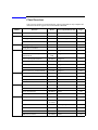
Class Exercises
Class exercises use the test setup listed below. The test setup data are only examples and
included in the Demo.xpg file stored in the Manual CD-ROM.
Module
Exercise
Device
Test setup/definition/data
Page
Module 1
no exercise
Module 2
Id-Vd measurement
MOSFET
CMOS: Id-Vd
2-19, 27
Id-Vg, gm-Vg measurement
MOSFET
CMOS: Vth gmMax
2-19, 27
B2200/E5250 switch control
-
Id-Vg, gm-Vg measurement
MOSFET
Module 3
Using Preview window
Module 4
3-28
-
3-31
Trng Id-Vd
4-25
Multi Channel I/V Sweep
Measurement
Bipolar Tr
LED
Trng Multi
4-37
I/V List Sweep Measurement
MOSFET
Trng List
4-51
I/V-t sampling measurement
0.1 μF
Trng Sampling
4-64
Trng CV
4-76
Trng Switch
4-81
Trng C-f
4-88
Direct Control (C-f measurement)
MOSFET
0.1 μF
Id-Vd measurement
MOSFET
IDVD, Id-Vd
5-7
SMU series connection
511 kohm
IRVR
5-24
Parallel
5-28
REKELV
5-38
SMU parallel connection
Re measurement, kelvin connection
Module 7
GMMAX.xtr
MOSFET
B2200/E5250 switch control
Module 6
2-32
Id-Vd measurement
C-V sweep measurement
Module 5
-
-
1 ohm
Bipolar Tr
Leak current measurement
-
Zero-check
6-9
Ultra low current measurement
-
Zero-check-ASU
6-19
Id-Vg measurement
MOSFET
IDVG
6-20
Gummel plot
Bipolar Tr
GUMMEL
6-25
SMU pulse mode
MOSFET
IDVD-Pulse
7-8
RC measurement
0.1 μF and
511 kohm
RC-sampling-log
7-16
Negative hold time
511 kohm
R-sampl-neg-hold
7-22
Auto analysis
MOSFET
GMMAX
7-28
Bias hold function
LED
LED
7-35
SMU series resistor
511 kohm
IV-res
7-43
Module
Exercise
Device
Test setup/definition/data
Page
Module 8
C-V sweep measurement
MOSFET
CV-1MHz
8-6
Module 9
Modifying application test
definition
MOSFET
Trng IdVd Vth.xtd
9-14
Trng idvd idvg2.xtd
9-29
Trng idvd idvg3.xtd
9-32
Using auto analysys twice
MOSFET
Vth gmMax and Id
9-34
Using vector data
MOSFET
Trng Cgg-Vg
9-42
Module 10
Creating application test definition
MOSFET
Trng idvd idvg.xtd
10-17
Module 11
no exercise
Module 12
no exercise
Module 13
Charge pumping
MOSFET
Charge Pumping 4T 0.1V
step
13-20
Flash memory
MOSFET
Demo-S-NorFlash
Endurance
13-29
ALWG output
511 kohm
ALWG monitor
13-36
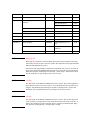
NOTE
Demo.xpg file
Demo.xpg file is required to create the Demo preset group which contains the test setup
data used by the class exercises. And it is stored in the \data folder on the Agilent B1500A
Manual CD-ROM, Edition 4 or later.
The Demo preset group should be created before starting the class exercise. To create the
preset group, launch EasyEXPERT and import the file by using the Preset Group Import
dialog box opened by clicking My Favorite Setup > Preset Group > Import Preset Group.
The test setup data are only examples for the class exercises.
NOTE
.xtd files
The \data folder on the Manual CD-ROM stores some .xtd files. They are the application
test definitions used by some class exercises. To use the definition file, import the file by
using the Test Definition Import dialog box opened by clicking Library > Import Test
Definition. The test definition data are only examples for the class exercises.
NOTE
.xtr files
The \data folder on the Manual CD-ROM stores some .xtr files. They are the sample test
results created by executing the test setup which has the same name as the result data. To
display these sample test results, import the files by using the Test Result Import dialog
box opened by clicking Results > Transport Data > Import.
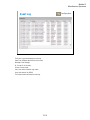
Test Setup for Class Exercises
The Demo preset group contains the following test setup. The setup data are only examples
for the class exercises. The following table lists the test setup name in alphabetical order.
Test Setup Name
Description
ALWG monitor
511 kohm sampling measurement with SPGU ALWG output
Charge Pumping 4T
0.1V step
MOSFET Icp-Vbase measurement
CV-1MHz
MOSFET Cgs-Vg measurement
Demo-S-NorFlash
Endurance
MOSFET Endurance test
Fowler-Nordheim
Fowler-Nordheim (FN) plot
GMMAX
MOSFET sqrt_Id-Vg, PEAK-Vg measurement
GUMMEL
Bipolar transistor gummel plot
IDVD
MOSFET Id-Vd measurement
IDVD-Pulse
MOSFET pulsed Id-Vd measurement
Id-Vd
MOSFET Id-Vd measurement, Application Test
IDVG
MOSFET Id-Vg measurement
IRVR
511 kohm I-V measurement
IV-res
511 kohm I-V measurement with SMU series resistor
LED
LED I-V measurement
Parallel
1 ohm I-V measurement, voltage force and current measurement
PG monitor
511 kohm sampling measurement with SPGU VPULSE output
RC-sampling-log
RC sampling measurement, log sampling
REKELV
Bipolar transistor Re measurement
R-sampl-neg-hold
511 kohm sampling measurement with negative hold time
Subthreshold
MOSFET subthreshold measurement
Trng C-f
Direct Control (C-f measurement)
Trng Cgg-Vg
Cgg-Vg modification example for multi-frequency
Trng CV
MOSFET C-V measurement
Trng Id-Vd
MOSFET Id-Vd measurement
Test Setup Name
Description
Trng List
MOSFET Vth-gmmax measurement using I/V List Sweep
Trng Multi
Multi Channel I/V Sweep (Bipolar transistor and LED)
Trng Sampling
0.1 μF sampling measurement
Trng Switch
B2200/E5250 switch setup, Input 1-3-5-7 to Output 1-3-5-7
Vth gmMax and Id
Vth gmMax modification example to use auto analysis twice
Zero-check
SMU open measurement
Zero-check-ASU
SMU open measurement with ASU
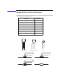
Required Devices for Class Exercises
To perform the class exercises, you need the device set (Agilent part number 04156-87001)
which contains the following devices.
Description
Quantity
N-channel MOSFET
2 ea.
NPN Bipolar Transistor
1 ea.
Red Miniature LED
1 ea.
0.1 μF Capacitor 50 V
1 ea.
1.0 Ω Resistor 1/8 W
1 ea.
1.1 kΩ Resistor 1/8 W
1 ea.
511 kΩ Resistor 1/8 W
1 ea.
N-ch MOSFET
NPN bipolar Transistor
LED
Brown
Black
Black
Silver
1 ohm Resistor
Brown
Brown
Black
Brown
1.1 kohm Resistor
Green
Brown
Brown
Orange
511 kohm Resistor
0.1 uF Capacitor
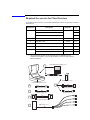
Required Accessories for Class Exercises
To perform the class exercises, you need the following accessories. Prepare the accessories
shown below.
Designation
1
Description
Test Fixture
Model No.
Qty.
16442A/B a
1 ea.
28 pin socket module
1 ea.
Connection wire
6 ea.
2
Triaxial Cable
16494A
4 ea.
3
Interlock Cable
16493J
1 ea.
4
Kelvin Triaxial Cable, for Module 5
16493K
1 ea.
5
CMU Cable, for Module 8
N1300A
1 ea.
6
Atto Sense/Switch Unit, for Module 6
E5288A
1 ea.
ASU control cable, triax cable, for Module 6
16493M
1 ea.
a. The 16058A Test Fixture for the 4145A/B may be substituted for the
16442A/B Test Fixture. If you use the 16058A, you also need the 16435A
Interlock Adapter.
28 pin DIP Socket Module (1ea.)
1
Connection Wire (6ea.)
E5288A ASU (1ea.)
16442A/B Test Fixture (1ea.)
6
2
Triaxial Cable (4ea.)
Control Cable (1ea.)
3
INTLK Cable (1ea.)
4
Kelvin Triaxial Cable (1ea.)
5
CMU Cable (1ea.)
Triaxial Cable (1ea.)
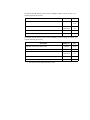
To perform the flash memory class exercise in Module 13 and if you use the ASU, you
need the following accessories.
Description
Model No.
Qty.
E5288A
Total
3sets
16494A or
equivalent
Total
7ea.
BNC-SMA Cable
16493P
3 ea.
SMA-SMA Cable, for synchronization of SPGU
16493Q
2 ea.
ASU (Atto Sense/Switch Unit) with control cable
Triaxial Cable
To perform the flash memory class exercise in Module 13 and if you use the selector, you
need the following accessories.
Description
Model No.
Qty.
SMU/PG selector with control cable a
16440A
2 sets
Selector adapter with control cable
16445A
1 set
16494A or
equivalent
Total
7ea.
BNC-SMA Cable
16493P
3 ea.
SMA-SMA Cable, for synchronization of SPGU
16493Q
2 ea.
Triaxial Cable
a. One selector can be replaced with one ASU.
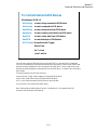
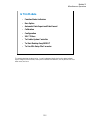
Contents
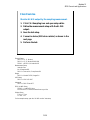
Module 1. Introduction
•
New Features
•
EasyEXPERT
•
To Perform Easy Application Test
•
User Interface
•
Modular Mainframe
•
SCUU/GSWU
•
ASU
•
SMU/Pulse Generator Selector
•
B2200/E5250 Switch Control
•
Desktop EasyEXPERT
Module 2. Getting Started
•
To Turn on/off B1500A
•
To Launch EasyEXPERT
•
To Specify/Create Workspace
•
To Perform Application Test
•
To Save/Recall Your Test Setup
•
To Export/Import Your Preset Group
•
To Export/Import Test Record
•
To Perform Quick Test
•
To Control Switching Matrix
•
To Manage Data Display Window
Contents-1
Contents
Module 3. Data Display and Management
•
Data Display window
•
Graph Analysis Tools
•
Data Status
•
To Change Graph/List/Display Setup
•
To See Print Preview
•
To Print Display Data
•
To Copy Graph Plot/List Data
•
To Save Analysis Result
•
To Use Preview Window
Module 4. Classic Test Environment
•
Classic Test Execution Mode
•
I/V Sweep Measurement
•
Multi Channel I/V Sweep Measurement
•
I/V List Sweep Measurement
•
I/V-t Sampling Measurement
•
C-V Sweep Measurement
•
Switching Matrix Control
•
Direct Control
Contents-2
Contents
Module 5. Basic Measurement
•
SMU Fundamentals
•
Classic Test Environment
•
SMUs Connected in Series or Parallel
•
Cabling and Fixture Issues
•
Kelvin and Driven Guard
•
Probes and Prober Connections
•
Triax and Coax Adapters
•
Safety Interlock Issues
Module 6. Low Current Measurement
•
Low-Current Measurement Challenges
•
Calibration and Zero Cancel
•
Effect of Cable Movement
•
ASU for Ultra Low-Current Measurement
•
Low-Current Subthreshold
•
Trade-Off Speed Vs Accuracy
•
Low-Current Gummel Plot
•
Low-Current Gate Oxide Leakage
Contents-3
Contents
Module 7. Measurement Functions
•
SMU Pulsed Sweep Measurement
•
I/V-t Sampling Measurement
•
Negative Hold Time for High Speed Sampling
•
Auto Analysis
•
SMU Filter
•
SMU Series Resistor
•
Standby Function
•
Bias Hold Function
Module 8. Capacitance Measurement
•
CMU Fundamentals
•
Classic Test Environment
•
CMU Calibration
•
SCUU for IV/CV Switching
•
GSWU for Accurate Capacitance Measurement
•
ASU for IV/CV Switching
Contents-4
Contents
Module 9. Modifying Application Test Definitions
•
To Open Application Test Definition
•
To Modify Test Definition
•
To Use Debug Tools
•
To Use Built-in Functions
•
To Add Data Display
•
To Use Auto Analysis
•
To Use Test Setup Internal Variables
•
To Use Auto Analysis twice (as Class Exercise)
•
To Use Vector Data (as Class Exercise)
Module 10. Creating Your Test Definitions
•
What is Test Definition
•
What is Test Contents
•
To Open Test Definition Editor
•
To Define Test Specification
•
To Define Test Contents
•
Available Elements
•
Available Variables
•
To Define Test Output
Contents-5
Contents
Module 11. Advanced Definitions and Operations
•
To Control External GPIB Devices
•
To Call Execution Files
•
To Perform Repeat Measurements
•
Prober Control Script
Module 12. Miscellaneous Operations
•
Function Status Indicator
•
Run Option
•
Automatic Data Export and Data Record
•
Calibration
•
Configuration
•
XSLT Samples
•
To Enable System Controller
•
To Start Desktop EasyEXPERT
•
To Use 415x Setup File Converter
Contents-6
Contents
Module 13. SPGU Control and Applications
•
High Voltage SPGU
•
SPGU Control
•
Pulse Generator Mode
•
Charge Pumping
•
Flash Memory Test
•
ALWG Mode
Contents-7
Contents
Contents-8
10
Creating Your Test Definitions
Module 10
Creating Your Test Definitions
In This Module
•
What is Test Definition
•
What is Test Contents
•
To Open Test Definition Editor
•
To Define Test Specification
•
To Define Test Contents
•
Available Elements
•
Available Variables
•
To Define Test Output
This section explains how to create your test definition. You will perform the above tasks to create
the definition.
10-2
Module 10
Creating Your Test Definitions
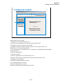
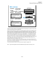
What is Test Definition
Test Specification
Test Output
•Multi display mode
•Variables
•Analysis parameters
•Test result display
•X-Y graph
•Data list
•Parameter display
•Test name
•Test description
•Variables
•Device parameters
•Test parameters
•Entry fields
Test Contents
•Local variables
•Test execution flow
•Test setup
•Classic test
•Application test
•My Favorite setup
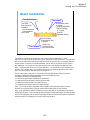
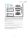
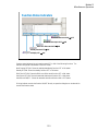
Test definition consists of test specification, test contents, and test output setup. The test
specification contains test name, description, device parameters, and test parameters. The parameters
will be the variables used to pass the test conditions to the test execution flow or test setup defined in
the test contents. Especially for the test parameters, you can specify the position of entry field for
each parameter. You can see the entry fields when the main screen displays this application test
setup. The test contents are the core of the test definition. You will define the local variables, test
execution flow, and test setup. You can define the test setup by selecting application tests, classic
tests, or my favorite setup, and entering the test conditions.
The test output setup is optional. If you have the following requirements, declare the analysis
parameters and define the display parameters on the Test Output tab screen.
-To send the test data to the subsequent tests
-To make the program branching depends on the test data
-To display/record the calculation result using the test data
-To display/record the test data of this application test
-To change the multi display mode of this application test
Note: You can use the device parameters, test parameters, and analysis parameters in the test
execution flow (program flow) of the test contents without declaration of local variables.
Note: If the multi display mode is Disabled, the all test result data will be displayed on the singular
Data Display window. If the multi display mode is Enabled, the test result data of the same test setup
name will be displayed on the exclusive Data Display window and the test result data of the different
test setup name will be displayed on the new Data Display window.
10-3
Module 10
Creating Your Test Definitions
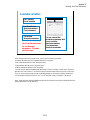
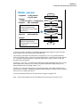
What is Test Contents
Test Output
Test Specification
Variables
•Device parameters
•Test parameters
Variables
•Analysis parameters
Analysis
Local variables
Miscellaneous
Program Component
Classic Test
My Favorite
Application Test
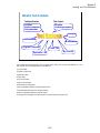
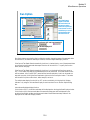
Test contents are the test execution flow (program flow), and is the core of the test definition. In the
test contents, the following elements can be defined.
•Local variables
•Program components
•Application tests
•Classic tests
•My Favorite setup
•Analysis components
•Miscellaneous components
•Device parameters defined in the test specification
•Test parameters defined in the test specification
•Analysis parameters defined in the test output
The program is executed from top to bottom in the test execution program list.
10-4
Module 10
Creating Your Test Definitions
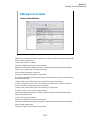
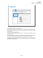
To Open Test Definition Editor
Define New Test…
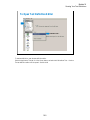
To start test definition, open the test definition editor.
Select the Application Test tab, click the Library button, and select the Define New Test… function.
The test definition editor will be opened. See next slide.
10-5
Module 10
Creating Your Test Definitions
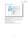
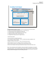
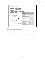
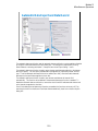
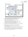
To Define Test Specification
Set test information
Define device parameters
Set properties
of parameter
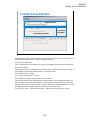
The test definition editor provides three tabs, Test Specification, Test Contents, and Test Output. At
first define the test specification. Click the Test Specification tab.
In the Test Information area:
•Click the right button in the Category field to specify the category the new test definition belongs.
•Enter the Test Name.
•Select the Icon that will be displayed on the list area below the Library button of the main screen. It
is the image file used to select the test definition. See previous slide.
•Enter the Description of the test.
In the Device Parameters Definition area:
•Click Add button to display the entry fields for the parameter.
•Set the Name, Default value, and Description for the parameter. When you add a parameter, you
will see the entry fields at the Properties area. The area shows you the properties (minimum value,
maximum value, number of effective digits, resolution, and unit) for the device parameter or the test
parameter specified by the radio button put on the left of the parameter name.
For the Typical Values… button and the Symbols… button, see online help or User’s Guide.
10-6
Module 10
Creating Your Test Definitions
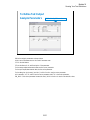
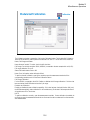
To Define Test Specification
Set properties
of parameter
Define test parameters
In the Test Parameters Definition area:
•Select the Background that will be displayed on the application test setup area of the main screen.
Usually it is the image that shows the device connections.
•Set the Name, data type, Default value, and Description for the parameter. When you add a
parameter, you will see the entry fields at the Properties area. The area shows you the properties
(minimum value, maximum value, number of effective digits, resolution, and unit) for the device
parameter or the test parameter specified by the radio button put on the left of the parameter name.
•Set the X, Y, and Width values to specify the position of entry field displayed on the application test
setup area.
•Check the Align box to set the X origin of entry field to the left edge of the entry field. Uncheck
this box to set it to the left edge of the parameter name placed left next to the entry field.
•Check the Ext box. The entry field will be put on the Extended Test Parameters dialog box that is
displayed by clicking the Extended Setup button on the application test setup area of the main screen.
10-7
Module 10
Creating Your Test Definitions
Setup example
This example sets:
Category: Exercise (This category may be created by the class exercise in Module 9)
Test Name: Trng idvd idvg
Icon: MOSFET.bmp
Device parameters:
Hold and Delay
Background: Vth_Const_Id.PNG
Test parameters:
Drain, Gate, Source, Subs, Idcomp, Igcomp
IdVd_V1start, IdVd_V1step, IdVd_V1stop, IdVd_V2start, IdVd_V2step, IdVd_V2nop
IdVg_V1start, IdVg_V1stop, IdVg_V1step, IdVg_Vdrain
Vsource, Vsubs
Entry field properties: 80 (width) x 30 (distance in vertical direction)
Press the Layout… button to open the Define Layout dialog box.
10-8
Module 10
Creating Your Test Definitions
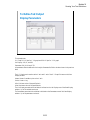
Setup example - Layout
Primary Entry Field
The Define Layout dialog box is used to define the layout of the test parameter entry fields displayed
on the application test setup screen.
The following methods are available for selecting the entry fields.
•Click on the entry field. Multiple entry fields can be selected by clicking on the entry field while
holding down the Ctrl key on the keyboard.
•Drag the mouse to draw a rectangle around multiple entry fields.
•Select Select All from the EDIT menu to select all entry fields.
The selected entry fields are outlined by the blue rectangles. The primary entry field, which is the
base for layout operations, is surrounded by a highlighted blue rectangle. Only one primary entry
field can be selected. To change the primary entry field, click on a selected entry field. The entry
field is always that was most recently clicked will be the primary entry field.
The following methods are available for releasing (unselecting) the selected entry fields.
•Click the selected entry field while holding down the Shift key on the keyboard.
•Click outside of the selected entry fields to release all selected entry fields.
The following methods are available for defining the layout of the selected entry fields.
•Drag & drop with the mouse to move the selected entry field(s).
•Change the X/Y values in the property window to move the selected entry field(s).
•Press the arrow keys on the keyboard to move the selected entry field(s).
•Use the functions in the Align menu to align the selected entry field(s) to the primary entry field.
•Use the functions in the Distribute menu to evenly distribute the selected entry fields horizontally or
vertically.
•Use the functions in the Centralize menu to move the horizontal or vertical center of all selected
entry fields to the horizontal or vertical center of the entry field area.
For more information, see online help or User’s Guide.
10-9
Module 10
Creating Your Test Definitions
Result example
This is a result example of the test specification setup shown in the previous pages.
10-10
Module 10
Creating Your Test Definitions
To Define Test Contents
4. Select available element
1
5. Click Insert or
desired button
2. Define the local variables used
in this test contents
3. Specify the line
to insert element
or to be edited
6. Define the setup required for
the highlighted line (element)
Starting to define the test contents:
1. Highlight the Local Variables Definition line.
2. Define the local variables used in this test contents (test execution flow).
3. Highlight the line that an element has to be inserted.
4. Highlight an element of Program Component, Application Test, Analysis, Classic Test,
Miscellaneous, or My Favorite Setup tab menu.
5. Click the Insert button of the Edit tab menu. The element will be inserted between the highlighted
line and the next line.
6. Define the required setup.
To edit the test contents:
1. Optional. Highlight the Local Variables Definition line.
2. Optional. Define the local variables used in this test contents (test execution flow).
3. Highlight the line to be edited.
4. Highlight an additional element if you need.
5. Click the desired button if you need.
6. Define the required setup if you need.
Repeat this to create the test contents (test execution flow).
10-11
Module 10
Creating Your Test Definitions
Available elements
Program Component
Application Test
Analysis
Classic Test
Miscellaneous
My Favorite
Available elements are shown above. The Program Component provides the typical program
statements such as IF, LOOP, FOR, and so on. They are used to control the test execution flow. The
Application Test, Classic Test, and My Favorite are used to define the test setup/test condition. The
Analysis provides the elements used to control auto analysis function and data display. And the
Miscellaneous provides other useful elements. For details of elements, see online help or user’s
guide.
10-12
Module 10
Creating Your Test Definitions
Available variables
Assign to external variables…
Test Contents
•Local variables
Test Specification
•Device parameters
•Test parameters
Test Output
•Analysis parameters
You can connect the
variables in test setup with
•Local variables
•Device parameters
•Test parameters
•Analysis parameters
Do not set the same name
for variables and
parameters. The name
must be unique.
In the test execution flow (program flow), you can use the following variables.
•Variables defined by the Local Variables Definition component
•Device parameters defined in the Test Specification
•Test parameters defined in the Test Specification
•Analysis parameters defined in the Test Output
You may want to read the parameters/variables used in Classic Test setup or Application Test setup
defined in the Test Contents. Then use the External Variables Setup dialog box or built-in functions.
They can connect the test setup internal variables/parameters to the external variables listed above.
For the example variable connections, see “To Use Test Setup Internal Variables” in Module 9.
Note: Application test internal parameter/variable to be connected to an external variable must be the
analysis parameter in its test definition.
10-13
Module 10
Creating Your Test Definitions
Defining local variables
Local Variables Definition
Add Numeric Variable button displays the Numeric Variable area that provides the following fields.
•Name: Numeric variable name
•Value: Initial value of the variable
•Description: Additional information for the variable
Add Vector Variable button displays the Vector Variable area that provides the following fields.
•Name: Vector variable name. Two dimensional array.
•Count: Number of elements, or array size
•Description: Additional information for the variable
This area also provides the following radio button used to specify how to set the initial value of the
array data automatically.
• Assign Linear Values FROM [value of first element] TO [value of last element]
If Count>1, this sets first value + (N-1) x (last value-first value)/(Count-1) to the N-th element. If
Count=1, this sets first value(=last value) to the element.
• Assign Linear Values FROM [value of first element] STEP [step value]
This sets first value + (N-1) x step to the N-th element.
Add String Variable button displays the String Variable area that provides the following fields.
•Name: String variable name
•Value: Initial value of the variable
•Description: Additional information for the variable
Add Module Variable button displays the Module Variable area that provides the following fields.
•Name: Module variable name
•Description: Additional information for the variable
10-14
Module 10
Creating Your Test Definitions
Editing test contents
•Block Selection
•Insert
•Delete
•Copy
•Cut
•Paste
The Edit tab provides the following buttons:
•Block Selection/Line Selection toggle button selects the edit target selection mode. In the line
selection mode, clicking line just selects the line. In the block selection mode, clicking line selects
the block the line belongs.
•Insert button inserts the specified element between the highlighted line and the next line.
•Delete button deletes the highlighted line.
•Copy button copies the highlighted line to the clipboard.
•Cut button moves the highlighted line to the clipboard.
•Paste button inserts the line in the clipboard between the highlighted line and the next line.
10-15
Module 10
Creating Your Test Definitions
Debug menu
•Run
•Abort
•Stop
•Break
•Inspect
The Debug tab menu provides the following buttons:
•Run button starts the debug (executes the test flow). During execution, the label changes to Pause.
Clicking Pause button pauses the execution, and changes the label to Run that is used to continue the
debug (execution).
•Abort button aborts the debug (execution).
•Step button executes the highlighted line of the test flow. Clicking the button repeatedly continues
the execution by a line.
•Break button sets/releases the break point. For the break point, this button releases the break point
from the highlighted line. Program execution will break at the break point automatically.
•Inspect button is available when the debug (execution) is paused or broken. This button opens the
Variable Inspector used to monitor value of device parameters, test parameters, analysis parameters,
local variables, or system variables.
10-16
Module 10
Creating Your Test Definitions
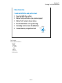
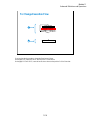
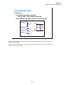
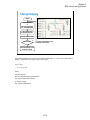
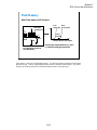
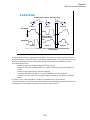
Class Exercise
Create test definition and perform test.
1. Open test definition editor.
2. Define Test Specification (see previous page)
3. Define Test Contents shown below.
4. Save the definition as Trng idvd idvg.
5. Use debug tools to check the definition.
6. Connect device, and perform test.
SMU4
SMU3
SMU1
SMU2
Test Contents:
Local Variables Definition
BLOCK
IDVD
Message
IF Yes=0
END
END IF
GMMAX
END BLOCK
10-17
Module 10
Creating Your Test Definitions
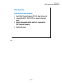
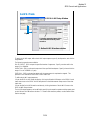
Test Definition Example
variables
Use IDVD and GMMAX in the Demo preset group (My Favorite Setup) for the test setup.
Use the variables defined in the Test Specification to set the Unit on the Channel Setup, the source
values on the Measurement Setup, the Min and Max values on the Display Setup, and so on.
For the example definition, open the Trng idvd idvg definition stored in the \data folder on the
Manual CD-ROM. The Manual CD-ROM stores the example test setup and definition data used in
this manual.
10-18
Module 10
Creating Your Test Definitions
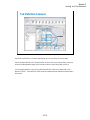
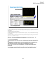
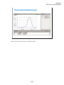
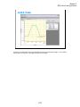
Measurement Result Example
This is a test result example displayed on the Data Display window.
10-19
Module 10
Creating Your Test Definitions
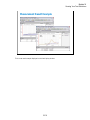
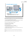
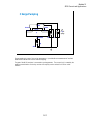
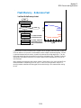
To Define Test Output
2. Define the analysis parameters
1
6. Select the multi display mode
Comply with above level
Enable
Disable
3. Specify X axis and Y axis
4. Select variables to list
5. Select parameters
to display
The test output setup is optional. If you have the following requirements, define the analysis
parameters and set the display parameters.
-To send the test result data to the subsequent tests in an application test
-To make the program branching depends on the test result
-To make the calculation using the test data in the Test Contents
-To display/record the test result of this application test
-To change the multi display mode of this application test
To define the test output:
1. Check the Define own Output Parameters box.
2. Click the Define Analysis Parameters… button. And define the analysis parameters on the
Analysis Parameter Definition window.
3. Specify X axis and Y axis of the X-Y Graph of the Data Display window.
4. Select variables to list in the List Display area of the Data Display window.
5. Select variables to display in the Parameters area of the Data Display window.
6. Select the multi display mode using the Allocate Data Display for each test pull-down menu.
Note: If the multi display mode is Disabled, the all test result data will be displayed on the singular
Data Display window. If the multi display mode is Enabled, the test result data of the same test setup
name will be displayed on the exclusive Data Display window and the test result data of the different
test setup name will be displayed on the new Data Display window.
10-20
Module 10
Creating Your Test Definitions
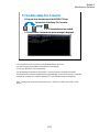
To Define Test Output
Analysis Parameters
Define Analysis Parameters…
Define the analysis parameters as shown below:
At the Vector Parameters area or the Scalar Parameters area:
1. Click the Add button.
2. Enter the Name, Unit, and Description of the parameter.
For the sweep output/measurement data, use the vector parameter.
For the spot output/measurement data, use the scalar parameter.
For the data given by the max( ) and min( ) built-in function, use the vector parameter.
In this example, VG, ID, and GM are the vector parameter and VTH is the scalar parameter.
GM_MAX is the vector parameter because the max( ) built-in function is used to calculate this value.
10-21
Module 10
Creating Your Test Definitions
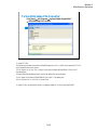
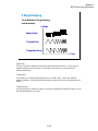
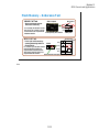
To Define Test Output
Display Parameters
This example sets:
X-Y Graph: ID-VG plot for Y1-X graph and GM-VG plot for Y2-X graph
List Display: VG, ID, and GM
Parameters: GM_MAX and VTH
All parameters must be defined in the Analysis Parameter Definition window shown in the previous
slide.
The X-Y Graph area is used to set the X axis and Y axis of the X-Y Graph Plot area on the Data
Display window.
•Name: Name of variable to plot on the X axis
•Scale: Linear or Log
•Min: Minimum value of the specified axis
•Max: Maximum value of the specified axis
The List Display area selects the variables to be listed on the List Display area of the Data Display
window. Up to 20 variables can be set.
The Parameters area selects the variables to be listed on the Parameters area of the Data Display
window. Up to 20 parameters can be set.
10-22
11
Advanced Definitions and Operations
Module 11
Advanced Definitions and Operations
In This Module
•
To Control External GPIB Devices
•
To Call Execution Files
•
To Perform Repeat Measurements
•
Prober Control Script
11-2
Module 11
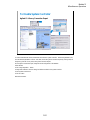
Advanced Definitions and Operations
To Control External GPIB Devices
Miscellaneous: GPIB I/O
Write String
to send a string command to GPIB device
Write Value
to send a command to GPIB device
Read String
to read a string value from GPIB device
Read Value
to read a numeric value data from GPIB device
Read List
to read a vector data from GPIB device
Read STB
to read status byte of GPIB device
GP-IB Control Group Execution Trigger
Device Clear
Go To Local
Local LockOut
You can control external GPIB devices from the EasyEXPERT by using the GPIB I/O statement.
The GPIB I/O statement provides the write/read functions shown above. Select a write function and
enter the necessary parameters to send a command to the GPIB device. Select a read function and
enter the necessary parameters to read response from the GPIB device. For details, see online help or
User’s Guide.
The followings are the GPIB Control functions.
•Group Execution Trigger: Sends a trigger to the specified GPIB device.
•Device Clear: Sends a device clear to the specified GPIB device.
•Go To Local: Returns the specified GPIB device to the local state.
•Local LockOut: Locks the specified GPIB device.
Note: Before starting, enable System Controller. See Module 12. Also establish the GPIB
connection with the external GPIB devices.
11-3
Module 11
Advanced Definitions and Operations
To Control External GPIB Devices
Agilent B2200 control example
To send command
Programming image:
*RST
:ROUT:FUNC ACON
(enters “SMU1” to StringPort)
:ROUT:SYMB:PORT {0},”{1}”
:ROUT:SYMB:PORT? {0}
(reads string data)
*OPC?
(reads operation complete flag)
(enters “OUT1” to StringCh)
:ROUT:SYMB:CHAN {0},{2},”{1}”
:ROUT:SYMB:CHAN? {0},{2}
(reads string data)
*OPC?
(reads operation complete flag)
Value 1
Value 2
Value 3
Value 4
{0}
{1}
{2}
{3}
This slide shows an example setup of the GPIB I/O statement. This is a component of the test
contents used to control the Agilent B2200 switching matrix.
This example uses the Write Value function to send the following command to the B2200.
:ROUT:SYMB:CHAN {0},{2},”{1}”
where, {0} is CardNo, {1} is StringCh, and {2} is ChanNo.
The followings are the reference of the setup editor.
•Address: GPIB address of the device
•Terminator: EOI, LF, CR/LF, LF+EOI, CR/LF+EOI, or NONE (no terminator)
•Format: Command (header and parameters) sent to the device
•Value 1: Value for {0}
•Value 2: Value for {1}
•Value 3: Value for {2}
•Value 4: Value for {3}
{0}. {1}, {2}, and {3} are variable available in the Format field only.
Note: Use double quotes to enter a string to a local variable by using the Assign statement.
11-4
Module 11
Advanced Definitions and Operations
To Control External GPIB Devices
Agilent B2200 control example
To read data
Programming image:
*RST
:ROUT:FUNC ACON
(enters “SMU1” to StringPort)
:ROUT:SYMB:PORT {0},”{1}”
:ROUT:SYMB:PORT? {0}
(reads string data)
*OPC?
(reads operation complete flag)
(enters “OUT1” to StringCh)
:ROUT:SYMB:CHAN {0},{2},”{1}”
:ROUT:SYMB:CHAN? {0},{2}
(reads string data)
*OPC?
(reads operation complete flag)
This example uses the Read String function to read the response from the B2200. This example
reads the :ROUT:SYMB:CHAN? query command response. The result (ReturnCh value) must be
OUT1.
11-5
Module 11
Advanced Definitions and Operations
To Call Execution Files
Miscellaneous: Command Execution
Specifies vector variable or
string sent to the exe file.
Specifies variables used to receive execution
results or output data. This area is deleted
by Read Type: None.
You can call the execution file (EXE file) from the EasyEXPERT. Use the Command Execution
statement and define the setup editor as shown in this example.
•Command Filename: Execution file name (command name)
•Argument: Command parameter or argument
•Write Type: String or List (vector data)
•Read Type: String, Value (numeric data), List (vector data), or None (no read data)
If you specify Write String, enter the string sent to the command.
If you specify Write List, enter the name of vector variable sent to the command, and specify the
format of data element sent to the command. See next slide.
In the Read String/Value/List area, specify the variables used to receive execution result and output
data. There is no entry field for Read Type: None.
•Result: Numeric variable name. Used to store the execution result.
•Value: Numeric variable name for Read Value, or vector variable name for Read List. Used to
store the returned data.
•String: String variable name. Used to store the returned data.
•Length Actually Read: Numeric variable name. Used to store the byte length of the returned data.
The above example calls the sleep.exe file used to insert the wait time for program execution. The
WAIT value must be defined in msec. After the normal command execution, the sleep.exe returns 1
for Value and 0 for Result. The sleep.exe file is stored in the following folder.
C:\Program Files\Agilent\B1500A\EasyEXPERT\Utilities
11-6
Module 11
Advanced Definitions and Operations
To set Format field
{I[,A][:F]}
• I
List data index. Or index of element. Integer.
• [,A]
Character length of the specified data element.
Positive integer for right-aligned, or negative
integer for left-aligned. Optional.
• [:F]
Format identifier. C, D, E, F, G, N, P, R, or X.
Lower case is available. Optional.
Example:
{0,5:E} First element, 5 characters, exponential notation.
{1:G} Second element, general.
{2,10} Third element, 10 characters, general.
The Format field is used to specify the data format of List (vector variable). The strings shown in the
above example can be defined in the Format field.
In the strings, the list data index is mandatory. The character length and format identifier are
omissible. Then the length is not limited, and the format G is set.
C or c: Circulation
D or d: Decimal numeral
E or e: Exponential notation
F or f: Fixed point
G or g: General
N or n: Numeric
P or p: Percent
R or r: Round trip
X or x: Hexadecimal numeral
For the format, see online help or manual of the Agilent T&M Programmers Toolkit.
11-7
Module 11
Advanced Definitions and Operations
Exercise
Try to improve your test definition as you want.
• To Use Built-in Functions
• To Use Read Out Functions
• To Control External GPIB Devices
• To Call Execution Files
11-8
Module 11
Advanced Definitions and Operations
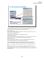
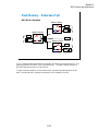
To Perform Repeat Measurements
Start (Run)
Count=0
Start Procedure
C:\Program Files\Agilent\B1500\EasyEXPERT
status=True ?
Yes
No
Count < limit
C:\Program Files\Agilent\B1500\EasyEXPERT
No
Yes
A
C:\Program Files\Agilent\B1500\EasyEXPERT
Test Execution
Count=Count+1
Iteration Procedure
No
Abort
5
status=True ?
Yes
Final Procedure
If Abort is clicked
status
limit
End
Repeat measurement is performed as shown in this flowchart. The status is a response returned by
the start/iteration procedure. The Count is the accumulated number of test executions. They are the
stop condition of the repeat measurement.
The repeat measurement stop function is enabled by the following check boxes.
•Counter reaching to
•Procedure return condition
If the first box is checked and the limit value is specified, the repeat measurement will be stopped if
Count >= limit. To perform the repeat measurement, set the limit value more than the number of
devices under test or remove check from this box.
If the second box is checked, the repeat measurement will be stopped if status = True.
When the second box is checked, the device ID automatic setup function is available and is
enabled/disabled by using the following check box. The function enters the device_id value to the
Device ID of the test result record. The device_id is a response returned by the start/iteration/subsite
procedure.
•Automatically fill in Device ID
The Repeat Measurement Setup dialog box provides the following action buttons.
•Run: Starts repeat measurement.
•Abort: Stops repeat measurement immediately.
•Cancel: Closes the Repeat Measurement Setup dialog box.
Start/Iteration/Final Procedure:
Enter the full path name of the procedure. For example, enter as follows.
C:\Program Files\Agilent\B1500\EasyEXPERT\Utilities\ProberControl\suss\Start_suss.exe
Arguments:
Enter the options of the procedure. See the following pages describing about procedures. For
example, enter –a GPIB0::5::INSTR –l C:\temp\prb.log.
If you use the sub die move operation (subsite procedure), the flowchart must be changed. See page
11-18.
11-9
Module 11
Advanced Definitions and Operations
Subsite move Test Setup
Save
Specify ProberType.
Or specify driver for your prober in
CustomProber.
Select
If you do not use the sub die (subsite) move operation, skip this page.
Click Application Test tab and open the Subsite move test setup in the Utility category. On the
Subsite move setup screen, specify ProberType (Cascade, Suss, or Vector) or driver for your prober
in CustomerProber, and save it as a setup in your preset group (My Favorite Setup). Then you can
use the setup for your quick test. See next page.
The Subsite move setup moves wafer chuck to the next subsite, reads device ID from the prober, and
sets it to the Device ID of the test result record.
For more details of the test setup, open the Test Definition window.
In the Subsite move test definition, an execution file callProbeDvr.exe is used. This file is used to
send Subsite_xxxx.exe to the prober specified by the prober_info.ini file and receive the response;
status and device_id. The callProberDvr.exe has the following input/output parameters.
Input: Full path of Subsite_xxxx.exe
Output: status; True (error) or False (no error)
Output: device_id
Note: The callProberDvr.exe refers to the prober_info.ini file for the GPIB address and log file
name. Do not set the Arguments of Subsite_xxxx.exe.
11-10
Module 11
Advanced Definitions and Operations
To Use Subsite move
C:\Program Files\Agilent\B1500\EasyEXP
C:\Program Files\Agilent\B1500\EasyEXP
C:\Program Files\Agilent\B1500\EasyEXP
5
If you do not use the sub die (subsite) move operation, skip this page.
To perform the test with the sub die move operation, do as follows.
1. Add the Subsite move test setup to your preset group (My Favorite setup).
2. Set your preset group and test setups in the Quick Test tab screen.
3. Open the Repeat Measurement Setup dialog box.
4. Specify the procedures and the repeat measurement condition.
5. Start repeat measurement.
The Subsite move setup must be entered after measurements for a sub die.
11-11
Module 11
Advanced Definitions and Operations
Prober Control Script
• Prober information file Use prober control script in EasyEXPERT
prober_info.ini
Repeat Measurement Setup window
• Start Procedure
Start_xxxx.exe
• Iteration Procedure
Iterator_xxxx.exe
• Final Procedure
Final_xxxx.exe
• Subsite Procedure
Subsite_xxxx.exe
xxxx: • cascade
• suss
• vector
Prober control script is sample program used for semi-automatic prober control. The Agilent
EasyEXPERT can call the script by using the Repeat Measurement Setup window.
See page 11-9 to call the script and perform repeat measurement.
See page 11-14 for the prober information file.
See page 11-13 for the start procedure.
See page 11-15 for the iteration procedure.
See page 11-16 for the final procedure.
See page 11-17 for the subsite procedure.
To use the prober control script, specify the start/iteration/final procedure in the Repeat Measurement
Setup dialog box (see page 11-9). And use the Subsite move test setup in your quick test to control
sub die move. The Subsite move setup uses the subsite procedure for moving wafer chuck to the
next subsite. See page 11-10 and 11-11.
11-12
Module 11
Advanced Definitions and Operations
Start_xxxx.exe
• Arguments:
Start
-a GPIB_address
-l log_file_name
Displays Device ID Entry dialog box
Example:
–a GPIB0::5::INSTR –l C:\temp\prb.log
• Response:
Updates prober_info.ini file
Displays Start Confirmation dialog box
XML format data
Moves to the first position
<Response>
<Break>status</Break>
<Target>device_id</Target>
</Response>
status:
True (error) or False
device_id:
prefix:coordinate
Prober error?
Yes
No
Gets X-Y coordinate
B
Prober error?
Yes
No
Chuck up
Example:
<Response>
<Break>False</Break>
<Target>waf1a:3 1</Target>
</Response>
Returns response
End
To specify the start procedure in the Repeat Measurement Setup dialog box, enter the full path name
of Start_xxxx.exe into the Start Procedure field.
After the repeat measurement is started, this procedure displays the Device ID Entry dialog box and
waits for your input. On the dialog box, enter a string used for the prefix of device_id. After that,
you will see the Start Confirmation dialog box that is used to confirm your wafer setup status. Load
wafer and perform wafer alignment, then click OK on the dialog box. The procedure moves wafer
chuck to the first probing position, checks the prober status, gets the X-Y coordinate of the probing
position, and sets the wafer chuck to the UP position. At last, the procedure returns the response.
The status is True or False. It is used for the EasyEXPERT repeat measurement stop function. When
the Procedure return condition box is checked in the Repeat Measurement Setup dialog box, the
repeat measurement will be stopped if status = True.
The device_id is a string for the Device ID of the test result record. When the Automatically fill in
Device ID box is checked in the Repeat Measurement Setup dialog box, the device_id will be entered
to the Device ID of the test result record.
If you use the subsite procedure, the flowchart must be changed. See page 11-18.
Note: To ignore the Arguments, set the GPIB address and log file name in the prober_info.ini.
11-13
Module 11
Advanced Definitions and Operations
Prober_info.ini
[Prober]
Address=GPIB::5::INSTR
LogMode=True
LogName=C:\temp\prb.log
[Target]
UseID=True
SubsiteInfo=False
WaferInfo=False
ID=waf1a
GPIB address of prober
Full path name of log file
device_id = prefix:coordinate
<Response>
<Break>False</Break>
<Target>waf1a:4 1</Target>
</Response>
Prefix you enter in the Device ID Entry dialog box.
ID is automatically recorded in the prober_info.ini file.
The Device ID Entry dialog box is opened by Start_xxxx.exe.
The prober information file is necessary to execute the prober control script. Before starting tests,
open this file, edit it as you want, and overwrite it. The name must be prober_info.ini.
The prober_info.ini file stores the information shown below.
•Address: GPIB address of prober
•LogMode: Log file creation mode; True or False
•LogName: Log file name (full path)
•UseID: Device ID creation mode; True or False
•SubsiteInfo: Set always False. This is just a place holder.
•WaferInfo: Set always False. This is just a place holder.
•ID: Ignore this variable. This is just a pass parameter.
If the procedures specify the –a option, the Address value is not used.
If the procedures specify the –l option, the LogName value is not used.
To create a log file, set LogMode=True.
To use the prefix:coordinate format for the device_id value, set UseID=True. If UseID=False, the
device_id value will be coordinate, not prefix:coordinate. The prefix will be the value entered in the
Device ID Entry dialog box that is opened by Start_xxxx.exe. This function is available when the
Automatically fill in Device ID check box is checked.
11-14
Module 11
Advanced Definitions and Operations
Iterator_xxxx.exe
• Arguments:
Start
-a GPIB_address
-l log_file_name
Chuck down
Example:
–a GPIB0::5::INSTR –l C:\temp\prb.log
• Response:
Prober error?
Yes
No
XML format data
Moves to the next position
<Response>
<Break>status</Break>
<Target>device_id</Target>
</Response>
B
status:
True (error) or False
device_id:
prefix:coordinate
Prober error?
Yes
No
Gets X-Y coordinate
Prober error?
Yes
No
Chuck up
Example:
<Response>
<Break>False</Break>
<Target>waf1a:4 1</Target>
</Response>
Returns response
End
To specify the iteration procedure in the Repeat Measurement Setup dialog box, enter the full path
name of Iterator_xxxx.exe into the Iteration Procedure field.
The procedure is called after the measurement is completed for a die. This procedure sets wafer
chuck to the DOWN position, moves it to the next probing position, checks the prober status, gets the
X-Y coordinate of the probing position, and sets the wafer chuck to the UP position. At last, the
procedure returns the response.
The status is True or False. It is used for the EasyEXPERT repeat measurement stop function. When
the Procedure return condition box is checked in the Repeat Measurement Setup dialog box, the
repeat measurement will be stopped if status = True.
The device_id is a string for the Device ID of the test result record. When the Automatically fill in
Device ID box is checked in the Repeat Measurement Setup dialog box, the device_id will be entered
to the Device ID of the test result record.
If you use the subsite procedure, the flowchart must be changed. See page 11-18.
Note: To ignore the Arguments, set the GPIB address and log file name in the prober_info.ini.
11-15
Module 11
Advanced Definitions and Operations
Final_xxxx.exe
• Arguments:
-a GPIB_address
-l log_file_name
Example:
–a GPIB0::5::INSTR –l C:\temp\prb.log
• Response:
none
C:\Program Files\Agilent\B1500\EasyEXP
Start
C:\Program Files\Agilent\B1500\EasyEXP
Chuck down
C:\Program Files\Agilent\B1500\EasyEXP
End
Stop condition
5
To specify the final procedure on the Repeat Measurement Setup dialog box, enter the full path name
of Final_xxxx.exe into the Final Procedure field.
The procedure is called after one of the stop condition is detected. This procedure sets wafer chuck
to the DOWN position.
Note: To ignore the Arguments, set the GPIB address and log file name in the prober_info.ini.
11-16
Module 11
Advanced Definitions and Operations
Subsite_xxxx.exe
• Arguments:
Start
-a GPIB_address
-l log_file_name
Chuck down
Example:
–a GPIB0::5::INSTR –l C:\temp\prb.log
• Response:
XML format data
<Response>
<Break>status</Break>
<Target>device_id</Target>
</Response>
status:
True (error) or False
device_id:
prefix:coordinate
Prober error?
Yes
No
Moves to the next subsite
Prober error?
Yes
No
Gets X-Y coordinate
Chuck up
Example:
<Response>
<Break>False</Break>
<Target>waf1a:3 1</Target>
</Response>
Returns response
End
To realize sub die move operation, you need to define Subsite_xxxx.exe in your test definition and
create your application test setup. However, you do not need to take care of this procedure by using
the Subsite move test setup included in the application library. The Subsite move setup moves wafer
chuck to the next subsite, reads device ID from the prober, and sets it to the Device ID of the test
result record.
Open the Subsite move test setup and save it as a setup in your preset group (My Favorite Setup).
Then you can use the setup for your quick test.
Note: To use the Subsite move setup, set the GPIB address and log file name in the prober_info.ini.
And ignore the Arguments for Subsite_xxxx.exe.
Note: If you use a Suss prober, the number of Subsite move setups used in your quick test (die test)
is important. It must be N-1; N is the number of subsites defined in the prober.
The status is True or False. It is used for the EasyEXPERT repeat measurement stop function. When
the Procedure return condition box is checked in the Repeat Measurement Setup dialog box, the
repeat measurement will be stopped if status = True.
The device_id is a string for the Device ID of the test result record.
11-17
Module 11
Advanced Definitions and Operations
To Change Execution Flow
Test Execution
A
Subsite Procedure
No
B
status=True ?
Yes
Move to the 1st subsite
If you use the subsite procedure, change the flowchart as follows.
On the page 11-9, replace the box A with the block A shown above.
On the page 11-13 and 11-15, insert the box B shown above to the position B of the flowchart.
11-18
12
Miscellaneous Operations
Module 12
Miscellaneous Operations
In This Module
•
Function Status Indicators
•
Run Option
•
Automatic Data Export and Data Record
•
Calibration
•
Configuration
•
XSLT Filters
•
To Enable System Controller
•
To Start Desktop EasyEXPERT
•
To Use 415x Setup File Converter
This module describes the above topics. You will understand what is the function status indicator,
how to change the function status, how to perform selftest and calibration, how to perform SMU zero
offset cancel, and so on.
12-2
Module 12
Miscellaneous Operations
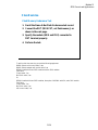
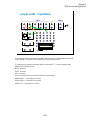
Function Status Indicators
Automatic data record ON
Automatic data export OFF
SMU zero offset cancel OFF
Standby function OFF
Multiple data display OFF
OFF
ON
ON
ON
ON
Function status indicators let you know the status OFF or ON of the following functions. The
indicators are placed at the bottom of the main screen.
Multi Display OFF/ON: Shows the multiple data display function OFF or ON status.
Standby OFF/ON: Shows the standby function OFF or ON status.
SMU Zero OFF/ON: Shows the SMU zero offset cancel function OFF or ON status.
Auto Export OFF/ON: Shows the automatic data export function OFF or ON status.
Auto Record ON/OFF: Shows the automatic data record function ON or OFF status.
Clicking indicator controls the function ON/OFF directly or opens the dialog box or window which
controls the function status.
12-3
Module 12
Miscellaneous Operations
Run Option
Auto Export and Auto Record status:
or
or
Save Data button
appears if the last
test result data is in
the memory when
both Auto Export and
Auto Record are OFF,
and allows you to save
the last data as the
test result record.
Multi data display ON
Auto Export OFF and Auto Record OFF
Multi data display OFF
Run Option button opens the Run Option dialog box used to change the status of the automatic data
record function, the automatic data export function, and the multiple data display function.
If the Record Test Result Data Automatically check box is checked, both or one of the automatic data
record function and the automatic data export function will be set to ON. To specify the function
status, see the next page.
If the Record Test Result Data Automatically check box is not checked, both functions are set to
OFF. In this status, both data record and data export are not performed. So the test execution time
will be reduced. Also, EasyEXPERT memorizes the last test result data. And it can be saved as a
test result record by clicking the Save Data button right next to the Run Option button. This status
will be useful for probe contact check, defect analysis, and so on.
The multiple data display function ON or OFF can be controlled by clicking the Multi Display
indicator or by using the Allocate Data Display for each test check box on the Run Option dialog
box.
About the multiple data display function:
If this function is OFF, the all test result data will be displayed on the singular Data Display window.
If this function is ON, the test result data of the same test setup name will be displayed on the
exclusive Data Display window and the test result data of the different test setup name will be
displayed on the new Data Display window.
12-4
Module 12
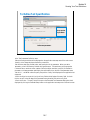
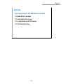
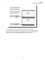
Miscellaneous Operations
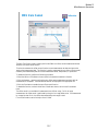
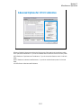
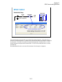
Automatic Data Export and Data Record
The automatic data export function and the automatic data record function can be enabled or disabled
by using the Test Results Data Auto Export dialog box. This dialog box is displayed by clicking
these indicators or selecting the Results > Transport Data > Auto Export Setting… menu.
The automatic data export function is used to export the test result data automatically to the storage
device you specify. You can specify the destination (storage device), exported file name, and file
type. To set the automatic data export function to enable (set to ON), check the Enable automatic
data export to the specified storage device check box.
The automatic data record function is used to save the test result data to the internal HDD
automatically. This function can be disabled if the automatic data export function is enabled. To
disable the automatic data record function, remove the check from the Enable automatic data record
to the internal storage device check box.
Even if both data export and data record functions are enabled, the functions can be set to OFF by
removing the check from the Record Test Result Data Automatically check box on the Run Option
dialog box.
12-5
Module 12
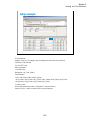
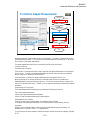
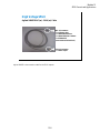
Miscellaneous Operations
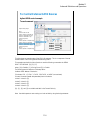
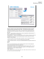
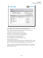
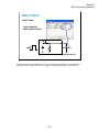
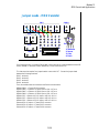
Module Self Calibration
Calibration
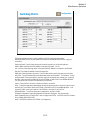
The Calibration window is opened by clicking the Calibration button. The Module Self Calibration
screen of this window is used to perform the calibration of SMUs. The list area of this screen lists
Name, Full Range, and Status.
Name: Name of module. To select, check the left check box.
Full Range: For the high resolution SMU (HRSMU) connected to the atto sense/switch unit (ASU).
Full range calibration on or off.
Status: Calibration status. Pass or fail.
Notes: Error information when calibration failed.
To perform the self-calibration, specify the modules, open the measurement terminals of the
corresponding modules, and click the Start Calibration button.
Full Range Calibration:
For the HRSMU connected to the ASU. Enables or disables the full range calibration. If this box has
been unchecked, the B1500 does not use the 1 pA range.
Enable Auto Calibration:
Enables or disables the auto-calibration capability. If this box has been checked (function ON), and
the B1500 automatically starts calibration for all modules every 30 minutes if the output switches of
all modules are off for 30 minutes.
NOTE:
To perform calibration correctly, open the measurement terminals. If auto-calibration is enabled, do
not forget to open the measurement terminals or disconnect the device under test from the terminals
after measurement.
12-6
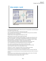
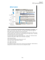
Module 12
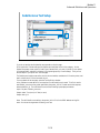
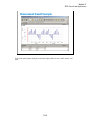
Miscellaneous Operations
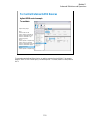
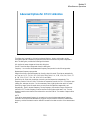
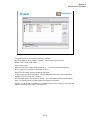
SMU Zero Cancel
Calibration
1
2
3
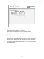
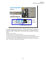
The SMU Zero Cancel screen is used to perform the SMU zero offset current measurement and set
the SMU zero offset cancel function.
This function subtracts the offset current from the current measurement raw data, and returns the
result as the measurement data. This function is used to compensate the error factor (offset current)
caused by the measurement path such as the measurement cables, manipulators, or probe card.
To enable this function, perform the following procedure.
1.Check the left box of the Name column to specify the module to enable this function.
2.Click the Measure… button to perform the zero offset current measurement and wait until the
measurement is completed. The measurement data will be displayed in the appropriate cell.
3.Click the Close button to enable the zero offset cancel function.
To disable the function, uncheck the left box of the Name column, and click the Close button.
Note:
The offset cancel is not available for measurement over 100 nA range. For 10 nA range
measurement, the offset cancel is performed by using the 1 nA range offset value. For measurement
by a range less than 10 nA, the offset value measured by each range is used.
For more information, see online help or User’s Guide.
12-7
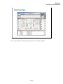
Module 12
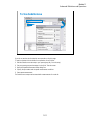
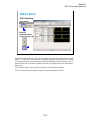
Miscellaneous Operations
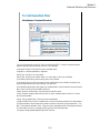
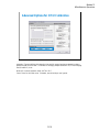
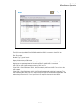
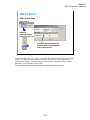
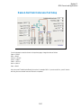
CMU Calibration
Calibration
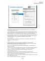
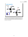
The CMU Calibration screen is used to perform the measurement data correction of the multi
frequency capacitance measurement unit (MFCMU). For the easy way, perform the phase
compensation and the open correction at least. The check boxes left of the Open/Short/Load
Correction and the Phase Compensation are effective after the corresponding measurement is
performed.
Measure…: Opens a dialog box used to perform correction/compensation data measurement. To
perform the measurement, follow the dialog box.
Advanced Options…: Opens the “Advanced Options for CMU Calibration” dialog box used to set
the frequencies for the correction data measurement and the reference values of the working
standard. See the next page.
To perform the open correction and the phase compensation, open the measurement terminals.
To perform the short correction, connect the measurement terminals together.
To perform the load correction, connect your load standard between the high terminal and the low
terminal.
NOTE:
For a more accurate measurement, perform Open/Short/Load correction at the measurement
frequency before starting the capacitance measurement.
If the measurement frequency is not included in the list of default frequencies below, click the
Advanced Options... button and set the measurement frequency on the Frequency area of the
Advanced Options for CMU Calibration window.
Default frequencies:
1 k, 2 k, 5 k, 10 k, 20 k, 50 k, 100 k, 200 k, 500 k, 1 M, 1.2 M, 1.5 M, 2 M, 2.5 M, 2.7 M, 3 M, 3.2
M, 3.5 M, 3.7 M, 4 M, 4.2 M, 4.5 M, 5 MHz
12-8
Module 12
Miscellaneous Operations
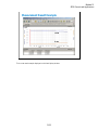
Advanced Options for CMU Calibration
This dialog box is opened by clicking the Advanced Options... button, and is used to set the
information required to measure the open/short/load correction data and the phase compensation
data. This dialog box provides the following action button.
OK: Applies the setup changes and closes this dialog box.
Cancel: Cancel the setup changes and closes this dialog box.
Frequency: You can select the measurement frequency setup mode from the following modes.
Measurement frequency setup modes:
Default (Use factory specified frequencies): Usually, select this mode. 23 points are automatically
set. They are 1 k, 2 k, 5 k, 10 k, 20 k, 50 k, 100 k, 200 k, 500 k, 1 M, 1.2 M, 1.5 M, 2 M, 2.5 M, 2.7
M, 3 M, 3.2 M, 3.5 M, 3.7 M, 4 M, 4.2 M, 4.5 M, and 5 MHz.
Specifies by list: Select this mode when you want to set the frequencies independently. The
frequency must be 1 kHz to 5 MHz. The number of frequencies must be 1 to 101. Click Add to open
a dialog box, and enter the value. For the unnecessary value, highlight the value and click Delete.
Specifies by range: Select this mode when you want to set the frequencies sequentially and
automatically. Specify the start frequency, the stop frequency, the number of steps, and the scale
LINEAR/LOG. The start frequency must be less than the Stop value and at least 1 kHz. The stop
frequency must be more than the Start value and no more than 5 MHz. The number of steps must be
2 to 1001.
NOTE:
If the device measurement frequency is not equal to the correction data measurement frequency,
calculation will be performed automatically to get the correction data for the device measurement
frequency, and the calculated correction data will be used for the data correction of the measurement
data.
12-9
Module 12
Miscellaneous Operations
Advanced Options for CMU Calibration
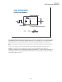
Integration Time area defines the integration time used for measuring phase compensation data or
open/short/load correction data. The number of averaging samples (Mode=AUTO) or the averaging
time (Mode=PLC) is set.
Mode: A/D converter operation mode, AUTO or PLC.
Factor: Factor for the initial value. For details, see online help or user’s guide.
12-10
Module 12
Miscellaneous Operations
Advanced Options for CMU Calibration
Reference Standard Values area provides the following entry fields used to set the reference values
of the open/short/load standard. If you use the standard, enter the reference values to the entry fields.
OPEN Reference: Capacitance and Conductance. If you do not use the reference, enter 0 in the both
fields.
SHORT Reference: Inductance and Resistance. If you do not use the reference, enter 0 in the both
fields.
LOAD Reference: Inductance and Resistance
12-11
Module 12
Miscellaneous Operations
Configuration
Main Frame
The Configuration window is opened by clicking the Configuration button, and is used to display the
system information and event log, as well as to perform diagnostics and self-test.
The Main Frame screen is used to display the system information and perform diagnostics.
Model Identification: Displays the instrument ID. B1500A.
Line Frequency: Sets the power line frequency, 50 Hz or 60 Hz.
EasyEXPERT Rev.: Displays the revision number of the EasyEXPERT.
Firmware Rev.: Displays the revision number of the B1500 firmware.
Host ID: Displays the host id of the B1500A internal computer.
Main Frame Diagnosis: This area lists Item and Status.
Item: Name of diagnostics item. To select, check the left check box.
Status: Diagnostics status. Pass or fail.
To perform diagnostics, specify the items to perform and click the Start Diagnosis button. A dialog
box is opened. Follow the dialog box to perform the diagnostics. Some items need your judgement,
pass or fail. Also you will need to connect an adapter, press keys, check LEDs, and so on.
The Host ID is important for the B1540A-002 users and the B1541A-002 users. It is necessary to
activate the EasyEXPERT or Desktop EasyEXPERT Software Plus features. For details, see the
Software Entitlement Certificate.
12-12
Module 12
Miscellaneous Operations
Configuration
Modules
The Modules screen is used to perform self-test of modules.
Slot: Slot number where the module is installed. To select, check the left check box.
Module Type: Module model number
Name: Module name
Status: Self-test status, Passed, Failed, Recovered, or ---- (self-test has not been performed)
SCUU: Specifies if the module is connected to the SCUU.
Notes: Error information when the module self-test failed.
To perform self-test, specify the modules, open the measurement terminals of the corresponding
modules, and click the Start Self Test button.
Recover Module button is for the service use only. This button makes the failed modules respond
again. This button does not solve the problem that causes the Failed status.
Status LED: Enables (ON) or disables (OFF) the status indicator (LED) of the ASU (Atto Sense and
Switch Unit) and the SCUU (SMU CMU Unify Unit).
12-13
Module 12
Miscellaneous Operations
Configuration
ASU
The ASU screen is available if the B1500A installs the HRSMU connected to the ASU (Atto
Sense/Switch Unit), and shows the ASU information.
Slot: Slot number
Module Type: Type of module
Name: Module name or SMU name
ASU Serial Number: Serial number of the ASU registered as a pair with the HRSMU. This cell
displays an error message instead of the serial number if unpaired ASU is connected.
ASU I/O Path: ASU input to output connection, SMU or AUX
If the ASU I/O Path field is set to SMU, the ASU makes the path from the ASU Force input to the
ASU output.
If the ASU I/O Path field is set to AUX, the ASU performs automatic switching in every test. The
ASU makes the path from the AUX In input to the ASU output for the test without the HRSMU and
makes the path from the ASU Force input to the ASU output for the test with the HRSMU.
12-14
Module 12
Miscellaneous Operations
Configuration
Switching Matrix
The Switching Matrix screen is used to establish the GPIB connection with Agilent
B2200A/B2201A/E5250A switching matrix and define the B2200A/B2201A/E5250A input port
connections.
Switching Matrix Type: Displays the type of the switching matrix or No Switching Matrix.
GPIB Address: Specifies the GPIB address of the switching matrix. 1 to 30.
Poll: Confirms if the switching matrix of the specified GPIB address is connected to the B1500A.
Start Self Test: Starts the selftest of the switching matrix.
SWM IN#: Switching matrix input ports. Enter the label used to specify the input port to the right
entry field. The port name and the connected module name can be the label. The character : (colon)
cannot be used. Checking the Kelvin check box grays out the coupled even number port. Checking
the CMU check box grays out SWM IN10 for the E5250A or SWM IN14 for the B2200A/B2201A.
The input ports IN11 to IN14 are not available for the E5250A.
Kelvin: Check this box if this port is used for the Kelvin connection.
CMU: To perform capacitance measurement through the switching matrix, check this check box and
set CMU1:MF to the SWM IN9 for the E5250A or the SWM IN13 for the B2200A/B2201A. And
connect MFCMU to the Input 9 and 10 of the E5250A or the Input 13 and 14 of the
B2200A/B2201A. To perform capacitance compensation, see User’s Guide.
Extended Configuration: Opens the Extended Configuration dialog box. See the next page.
Note: Standard revision of EasyEXPERT does not support the E5250. The E5250 control is a feature
of the B1540A-002/B1541A-002.
Note: The E5255A installed in the E5250A is not supported.
12-15
Module 12
Miscellaneous Operations
Extended Configuration
Configuration
This dialog box is opened by clicking the Extended Configuration button in the Configuration
window Switching Matrix screen.
Save as Hardware Profile is used to save the hardware profile that is the B2200A/B2201A/E5250A
hardware configuration and the measurement module connection. Click the Save button to save the
present hardware profile. The hardware profile can be made for each workspace individually.
CMU Compensation is used to select the compensation mode of the capacitance measurement using
the B2200A/B2201A/E5250A. Click one of the radio buttons, No Compensation, Select, and User
Compensation Data File. For the capacitance compensation, see User’s Guide.
• No Compensation:
Select this radio button if you do not need the capacitance compensation. The raw data without
compensation is displayed and saved.
• Select:
Select this radio button to perform the capacitance compensation for the path from the
B2200A/B2201A input ports to Agilent 16495F/G connector plate or Agilent B2220A probe card
interface. The data after compensation is displayed and saved.
DUT I/F field is used to specify the model number of the path you use. The selections are the
16495F/G and B2220A.
Cable field is used to specify the model number of the cable from the B2200A/B2201A output to the
DUT I/F. The selections are the 16494A/B/C-001/002/005. This mode cannot perform the
capacitance compensation for the cables to positioner/manipulator or the probe card.
• User Compensation Data File:
Select this radio button to perform the capacitance compensation for the path from the
B2200A/B2201A/E5250A input ports to the end of positioner/manipulator or probe card. See User’s
Guide. The data after compensation is displayed and saved.
Note: Standard revision of EasyEXPERT does not support the E5250. The E5250 control is a feature
of the B1540A-002/B1541A-002.
Note: The E5255A installed in the E5250A is not supported.
12-16
Module 12
Miscellaneous Operations
Configuration
SMU/PG Selector
The SMU/PG Selector screen is used to specify the input connection and the channel connection
status of the Agilent 16440A SMU/PG selector.
Enable SMU/PG Selector: Check this box to use the selector.
Selector CH1/CH2: Indicates the channels 1 and 2 of the first selector respectively.
Selector CH3/CH4: Indicates the channels 1 and 2 of the second selector respectively.
SMU Assignment: Specifies the SMU connected to the SMU input of the selector channel CH1,
CH2, CH3, or CH4.
Input/Output Path: Specifies the connection status of the selector channel CH1, CH2, CH3, or CH4.
Always SMU: Makes the selector channel “SMU on” state.
Normally PGU (AUX): Performs automatic switching in every test. The selector channel normally
makes the “PGU on” state and makes the “SMU on” state only for the test which uses the SMU
connected to the Input SMU terminal.
The CH1 and CH3 also provides the “PGU open” state which is set by using the Advanced window
of the Measurement Setup.
12-17
Module 12
Miscellaneous Operations
SMU/PG Selector
●
Easy to switch between SMU and PGU
●
Solid state relay
16440A Selector
Input SMU
Channel 1
SW1
Input PGU
SW3
Channel 2
Input SMU
To DUT
SW2
SW1
Input PGU
To DUT
SW2
SW1 & SW2 : Mechanical Relay
✓ Flash
Memory Test
photomos
SW3: Solid State Relay
✓ Transistor
The selector has two channels as shown above. Each channel has two ports (SMU and PGU).
External pulse generators can also be connected. The connectors are Triax for SMUs and outputs,
and BNC for PGUs.
Up to two selectors (four channels) may be required for some reliability tests such as Flash
EEPROM.
As a special design for Flash memory, a solid state relay was added to float the drain. This
eliminates wear and tear of millions of closures that would occur with a mechanical relay.
12-18
Module 12
Miscellaneous Operations
Configuration
Event Log
The Event Log screen displays the event log.
Date/Time: Displays date and time of the event.
Message: Event message
ID: Process ID of the event
Process: Process name
User: User name. Windows login name.
Host: Host name of the B1500
The Refresh button refreshes the event log.
12-19
Module 12
Miscellaneous Operations
XSLT Filters
Click this button
Highlight this line
The XSLT (XSL-Transformation, eXtensible Stylesheet Language Transformation) filter files are
used to export test records. The fifteen filter files listed below are stored in the
C:\Program Files\Agilent\B1500\EasyEXPERT\Utilities\XSLT folder.
The following filter files are used for exporting the measurement data only.
meas-csv.xsl, meas-tab-sv.xsl, meas-xmlss.xsl
The following filter files are used for exporting the measurement data with the index.
meas-index-csv.xsl, meas-index-tab-sv.xsl, meas-index-xmlss.xsl
The following filter files are used for exporting the measurement data with the meta data.
meas-meta-csv.xsl, meas-meta-tab-sv.xsl, meas-meta-xmlss.xsl
The following filter files are used for exporting the measurement data with the index and the meta
data.
meas-index-meta-csv.xsl, meas-index-meta-tab-sv.xsl, meas-index-meta-xmlss.xsl
The following filter files are used for exporting all data including the test setup.
csv.xsl, tab-sv.xsl, xmlss.xs
Where, the meta data contains the test name, the setup name, the record time of the test results, the
device ID, the counter number, the flag of the test results, and the remarks on the test results.
Filter files that contain xmlss in the file name export test record in the XML Spread Sheet format.
Filter files that contain csv or tab-sv in the file name use a comma or a tab for the data separator.
For more information, see online help or User’s Guide.
12-20
Module 12
Miscellaneous Operations
To Enable System Controller
Agilent IO Library Connection Expert
To control external GPIB devices, the B1500A must be set to system controller. Exit the EasyEXPERT, and
close the Start EasyEXPERT window. After that, launch the Agilent Connection Expert by clicking Start, All
Programs, Agilent IO Library Suite, and Agilent connection Expert.
On the Agilent Connection Expert, change the GPIB configuration of the B1500A.
•Select GPIB0.
•Click Change Properties… button.
•Change GPIB address to 21 that is the typical address number for the system controller.
•Check System controller box.
•Click OK button.
•Reboot the B1500A.
12-21
Module 12
Miscellaneous Operations
To Start Desktop EasyEXPERT
Database Backup Creation Wizard
Database Restoration Wizard
Important:
To set the same configuration as the B1500A,
copy the following file from B1500A to your PC.
The location must be the same.
\Documents and Settings\All Users\Application Data\Agilent Technologies, Inc\EasyEXPERT\UnitConfigB1500A.xml
To open the Start EasyEXPERT window, click Start > Programs > Start EasyEXPERT menu. This
window provides the Option menu used to open the following dialog box.
Gpib Communication:
Select Online if the B1500A, 4155B/C, or 4156B/C is connected to your computer and you want to
control it via GPIB. Or else select Offline.
Database Backup Creation Wizard:
Use this wizard to create the EasyEXPERT database backup (xdb file).
Database Restoration Wizard:
Use this wizard to restore the EasyEXPERT database backup. The wizard can restore the xdb file or
the backup which is a copy of the folder that contains the EasyEXPERT database.
EasyEXPERT Database:
Specify the EasyEXPERT Database path if you want to move the database to the other folder.
To launch Desktop EasyEXPERT, click the Start EasyEXPERT button.
Note: Desktop EasyEXPERT supports most of the EasyEXPERT functions. However, some
functions are not supported on an external computers due to differences in hardware and so on.
Note: For the installation procedure, see the readme file stored in the Desktop EasyEXPERT CDROM.
Note: For the offline mode. To use the same module configuration as the B1500A, copy the
UnitConfigB1500A.xml file to your PC which the Desktop EasyEXPERT runs. The file is stored in
the B1500A hard disk drive. The location is shown in the slide. The file must be copied to the same
location in your PC.
12-22
Module 12
Miscellaneous Operations
To Use 415x Setup File Converter
Import
4155/4156 setup file
(file extension: MES or DAT)
EasyEXPERT setup file
(file extension: XTS)
SetupFileConverter.exe
Execution example:
C:\Mydata>SetupFileConverter.exe setup1.dat
C:\Mydata>SetupFileConverter.exe *.mes
You can reuse the 4155/4156 setup file (MES file or DAT file) for the test using EasyEXPERT. This
is realized by Setup File Converter which has the function to create the XTS file by converting the
MES or DAT file to the EasyEXPERT format. This executable file is stored in the following folder.
C:\Program Files\Agilent\B1500A\EasyEXPERT\Utilities
You can execute the setup file converter on the Command Prompt as shown below. If you want to
use the Windows desktop instead of the Command Prompt, see the next page.
1. Create your working folder (for example, C:\415xdata).
2. Copy your MES or DAT files to this folder.
3. Copy SetupFileConverter.exe file to this folder.
4. Launch the Command Prompt.
5. Go to your working folder (for example, C:\> cd 415xdata).
6. Execute SetupFileConverter.exe as shown in the following example.
C:\415xdata> SetupFileConverter.exe *.MES
This example converts all MES files in your working folder to the EasyEXPERT setup file format,
and creates the XTS files in this folder.
Note: If you execute the setup file converter without the parameter, the help message will be
displayed.
Note: The setup file converter provides some options. See User’s Guide or online help for the
options.
12-23
Module 12
Miscellaneous Operations
To Use 415x Setup File Converter
1. Drag and drop the shortcuts of the MES/DAT file on
the shortcut of the Setup File Converter.
3. XTS file and shortcut are created.
2. File conversion is executed and system message is displayed.
You can perform the file conversion on the Windows desktop as follows.
1. Create a shortcut of the SetupFileConverter.exe on the desktop.
2. Copy your MES/DAT files to the desktop.
3. Drag and drop the shortcuts of the MES/DAT files on the shortcut of SetupFileConverter.
This starts the file conversion and displays the system message. And if the conversion is completed
successfully, the setup file converter creates the XTS files and the shortcuts on the desktop.
Note: The setup file converter provides some options. See User’s Guide or online help for the
options.
12-24
Module 12
Miscellaneous Operations
To Use 415x Setup File Converter
Click [Start] → All Programs → Agilent B1500A EasyEXPERT
→ 4155,4156 Setup File Converter
To create XTS file:
The following procedure converts the 4155/4156 setup file (.DAT or .MES) and creates the .XTS file
in the folder the setup file is stored.
1. Click Select icon, or click File > Select Files to open the Select 4155/4156 MES Files or DAT
Files dialog box.
2. Specify the 4155/4156 setup files to convert. Multiple files can be selected.
3. Click Open on the Select 4155/4156 MES Files or DAT Files dialog box.
4. Click Convert icon, or click File > Convert Files.
To read XTS file, use the import function to read the created .XTS file on the EasyEXPERT.
12-25
Module 12
Miscellaneous Operations
12-26
13
SPGU Control and Applications
Module 13
SPGU Control and Applications
In This Module
•
High Voltage SPGU
•
SPGU Control
•
Pulse Generator Mode
•
Charge Pumping
•
Flash Memory Test
•
ALWG Mode
13-2
Module 13
SPGU Control and Applications
High Voltage SPGU
High Voltage Semiconductor Pulse Generator Unit
z
z
z
z
z
z
z
z
2 channels per module
Output impedance: 50 ohm
Amplitude: +/-40 V (open load), +/-20 V (50 ohm load)
PG mode or ALWG mode
Free run, duration, or count
2- or 3-level pulse output for each channel in PG mode
Pulse switch
Automatic voltage level adjustment
50 ohm
Pulse switch
3-level voltage pulse
ALWG voltage
SPGU
OUT
✓ Charge
Pumping
Memory Test
✓ AC Stress
✓ Flash
High Voltage Semiconductor Pulse Generator Unit (HVSPGU) is specially designed for
semiconductor test. Most pulse generators' output voltage is less than 10 V with 50 ohm impedance.
However, in semiconductor test (especially reliability test) 30 to 40 V capability is required for the
flash memory write/erase cycle test. The HVSPGU output voltage is 40 V at open load.
The HVSPGU provides two output mode, PG mode and ALWG mode. In the PG mode, the
HVSPGU can output 2- or 3-level voltage pulse. And in the ALWG mode, it can output an arbitrary
linear waveform voltage.
The pulse switch is built into the SPGU channel for performing the endurance test of the NOR type
flash memory effectively. The SPGU channel can output the drain pulse for the write operation and
make the open status for the erase operation in one pulse period.
The output impedance of the SPGU is fixed to 50 ohm. However, the SPGU channel can output the
voltage close to the setting value if you specify the load impedance of DUT properly. Because the
channel automatically adjusts the output level by using the specified load impedance value.
13-3
Module 13
SPGU Control and Applications
High Voltage SPGU
Rear View
Connect 16493Q cables to make
synchronization of multiple SPGUs.
Max. 5 Modules (10 output channels)
PG3 PG4
PG1 PG2
Slot 2 (Slave SPGU)
Slot 1 (Master SPGU)
LED to show the output switch status
The B1500A can install the maximum of five SPGUs. The SPGUs must be installed in the contiguous slots
from the slot 1. Where the SPGU installed in the slot 1 is the master SPGU. The channel number PG1 is
assigned for the Output 1 of the master SPGU. And the following numbers are assigned for the subsequent
channels.
The SPGU has seven connectors.
The Output connectors are for the SPGU signal output.
The Ref In/Out and Sync In/Out connectors are for making synchronization of multiple modules.
The Trig Out connector outputs the trigger signal used to make synchronization with the external instruments.
If the multiple SPGU modules are installed, the 16493Q cables must be connected between the Ref Out
connector and the Ref In connector and between the Sync Out connector and the Sync In connector as shown
above. This is necessary to synchronize the module outputs.
13-4
Module 13
SPGU Control and Applications
High Voltage SPGU
Pulse Switch
CLOSE
Write
Erase
Drain
CLOSE
Substrate
Gate
OPEN
SMU
Source
Drain
SMU
CLOSE
Pulse period
Substrate
Gate
OPEN
SMU
Source
SMU
Write Erase
The pulse switch is the built-in high speed analog switch to open/close the SPGU output for each
channel. This switch is used in the write/erase cycle of the NOR type flash memory cell test. This
dramatically improves throughput of the endurance test (write/erase lifetime reliability test). The
SPGU channel can output the drain pulse for the write operation and make the open status for the
erase operation in one pulse period.
13-5
Module 13
SPGU Control and Applications
High Voltage SPGU
Effects of Load Impedance
Output Impedance
50 Ω
Vset
V
Pulse Source
Vdut
Rdut
Vset: Setting voltage with open load
Vdut = Vset ×
Rdut
Rdut + 50
The voltage actually applied to the DUT depends on it’s impedance. This behavior is very common among the
instrumentations like DC power supply and pulse generators. In this meaning, SMU is very special because
the output of SMU is controlled by the feedback loop from the voltage monitored by the sense terminal.
If Rdut is large enough (ex. gate terminal) compared with 50 ohm output impedance, Vdut is almost equal to
Vset.
If Rdut is not so large (ex. drain terminal at the ON state), the difference between Vdut and Vset is not
negligible. In the case of 1 mA current with 1 V bias (= 1 kohm), the difference will be about 5 %.
The SPGU provides the function to adjust the output voltage automatically. To use this function properly, the
load impedance of DUT must be registered and it must be accurate. Then the SPGU can apply the voltage
near the setting value to the DUT.
13-6
Module 13
SPGU Control and Applications
High Voltage SPGU
Effects of Load Impedance
Mismatch of load impedance
setting may cause the error of
applied voltage to the DUT.
Actual
Expected
Setup: 1V output, 50 Ω load
Actual load: 1 MΩ Æ 2 V output
Expected
Actual
Setup: 1 V output, 1 MΩ load
Actual load: 50 Ω Æ 0.5 V output
Here is the example of the voltage error due to the mismatch of the load impedance setting.
If the load impedance is set to 50 ohm when the actual load impedance is 1 Mohm, the voltage actually applied
to the DUT is about double the setting value. If the load impedance is set to 1 Mohm when the actual load
impedance is 50 ohm, the voltage actually applied to the DUT is about half the setting value. So the load
impedance value must be accurate to apply the voltage near the setting value to the DUT.
13-7
Module 13
SPGU Control and Applications
High Voltage SPGU
Agilent 16493P BNC (m) - SMA (m) Cable
BNC (m) connector:
• To connector plate
• To 16442A/B test fixture
• To 16440A SMU/PGU selector
• To E5288A ASU
(Atto Sense and Switch Unit )
SMA (m) connector:
• To SPGU output
Agilent 16493P is the connection cable for the SPGU outputs.
13-8
Module 13
SPGU Control and Applications
SPGU Control
Mode: VPULSE or ALWG
Check here to display the Percent of Progress vs. Time plot.
Check here to display the Time data list.
The SPGU can be used in the classic test other than the C-V Sweep and the Switching Matrix
Control. So you can use the SPGU output while a measurement is performed. If you need the SPGU
output only, use the SPGU Control classic test. In this classic test, the single button triggers the
SPGU outputs, and the Data Display works as the progress monitor.
The SPGU provides two output mode, VPULSE (pulse generator mode) and ALWG (arbitrary linear
waveform generator mode). And the same mode must be set to the all output channels. The B1500A
can have the maximum of ten SPGU output channels.
The Advanced button opens the Advanced Setup dialog box. The dialog box is used to set the after
measurement settings and the 16440A selector semiconductor relay setting.
After Measurement Setting:
•Bias Hold after Measurement: Bias hold function ON or OFF.
Semiconductor Relays (16440A SMU/PG Selector):
•CH1: Default or PGU OPEN
•CH3: Default or PGU OPEN
The fields define the selector channel’s switch condition during the measurement. Default means the
setting defined on the SMU/PG Selector screen of the Configuration window.
13-9
Module 13
SPGU Control and Applications
SPGU Control
SPGU Pulse Setup
SPGU Control
Buttons on
Measurement Setup
screen of a Classic Test
If the SPGU output mode is set to VPULSE, the Pulse/ALWG button opens the SPGU Pulse Setup
window. This window is used to define the voltage pulses applied by the specified SPGU channels.
For the setup parameters, see later page titled Pulse Setup Parameters of Pulse Generator Mode. In
the other classic test, this window is opened by the SPGU Pulse Setup button on the Measurement
Setup screen.
The Pulse Switch button opens the dialog box used to set the pulse switch operation.
The Load Z button opens the dialog box used to set the load impedance of the DUT.
13-10
Module 13
SPGU Control and Applications
SPGU Control
Pulse Switch Setup
50 ohm
Pulse period
Pulse switch
SPGU
OUT
Delay Width
3-level voltage pulse
Write
OPEN
Erase
Default setting of the switch is “CLOSE”
You can set the pulse switch operation on the Pulse Switch Setup dialog box. Set the SW Sync to
ENABLE to use the pulse switch. The delay time is the time from start of pulse output to changeover
of pulse switch. The width is the duration to hold the switched state of the pulse switch. And the
normal field specifies the pulse switch status OPEN or CLOSE at the normal state which is not the
switched state.
Recommended width value is more than 100 us because of the time lag for changeover.
13-11
Module 13
SPGU Control and Applications
SPGU Control
Load Z Setup
Output Impedance
Setting (default=50 ohm)
50 Ω
Vset
V
Vdut
Rdut
Vset: Setting voltage with open load
You can specify the load impedance of DUT on the Load Z Setup dialog box. By setting the load
impedance value accurately, the SPGU can apply the voltage near the setting value to the DUT.
13-12
Module 13
SPGU Control and Applications
SPGU Control
SPGU ALWG Setup
SPGU Control
Buttons on
Measurement Setup
screen of a Classic Test
This button opens the Define ALWG
Waveform window used to define the
ALWG output sequence.
If the SPGU output mode is set to ALWG, the Pulse/ALWG button opens the SPGU ALWG Setup
window. This window is used to define the arbitrary linear waveform voltage applied by the
specified SPGU channels. In the other classic test, this window is opened by the SPGU ALWG
Setup button on the Measurement Setup screen.
The Load Z button opens the dialog box used to set the load impedance of the DUT.
13-13
Module 13
SPGU Control and Applications
Pulse Generator Mode
Pulse Setup Parameters
Pulse period
Pulse width
Leading time
Trailing time
Pulse peak
90 %
Amplitude
10 %
Pulse base
Delay time
The pulse setup parameters are defined as shown above.
The pulse leading time and trailing time are defined as the voltage transition time between 10 % and
90 % of the amplitude. Minimum setting value is 8 ns.
13-14
Module 13
SPGU Control and Applications
Pulse Generator Mode
Pulse output example:
2. SPGU Pulse Setup window
Pulse period
3. Pulse setup parameters
To apply the SPGU pulse output, set the pulse setup parameters, specify the Operation, and click the
Single button.
The following operations are available.
PULSE COUNT: SPGU outputs the specified number of pulses. Specify a number within the range
of 1 to 1000000.
DURATION: SPGU continues the output until the specified time elapses. Specify a time within the
range of 1 us to 31556926 s (1 year).
FREE RUN: SPGU continues the output until the measurement is completed or stopped. This
operation is not available for the SPGU Control classic test.
To set the pulse setup parameters,
1. Display the SPGU Control classic test screen or the Measurement Setup screen of the other classic
test.
2. Open the SPGU Pulse Setup window by clicking the Pulse/ALWG button on the SPGU Control
classic test screen or the SPGU Pulse Setup button on the Measurement Setup screen.
3. Set the Type, Period, and Primary Pulse parameters. For the pulse setup parameters, see the
previous page.
For the 3-level pulse, select the 3-Level Pulse type. Then the Additional Pulse fields will be active.
The 3-level pulse is defined as sum of two 2-level pulses, Primary Pulse and Additional Pulse.
13-15
Module 13
SPGU Control and Applications
Pulse Generator Mode
3-Level Pulses
•
Every channel can output 3-level pulse
80 Vp-p within +/-40 V window (at open load)
•
Pulse width and level of each channel can be set individually.
SPGU10
+40V
80Vpp
SPGU3
SPGU2
-40V
SPGU1
Up to 10 output channels can be installed in one B1500A and each channel can output 3-level pulse with a
maximum output voltage.
The channels are independent. So the channels can apply the different pulses. However, the pulse period
value is common for all channels.
13-16
Module 13
SPGU Control and Applications
Charge Pumping
Gate
Source
n+
Drain
Oxide
n+
p
or
A
Substrate
A
SMU
PGU
Icp
SMU
Charge pumping is a type of hot carrier measurement. It provides direct measurement of interface
states and an indication of electron and hole trapping.
The gate of the MOS transistor is connected to a pulse generator. The current (Icp) is caused by the
repetitive recombination of minority carriers with majority carriers at the silicon-silicon oxide
interface.
13-17
Module 13
SPGU Control and Applications
Charge Pumping
Three Methods of Charge Pumping
Gate Waveforms
Voltage
Square Pulse
Triangle Pulse
Trapezoidal Pulse
Time
Square Pulse
The base of the pulse is stepped from well below gate threshold to well above. At each step, the
substrate leakage current is monitored. The flat part of the resultant curve is proportional to
interface-state density.
Triangle Pulse
The frequency of a constant height triangle pulse is increased in steps. At each step, substrate
leakage is measured. Average interface state density and capture cross-section are measured by this
method.
Trapezoidal Pulse
A fixed height pulse is applied to the gate. By varying the leading/trailing edge of the pulse, you can
plot interface-state density vs energy.
13-18
Module 13
SPGU Control and Applications
Charge Pumping
Start
Calculates Vbase
&
Sets meas. parameters
to I_sub sampling test
I_sub sampling meas.
by applying Vg pulse
Records Isub and Vbase
More Vbase?
Y
Looping of classic test for each
base step of Gate pulse.
N
Calculates IcpMax & NSS
Plots Icp vs Vbase
Icp is measured after each increment of the gate pulse base value. A curve of Icp vs base value is
plotted. The maximum Icp value is noted. At this point:
Icp = f * Qss
= f * Ag * q * Dit
where
f: pulse frequency
Qss: recombined charge per pulse period
Aq: channel area of the transistor
q: electron charge
Dit: interface state density
13-19
Module 13
SPGU Control and Applications
Class Exercise
Square Pulse Charge Pumping
1. Recall the Charge Pumping 4T 0.1V step test record.
2. Connect the DUT (MOS FET) as shown in the next
page.
3. Specify the module (SMU and PGU) connected to
DUT terminal properly.
4. Perform the test.
Note:
13-20
Module 13
SPGU Control and Applications
Jumper Leads – MOS transistor
F
1
F
G
F
2
PGU
F
PG1
1
1
VSU
VMU
SMU
F
4
G
G
G
1
F
3
F
5
F
G
GNDU
6
F
S
G
2
2
2
1
2
3
4
5
6
7
8
9
10
11
12
13
14
15
16
17
18
19
20
21
22
23
24
28
15
25
26
27
28
14
1
S
D
G
Sub
1: Substrate
2: Source
3: Gate
4: Drain
For all class exercises, you need the 28-pin dual in line socket which comes standard with the 4145
fixture (16058A) or the newer fixture (16442A/B). Either fixture works fine.
This class exercise requires four jumper leads to connect the DUT. Connect the jumper leads
between the following terminals.
SMU1 : terminal 1
SMU2 : terminal 2
SMU4 : terminal 4
PGU1 : terminal 3
Then, the modules must be connected to the fixture as shown below.
B1500A SMU1 -> Fixture SMU1 connector
B1500A SMU2 -> Fixture SMU2 connector
B1500A SMU4 -> Fixture SMU4 connector
B1500A PG1 -> Fixture PGU1 connector
13-21
Module 13
SPGU Control and Applications
Measurement Result Example
Here we see the result of plotting Icp vs pulse base voltage.
13-22
Module 13
SPGU Control and Applications
Flash Memory
Basic Flash memory Cell Structure
VCG
Control gate
Id
Write
Erase
(discharged) (Qf is injected)
Floating node
Vd
C2
C3
Qf
C0
Delta Vg
C1
Source
Drain
VCG
Voltage for Write/Erase judgment
Bulk
Qf is injected (by a pulse) to
write the memory
Effective gate voltage shifts Delta Vg = Qf/Cf.
Cf is effective floating gate capacitance.
Flash memory is one type of floating gate memory. The left figure shows the structure of the floating
gate memory cell. There is a metal floating node on the top of transistor channel region. Any stored
charge in this floating node shifts its threshold voltage as shown in the right figure.
13-23
Module 13
SPGU Control and Applications
Flash Memory – Endurance Test
1 million Write/Erase cycle test
Start
Initial Write/Erase Test
Next burst test
End
Vth (V)
T
i <= 10^6
F
Burst Write/Erase Test
Write/
Program
Write
Measure Vth (*1)
Erase
Measure Vth (*2)
Erase
(*1) Id(on) and Id(off)
are measured as well.
(*2) Id(on), Id(off) and
sub-threshold swing (Sfactor) are measured as
well.
0
10
1
10
2
10
3
4
10 10
Cycles
5
10
6
10
Endurance test is a kind of reliability tests. Repetitive write (program) and erase pulses are applied
to the cell and the Vth of the cell is monitored after certain number of pulses are applied. This test
is important because the flash memory is used for the data and file storage application. Then the
failure rate must be less than one percent for one million write/erase cycles. Therefore, for device
development, the endurance test is the critical test to make sure that the durability of the cell can
meet the target.
When measuring characteristics after certain number of write-erase cycling, Id(on) and Id(off) are
measured besides Vth depending on the cell type. In case of the cell types which use the F-N
tunneling between substrate and floating gate, sub-threshold swing is also measured after erasing
the cell.
13-24
Module 13
SPGU Control and Applications
Flash Memory – Endurance Test
NAND Cell Test
• Burst write/erase reduces
test time dramatically
Write pulse
SPGU output
Gate
40V
Drain
-40V
In an example, the test time was less
Source
than 2 hours for 1 million cycle test.
Sub
It will be about 1/70 compared with
3-level pulse by each channel
Erase pulse
4155/4156 solution.
Write pulses
Open
NOR Cell Test
• Drain open can be made by
opening the analog switch in
the HVSPGU.
SPGU
Gate
Drain
For 1 million cycle test, 2PG solution
improves the test time about 1/4
Source
compared with 4155/4156 solution.
Sub
3PG solution improves it about 1/4
compared with 2PG solution.
Pulse switch for drain open
Note:
13-25
12V
7V
12V
Erase pulse
Module 13
SPGU Control and Applications
Flash Memory – Endurance Test
NOR Write Connection
Selector or ASU ch3
Mech
Solid Mech
State
Selector or ASU ch2
SMU3
Drain
Mech
Mech
Gate
Source
PG4
SMU1
Substrate
PG3
SMU4
Selector or ASU ch1
Mech
Solid Mech
State
SMU2
PG2
This is an example setup to perform the write operation of the NOR type flash memory cell. This
setup uses three sets of the SMU, SPGU, and selector/ASU. This setup is used by the Demo-SNorFlash Endurance test shown in Class Exercise.
To perform the write operation, all of the selector/ASU channels must make the path to the PG.
Note: The solid state relay is installed in the selector, but not installed in the ASU.
13-26
Module 13
SPGU Control and Applications
Flash Memory – Endurance Test
NOR Erase Connection
Selector or ASU ch3
Mech
Solid Mech
State
Selector or ASU ch2
SMU3
Drain
Mech
Mech
Gate
Source
PG4
SMU1
Substrate
PG3
SMU4
Selector or ASU ch1
Mech
Solid Mech
State
SMU2
PG2
This is an example setup to perform the erase operation of the NOR type flash memory cell. To
perform the erase operation, all of the selector/ASU channels must make the path to the PG and the
PG3 internal pulse switch must be opened. The pulse switch is also a solid state relay.
Note that the solid state relay in the selector is not used. The relay must be always close.
13-27
Module 13
SPGU Control and Applications
Flash Memory – Endurance Test
Measure Vth Connection
Selector or ASU ch3
Mech
Solid Mech
State
Selector or ASU ch2
SMU3
Drain
Mech
Mech
Gate
Source
PG4
SMU1
Substrate
PG3
SMU4
Selector or ASU ch1
Mech
Solid Mech
State
SMU2
PG2
Vth must be measured after writing or erasing. To perform the Vth measurement, all of the
selector/ASU channels must make the path to the SMU. Vth is measured at each decade, so a
mechanical relay will be used, not the solid state relay. The mechanical relay has low leakage
specifications to better match the capabilities of the SMUs.
13-28
Module 13
SPGU Control and Applications
Class Exercise
Flash Memory Endurance Test
1. Recall the Demo-S-NorFlash Endurance test record.
2. Connect the DUT (MOS FET, not flash memory) as
shown in the next page.
3. Specify the module (SMU and PGU) connected to
DUT terminal properly.
4. Perform the test.
To perform this class exercise, you need the following equipment.
16440A Selector with control cable, 2 sets
16445A Selector adapter with control cable, 1 set
B1500A installed with two SPGU modules and four SMU modules
Test fixture
Triaxial cable, 7 ea.
BNC-SMA cable, 3 ea.
Or,
B1500A installed with two SPGU modules, three pairs of HRSMU and ASU, and a SMU module
Test fixture
Triaxial cable, 7 ea.
BNC-SMA cable, 3 ea.
ASU control cable, 3 ea.
13-29
Module 13
SPGU Control and Applications
Jumper Leads – MOS transistor
F
1
F
G
F
2
1
1
PGU
F
VSU
VMU
SMU
F
4
G
G
G
1
F
3
F
5
F
G
GNDU
6
F
S
G
2
2
2
1
2
3
4
5
6
7
8
9
10
11
12
13
14
15
16
17
18
19
20
21
22
23
24
28
15
25
26
27
28
14
1
S
D
G
Sub
1: Substrate
2: Source
3: Gate
4: Drain
For all class exercises, you need the 28-pin dual in line socket which comes standard with the 4145
fixture (16058A) or the newer fixture (16442A/B). Either fixture works fine.
This class exercise requires four jumper leads to connect the DUT. Connect the jumper leads
between the following terminals.
SMU1 : terminal 1
SMU2 : terminal 2
SMU3 : terminal 3
SMU4 : terminal 4
Then, the modules must be connected to the fixture as shown below.
B1500A SMU1 -> Fixture SMU1 connector
B1500A SMU2 -> Selector ch1 SMU input or ASU ch1 Force
B1500A SMU3 -> Selector ch2 SMU input or ASU ch2 Force
B1500A SMU4 -> Selector ch3 SMU input or ASU ch3 Force
B1500A PG2 -> Selector ch1 PGU input or ASU ch1 AUX In
B1500A PG3 -> Selector ch2 PGU input or ASU ch2 AUX In
B1500A PG4 -> Selector ch3 PGU input or ASU ch3 AUX In
Selector/ASU ch1 output -> Fixture SMU2 connector
Selector/ASU ch2 output -> Fixture SMU3 connector
Selector/ASU ch3 output -> Fixture SMU4 connector
13-30
Module 13
SPGU Control and Applications
Demo-S-NorFlash Endurance Test Setup
For the instrument connection shown in the previous pages, change the value as follows.
Pgate -> SPGU3
Gate -> SMU3
Psource -> SPGU2
Source -> SMU2
Pdrain -> SPGU4
Drain -> SMU4
Subs -> SMU1
Also, set a small TotalWriteAndEraseCycles value, for example 1000. If you set one million, you will have to
wait long time over several hours until the test is completed.
13-31
Module 13
SPGU Control and Applications
Measurement Result Example
Write
Erase
This is a test result example displayed on the Data Display window.
13-32
Module 13
SPGU Control and Applications
ALWG Mode
Specify number of repeat for each pattern group.
50 ns
50 ns
PG1 Output
Pattern 1
Pattern 2
Pattern N
Smooth Transition!
No Glitch , No dip to
GND.
Δt
PG2 Output
Pattern 3
Pattern 4
Pattern X
Must be < (1,024 - # of Patterns) points
for each channel
ALWG stands for Arbitrary Linear Waveform Generator. This function is similar to the AWG (Arbitrary
Waveform Generator), but specialized for a semiconductor parametric test. The ALWG describes the pulse
wave by the combination of the line segment described as the differential time and absolute voltage.
Key features are as follows.
•Number of patterns in a sequence: maximum 512 for a channel
•Number of vector data: maximum 1024-N (N: number of patterns) for defining all patterns to a
channel
•Repeat count of a pattern group: maximum 1,048,576
•Time data (differential time, delta T): 10 ns to 671.088630 ms with 10 ns resolution
•Extremely short over head, 50 ns to change the pattern. No delay for the repetition of the same
pattern.
Of course, +/-40 V and 80 Vpp feature of HVSPGU is available with this ALWG feature.
This function allows you to use more complicated waveform like the multiple level pulse more than 3-level,
and step pulse or ramp voltage to characterize the novel flash memory like CTF.
13-33
Module 13
SPGU Control and Applications
ALWG Mode
1. SPGU ALWG Setup Window
Count
Pattern
Open
This button opens the Pattern Editor
used to define the arbitrary linear
waveform.
2. Define ALWG Waveform window
To apply the ALWG output, define the ALWG output sequence, specify the Operation, and click the
Single button.
The following operations are available.
PULSE COUNT: SPGU outputs the specified number of sequences. Specify a number within the
range of 1 to 1000000.
DURATION: SPGU continues the output until the specified time elapses. Specify a time within the
range of 1 us to 31556926 s (1 year).
FREE RUN: SPGU continues the output until the measurement is completed or stopped. This
operation is not available for the SPGU Control classic test.
To define the ALWG output sequence,
1. Open the SPGU ALWG Setup window by clicking the Pulse/ALWG button on the SPGU Control
classic test screen or the SPGU ALWG Setup button on the Measurement Setup screen of the other
classic test.
2. Open the Define ALWG Waveform window by clicking the button of the ALWG Source on the
SPGU ALWG Setup window.
The ALWG output sequence can be defined by specifying the waveform pattern and the repeat count
on the Define ALWG Waveform window. To create a new waveform pattern, use the Pattern Editor.
See the next page.
13-34
Module 13
SPGU Control and Applications
ALWG Mode
A pattern can be defined by specifying the differential time and the absolute voltage. You can define
it by using the left side GUI or the right side table on the window.
13-35
Module 13
SPGU Control and Applications
Class Exercise
Monitor ALWG output by the sampling measurement.
1. Click I/V-t Sampling icon and open setup editor.
2. Define the measurement setup with the ALWG
output.
3. Save the test setup.
4. Connect a device (511 kohm resistor) as shown in the
next page.
5. Perform the test.
Channel Setup:
SMU1 -> V1, I1, Mode=I
SMU2 -> V2, I2, Mode=COMMON
SPGU1 -> SPGUV1, Mode=ALWG
Measurement Setup:
Interval=2 ms
No of Samples=201
SMU1 -> Source=0 A, Compliance=2 V
Range:
SMU1 -> Mode=FIXED, Range=2 V
ADC/Integ:
SMU1 -> ADC=HS ADC
Advanced:
SMU1 -> SMU Filter=OFF
SPGU ALWG Setup:
SPGU1 -> LoadZ=511 kohm
ALWG Source -> Define the waveform as you like.
Display Setup:
X-axis -> Time
Y1-axis -> V1
For the example setup, open the “ALWG monitor” test setup.
13-36
Module 13
SPGU Control and Applications
Jumper Leads – Capacitance
F
1
F
G
2
PGU
F
PG1
1
1
F
VSU
VMU
SMU
F
4
G
G
G
1
F
3
F
5
F
G
GNDU
6
F
S
G
2
2
2
4
5
6
9
10
11
12
14
15
16
17
18
20
21
22
23
1
2
7
8
13
19
28
3
15
24
25
26
27
28
14
1
511 kohm
For all class exercises, you need the 28-pin dual in line socket which comes standard with the 4145
fixture (16058A) or the newer fixture (16442A/B). Either fixture works fine.
This class exercise requires three jumper leads to connect the DUT. Connect the jumper leads
between the following terminals.
SMU1 : terminal 1
SMU2 : terminal 4
PGU1 : terminal 1
Then, the modules must be connected to the fixture as shown below.
B1500A SMU1 -> Fixture SMU1 connector
B1500A SMU2 -> Fixture SMU2 connector
B1500A PG1 -> Fixture PGU1 connector
13-37
Module 13
SPGU Control and Applications
Measurement Result Example
This is a test result example displayed on the Data Display window for the “ALWG monitor” test
setup.
13-38