1
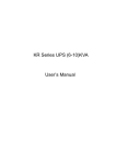
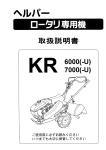
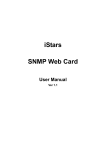
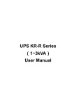
UPS KR-R Series (6-10kVA) User’s Manual 【NOTE】 Please carefully read the user’s manual before operation for the sake of understanding correct operation of the instrument. Please keep the manual handy for future reference. WARNING The input and output of the instrument is with dangerous high voltages which may endanger the safety of life. Please strictly follow the operating description.It is not allowed to remove the cover of the instrument. 1. Please connect protective earth before power supply cables. 2. The input & output voltage of the UPS is dangerous which will endanger the safety. 3. Dangerous voltages are present inside the unit. Please do not open the cover of the UPS. 4. Please turn off the mains input switch and the battery switch for any urgency. 5. There are many kinds of power sources in the equipment, the terminal or socket may still have dangerous voltage even if the main power is disconnected. 6. Please remove the cable between the battery & UPS before repairing. It’s necessary to wait for another 5 minutes for discharging, because of the dangerous voltages. 7. The wires should be fastened to the terminals. It is prohibited to short the anode and cathode of battery. It’s prohibited to touch any two of wire connectors or bare end of connecting wires. Otherwise, it may lead to damage of battery or personal injury. 8. Please keep the battery away from the fire and all the equipment that may cause spark to prevent the danger and damage. 9. Please do not open or shatter the battery, the overflow electrolyte is with causticity that may be harmful to life. 10. Please contact the professional personnel of the local dealer or the special maintenance station for any trouble-shooting. Random disposal of the trouble is not allowed. 11. This is an A-grade product with electromagnetic compatibility. 12. This equipment must be installed and serviced by qualified personnel. 13. Before usage, confirm that the temperature of the instrument has dropped into the normal run range. It is recommended still placement for 24 hours in the normal temperature range before startup. 14. Before you replace the battery of different brand and different type, make sure the charging voltage is matching with UPS charging voltage due to the different required charging voltage of different battery, If any doubt, please consult with the manufacturer. Any changes of the system configuration, structure and composition will influence the performance of UPS, please consult with the manufacturer in prior before doing any changes. Product Standard:Q/ZZKJ001 Index 1. Overview................................................................................................................................... 1 1.1 Model Meaning Explanation .............................................................................................. 1 1.2 Brief Introduction ............................................................................................................... 1 1.2.1 Products Characteristics ......................................................................................... 1 1.2.2Technical Specification ............................................................................................ 3 2. Basic Principle and Structure ................................................................................................. 4 2.1 Stand-alone Principle ........................................................................................................ 4 2.1.1 Principle Diagram .................................................................................................... 4 2.1.2 Principle .................................................................................................................. 4 2.1.3 Work Process.......................................................................................................... 4 2.2 Structure ........................................................................................................................... 6 2.2.1 KR-J Series (6&10KVA) Display Interface ............................................................... 6 2.2.2 Structure and Appearance ...................................................................................... 7 3. Installation ................................................................................................................................ 9 3.1 Installation Notice.............................................................................................................. 9 3.2 Installation Steps ............................................................................................................... 9 3.3 Preparing for Installation ................................................................................................. 10 3.3.1 Check the Installation Site ..................................................................................... 10 3.3.3.1 Environment Requirement .................................................................................. 10 3.3.1.2 The Basic Requirements for Power Supply ........................................................ 10 3.3.2 Unpacking and Inspection ..................................................................................... 11 3.3.2.1 Transportation .................................................................................................... 11 3.3.2.2 Unpacking .......................................................................................................... 11 3.4 Equipment Installation ..................................................................................................... 12 3.5 Check the Main Input ...................................................................................................... 12 3.6 Battery Cabinet Installation ............................................................................................. 12 3.6.1 Important Safety Rules .......................................................................................... 13 3.6.2 Installation step ..................................................................................................... 13 3.7 (Parallel) System Installation ........................................................................................... 13 3.8 Electrical Connection ...................................................................................................... 14 3.8.1 Wire Modes of Single UPS .................................................................................... 14 3.8.2 Connecting Way of Parallel System ...................................................................... 14 3.9 System Inspection and Testing ....................................................................................... 15 3.9.1 Check Electrical Connections ................................................................................ 15 3.9.2 UPS Testing .......................................................................................................... 16 3.9.3 Connect with the load ............................................................................................ 16 4. Operation................................................................................................................................ 17 4.1 Notes of Using UPS ........................................................................................................ 17 4.2 UPS Single Unit Operation Process ................................................................................ 17 4.3 Operation Instruction ....................................................................................................... 17 4.3.1 Inspection before Power on ................................................................................... 17 4.3.2 UPS Switch-on Procedure ..................................................................................... 18 4.3.3 Start the load ........................................................................................................ 18 4.3.4 UPS Switch-off Procedure ..................................................................................... 19 4.4 Operating procedure of Parallel System .......................................................................... 19 4.4.1 Parallel System Start-up........................................................................................ 19 4.4.2 Parallel System Shut Down ................................................................................... 19 4.4.3 Online Shutdown Parallel System ......................................................................... 20 4.4.4 Online Start-up Parallel System ............................................................................ 20 4.4.5 Redundancy and Expansion of Parallel System .................................................... 20 5 Maintenance Instructions ....................................................................................................... 22 5.1 Maintenance Guide ......................................................................................................... 22 5.1.1 Safety Precautions ................................................................................................ 22 5.1.2 Regular Maintenance ............................................................................................ 22 5.2 Daily Maintenance of Battery .......................................................................................... 22 5.3 Attentions when replace battery ...................................................................................... 23 5.4 Troubleshooting .............................................................................................................. 23 5.4.1 Diagnosis of Common Problems ........................................................................... 23 5.4.2 Troubleshooting for Single System and Parallel System ........................................ 25 6. Battery Cabinet ...................................................................................................................... 26 6.1 Appearance of KR-J Series Battery Cabinet .................................................................... 26 6.2 System Connection of KR-J Series ................................................................................. 27 Package, Transportation and Storage ...................................................................................... 28 A.1 Package ......................................................................................................................... 28 A.2 Transportation ................................................................................................................ 28 A.3 Storage........................................................................................................................... 28 Appendix B ................................................................................................................................. 29 Toxic and Hazardous Substances or Elements Table ............................................................. 29 KR-J Series UPS(6&10KVA)User’s Manual 1. Overview 1.1 Model Meaning Explanation 1. Model Meaning of UPS KR-J 6KVA is shown in Fig. 1-1. KR 6000 L -J Rack mount Long Backup Time Model Capacity KR series online UPS Fig.1-1 KR-J 6KVA model meaning As information shown in Fig.1-1, “KR” means the product is high-frequency UPS of Kehua KR Series. “6000” means that the output capacity is 6KVA. “1110” means that it is 1 phase in and 1 phase out, the output capacity is 10KVA. “L” means that the product is a long backup model. “-J” means that the product is a rack mount type. 2. Model Meaning of UPS KR-J 10KVA is shown in Fig. 1-2. KR/B *110 -J Rack mount Output Capacity Single Phase Output Input Phase Paralleled Type KR series online UPS Fig.1-2 KR-J 10KVA model meaning As information shown in Fig.1-2, “KR” means the product is high-frequency UPS of Kehua KR Series. “1110” means that it is 1 phase in and 1 phase out, the output capacity is 10KVA. “-J” means that the product is a rack mount type. 1.2 Brief Introduction 1.2.1 Products Characteristics KR-J(6&10KVA )series UPS are online UPS of sine wave charactering high-performance, designed for network computer room, small intelligent equipments like measure devices or industrial auto-machines etc. and exact instruments used in systems such as finance, communication, insurance, railway, hospital, mine and enterprise etc, specially for terrible electric network circumstance. KR-J (6&10KVA) series UPS, the online UPS of sine wave charactering high-frequency has mainly 1 KR-J Series UPS(6&10KVA)User’s Manual the following features: Great adaptability to power input The input voltage range can be as wide as 120~295Vac, in which there is no need for battery inversion that can availably protect batteries. Precise synchronization system with commercial power The realization of exact zero-phase synchronization between output and input can meet the requirement to synchronization of power supply and electric network from a variety of instruments, being propitious to improve user system performance and boosting the reliability of bypass switch. High input power factor Adopt advanced active PFC technique, which alleviates load on electric network and represents green power supply of new generation. High performance with competitive price Adopt multiple power transfer and high frequency PWM technique, character high efficiency, small size and light weight, improve running reliability and reduce manufacturing cost. All above help decreasing customer cost of system designation. Low running input voltage Independent fast-test technique adopted leads to no inversion of DC/DC module even when input voltage lows to limit 120V so that all the output energy under the commercial supply status is transferred from electric network that can guarantee the batteries are in 100% energy-storage status and decrease battery-discharge number to prolong life. Perfect protection function Functions designed such as output low-voltage protection, battery low-voltage protection, current overflowing protection, fast current-limit, short-circuit protection etc are able to avoid faults caused by manual operation mistake to guarantee reliable work in different conditions. Intelligent RS232/485 communication (Optional) With RS232/485 standard data interface and dry-connector signal, supported by UPSilon 2000 power monitor software, the status of electric network and UPS can be directly inspected on the computer monitor. The product can also support SNMP network adaptor which will convert the UPS as fresh blood of network immediately, realizing network administration and improving system reliability. 2 KR-J Series UPS(6&10KVA)User’s Manual 1.2.2Technical Specification Table 1.2-1 KR Series (6&10KVA) technical specification Model KR6000-J Input Characteristic Index Output Characteristic 120~140Vac half full load 140~160Vac 75% full load 160~295Vac 100% full load Voltage range (VAC) Frequency range (Hz) 50/60±10% Phase Single-phase three-line Battery voltage (VDC) Capacity (VA/W) Voltage 192 6000/4800 10000/8000 (V) 220/230±2% Frequency (Hz) 50/60±0.1%(Battery mode) Waveform Sine wave, THD < 3% transfer time(ms) 0 Overload capacity 105%-130% rating load ,last 10min turn into bypass 130%-150% rating load ,last 1min then turn into bypass Above150% rating load ,last 1 sec then turn into bypass Output mode Communication interface Alarm Protection function Maintenance (optional) Other Characteristic KR1110-J bypass Parallel function Connector bar RS232/USB(optional) interface supports UPSilon2000 software and SNMP protocol (optional) Incorrect input connection of phase-sequence, battery low Over load, utility abnormal, battery low & over voltage, utility abnormal, voltage, UPS fault UPS fault Battery under-voltage protection, battery over voltage protection, overload protection, short circuit protection, over-temperature protection with manual maintenance bypass, convenience for uninterruptible maintenance Random capacity expansion or N+1 redundant parallel(For parallel system) ---------------- Standby time Random configuration display panel LCD displays parameter and LED displays operation status Audio-noise (dB) <65 Working temperature 0~40℃ Relative humidity 0~95%,No condensation Size (mm) (W × D × H) Weight 440×550×132 (Kg) 21 ◆ Specifications are subject to change without prior notice. -3- KR-J Series UPS(6&10KVA)User’s Manual 2. Basic Principle and Structure 2.1 Stand-alone Principle 2.1.1 Principle Diagram AC INPUT PFC AC/DC DC/AC SW LOAD DC/DC BATTERY CHARGE Fig.2-1 KR series principle diagram 2.1.2 Principle UPS KR-J (6&10KVA) is made up of PFC, AC/DC (Commercial power rectification and boost circuit), DC/DC (battery voltage-boost circuit), DC/AC inverter, switch, charger and battery group etc. When utility is normal, through PFC, it can be boosted to ±360V, and then supply for DC/AC inverter to output steady 220VAC. At the same time, battery charge is finished. When utility is abnormal, through DC/DC, the battery voltage will be increased to ± 360V DC supplied for DC/AC inverter. Because of PFC and power-down fast-test technique adopted, even when the commercial power voltage lows to limit 120V, the battery group can still have no output current to assure battery longevity and be kept in energy-storage status. If commercial is abnormal, battery voltage-boost will start up at once to assure steady DC/AC output. As information shown in the figure above, the DC/AC inverter adopts half-bridge structure, DC/DC module uses boost-circuit, PFC is active power-factor correction circuit controlled by UC3854 and CHARGER is a kind of complete isolation charger. 2.1.3 Work Process When commercial power is normal, through PFC, it can be boosted to ±360V, and then supply for DC/AC inverter to output steady 220VAC. At the same time, battery charge is finished. Whenever commercial power was low or broken down suddenly, the battery group would feed back electric power to DC circuit through DC/DC voltage-boost module. There is no switching interval from grid power supply to battery power supply. When battery is nearly out of power, UPS would send out audio-light warning till battery voltage drop to the discharge limitation point then UPS would stop -4- KR-J Series UPS(6&10KVA)User’s Manual inversion and emit lasting sound. In addition, UPS has overload protection. When overload (130% full load) happens, UPS would turn to bypass supply and return automatically if load recovers is normal. When more serious overload (over 150% full load) appears, UPS would halt inversion and switch to bypass supply, at the time the switch may have jumped. After fault of load eliminated, as long as turn on the switch, UPS will restart to work again. Audio-light warnings will always go with UPS when UPS abnormal. The warnings or protections are shown in Table 2.1-1. Table 2.1-1 The function of abnormal status and warning Protection UPS Status Beep Indicators On Panel LCD Display /Warning INV. on, Line on, Bypass off, Normal No beep Fault off, Output on INV. on, Bypass off, Fault off, Once every 1.5 105% overload Output on.1 min later, INV. off, sec “Output Voltage 220.0 V ” “Output Turn to 220.0V OVERLOAD ” Bypass on, Fault on, Output on. 30s later INV. Off, bypass 130% overload Long beep on, ,Fault on, Output on No bypass supply in 10 min “Output Turn to 220.0V OVERLOAD ” bypass supply in 1 min INV. Off, Bypass on, Fault on, 150% overload 220.0V Protected Output on LOAD PROTECT” Once every 0.5 INV. off, Line off, Bypass off, Fault “Output sec off, Output on Low-voltage point 220.0V BAT. LOW ” Battery voltage INV. off, Line off, Bypass off, below protection “Output Long beep “Output Waning 0.0V Long beep Protected Fault on, Output off. BAT. PROTECT” point Input breaker Three beep with cutoff or input 100ms interval INV. On, Line off, Bypass off, every 10 sec Over temperature Long beep 220.0V Warning Fault off, Output on abnormal “Output INV. Off, Bypass on, Fault on, LINE “Output FAIL” 220.0 V Protected Output on OVER TEMP” Output over-voltage, INV. off, Bypass on, Fault on, “ Output 220.0V Long beep Output Protected Output on INVERTER FAIL” low-voltage INV. Off, Bypass off, Fault on, Short-circuit “Output 220.0 V Long beep Protected Output off OUTPUT SHORT” Note: If commercial power recovers after low-voltage protection to battery, the product will restart and charge batteries. -5- KR-J Series UPS(6&10KVA)User’s Manual 2.2 Structure 2.2.1 KR-J Series (6&10KVA) Display Interface ① LINE BYPASS INV. OUTPUT FAULT ② ③ ④ ⑤ ⑥ ON OFF SELECT ⑦ ⑧ ⑨ Fig. 2-2 KR-J series display interface KR-J Series (6&10KVA) illustration: ① LCD Display. ② “LINE”: When commercial power is normal, light on, when it is abnormal, light off. When the live wire and neutral wire are connected inversely, the light will flicker. (The production which is the three-phase of power input and the single-phase of power output do not have this function). ③ “BYPASS” :UPS in status of bypass supply, light on; in status of inversion, off. ④ “INV.” : Inverter normal, light on; inverter abnormal, light off; ⑤ “OUTPUT” : UPS has output, light on; no output, off. ⑥ “FAULT” : UPS fault, light on; normal, off; ⑦ “ON”: When UPS is closed, Press this button for one second, then the UPS start working. In the interface of setup, Press this button for 1 sec to enter confirmation of function setup. ⑧“OFF”: When UPS is running, press the button for 1 sec, UPS will shut down. ⑨ “Select” While Working normally, LCD display output voltage; If press this button, the backlight -6- KR-J Series UPS(6&10KVA)User’s Manual will be on, showing input voltage, input frequency, output frequency and power, working status of UPS one by one; Long press this button for 5 seconds, it will enter interface of function setup, press this button for 0.5 second in this interface, it will display setup interface of buzzer silencing , alarm function of 50% load ( For parallel type), battery test, ID address selection, history records displaying and history records elimination and so on. On those interface, Press button “ON” to confirm. 2.2.2 Structure and Appearance Fig.2-3 Appearance of KR-J series UPS(6&10KVA) Fig.2-4 Front panel of KR6000-J&KR1110-J -7- KR-J Series UPS(6&10KVA)User’s Manual Fig.2-5 Back panel of KR-J 6KVA SNMP Dry-contact Communication Module Group(optional) Fig.2-6 Back panel of KR-J 10KVA -8- KR-J Series UPS(6&10KVA)User’s Manual 3. Installation 3.1 Installation Notice 1. Before installation, check whether the circuitry is smooth, including every connection point, electrical outlet, to avoid open circuit or short circuit. 2. For single phase input with three wires, it should be well grounded, ensure that the voltage between neutral and ground wire should be lower than 5V, if it is not well grounded, the voltage may be reach 100V. If the users have the strict requirement on the voltage, pay attention to the well ground, to avoid any unnecessary loss. 3. When installing UPS, it is prohibited to connect the input and output neutral wires, live wires, and ground wires wrongly, to avoid short circuit. In the meantime check the input voltage is normal. 4. Please follow the provided instructions and sequences while installing the battery. The wires should be fastened to the terminals. It is prohibited to short the anode and cathode of battery. It is prohibited to touch any two of wire connectors or bare end of connecting wires. All the misconducts may lead to damage of battery or personal injury. Before connect the battery packs to the UPS, check whether the battery voltage conforms to the UPS specification. 5. The UPS installation requirement: UPS must be evenly placed on the floor (avoid slanting or uneven ground). Do not place articles on the top of UPS, No one is allowed to sit on top of UPS. Avoid placing UPS in direct sunlight, rain or humid grounds. Do not place the UPS in any place with erosive gases. 3.2 Installation Steps KR-J series(6&10 KVA)installation flow chart is shown in Fig 3-1. Prepare for installation inspecting environment Unpacking, inspecting equipment installing UPS installing Battery cabinet cable connection Check-up installing options and accessories Fig 3-1 System installation flow chart Instruction: To install and set the UPS by the manufacturer or manufacturer authorized personnel. -9- KR-J Series UPS(6&10KVA)User’s Manual 3.3 Preparing for Installation 3.3.1 Check the Installation Site Caution: Before installing the UPS, on-site environment should be meet the basic conditions of equipment operating safety and good condition. If the on-site environment does not meet the basic criteria, please transform the scene accordingly. Only meet the basic condition, the UPS could be installed. 3.3.3.1 Environment Requirement Ambient temperature: 0℃~+40℃; Relative humidity: 0%RH~95%RH, no condensation; Cooling mode: air cooling; Altitude: meet GB/T 7260.3-2003; Verticality: No vibration and no more than the vertical gradient 5º; Pollution rank: Class Ⅱ; The UPS should be installed in the environment where exist enough ventilation and cool clear air, not too high humidity and no dust. The recommended work temperature is 20~25℃ and the humidity should be controlled around 50%. Note: Install the UPS in a metal conductive dust working environment is prohibited. 3.3.1.2 The Basic Requirements for Power Supply 1. Grounding preparation. Ground terminal is ready, voltage between the neutral wire and ground wire should not exceed 5 V. 2. AC input voltage and load capacity of main input line. Before UPS be installed, make sure that the AC input voltage and load capacity of main input lines can meet the equipment requirements, and consider whether the carrying capacity will decline caused by wire aging. KR-J series 6KVA require AC input voltage range of 120~295VAC, and KR-J series 10KVA require AC input voltage range of 120~276VAC. The UPS system capacity should be greater than the maximum input power. 3. Configuration of the AC input breaker protection. Configure with a UPS capacity compatible breaker or distribution cabinet before the installation of UPS cable, so as to separate with UPS and main. Taking into account the impact of instantaneous power current, the breaker should be 1.5 to 2 times current of the UPS input maximum current, and - 10 - KR-J Series UPS(6&10KVA)User’s Manual the breaker with the air leakage protection is not allowed to prevent breaker malfunction. Breaker selection please refers to Table 3.3 -1: Table 3.3-1 Sectional area of the breaker capability KR-J Mode Max. current / KR-J 6KVA KR-J 10KVA Max. current Breaker capability (A) (A) Breaker capability Max. current Breaker capability (A) (A) AC Input 38 100 60 100 DC Input 33 100 54 100 4. Input and output cable selection UPS AC input, output cable and battery cable wire cross-sectional area of the selection, please refer to table 3.3-2. Table 3.3-2 Sectional area of the cable for UPS KR-J Mode KR-J 6KVA KR-J 10KVA AC Input(Live wire/ Neutral wire) 6 10 AC Input(Ground wire) 6 6 DC Input(Positive/Negative) 10 10 AC Output (Live wire/ Neutral wire) 6 10 5. Lightning facility In frequent lightning area, the main input should be equipped with multi-degree lightning protection systems to ensure safe operation of equipment. Outdoor installation should increase the level of the lightning protection of AC input power. 3.3.2 Unpacking and Inspection 3.3.2.1 Transportation 1. Arrange the appropriate means of transport and lifting (e.g. forklifts) according to the product packing dimension. 2. Due to the product’s size are large, please unpack at the chosen location. The installation site should be near to the unpacking locations as near as possible. 3. Please pay attention to the turning corner, the slope of uphill and downhill during transportation process to prevent the equipment from the collision. 3.3.2.2 Unpacking 1. When installing, please move the equipment to the installation site, then unpacking it. 2. After unpacking, please make sure that the system components are correct and complete according to the packing list. - 11 - KR-J Series UPS(6&10KVA)User’s Manual Tips: For your convenience in case of the transport and packaging in the future, please put the packaging material in the box and preserve them properly. Note: If you find the components does not match with the packing list of the contract, please record them timely, and contact with Kehua local Branch or office or distributor immediately 3. After unpacking, check whether the equipment has mechanical damage caused by transportation. Tips: If you find the UPS has serious damage in appearance, please check further, please record them timely, and contact with Kehua local Branch or office or distributor immediately. 3.4 Equipment Installation 1. Do not place in areas with corrosive gases. Ensure that the equipment be placed in well-ventilated location, to facilitate heat dissipation 2. The UPS should be placed in a horizontal place, avoid placing in the rugged, sloping areas. Do not put objects on top of the cabinet. 3. Switch the breaker “OFF” before Wiring. Do not reversely connect the ground with the neutral line, live line with the neutral line, in case of causing electrical short circuit. It should be well grounded, neutral line and ground line voltage should be no higher than 5 V. If the UPS system output are through the transfer appliances, please check the quality of the transfer electrical appliances so as not to cause open or short circuit. 3.5 Check the Main Input Please re-confirm if the network load capacity are able to meet the requirements of UPS, whether mains power supply are complied with UPS nameplate’s voltage and frequency, whether the aging of the wire caused carrying capacity decline. If any question, please contact the local main supplier. 3.6 Battery Cabinet Installation For KR-J Series UPS (6&10KVA), UPS & Battery Cabinet should be purchased separately. - 12 - KR-J Series UPS(6&10KVA)User’s Manual 3.6.1 Important Safety Rules Forced open or disassemble a battery is prohibited. Because of the internal electrolyte is harmful to skin and eyes. When you replace the battery in order to avoid the risk of electric shock and short circuit , please pay special attention to the following preventive measures: 1. Do not wear watches, rings or other metal jewelry; 2. Use tools with insulated handle; 3. Do not put tools or metal objects on top of the battery; 4. Do not let the fire near to the battery; no smoking. 3.6.2 Installation step 1. To ensure safe operation and avoid unnecessary damage to the equipment, the assembly work of UPS with external battery has to be done by the personnel with technical expertise according to following program operation: 1) Connect the external battery pack cable, but do not connect with UPS external battery input terminal; 2) Connect the input power line with UPS, but make sure that the correctness of polarity and voltage specifications meet the requirements of UPS. 2. When the AC input is normal and UPS without any load, turn on the UPS breaker and measure input DC voltage. 3. After the charging voltage is normal in Step "2", turn off the UPS. And connect UPS with the battery pack, check if the polarity of UPS and battery pack are correct. 4. After assembly, the UPS can be used after testing done 3.7 (Parallel) System Installation Install the system according to previous described methods; install the battery pack and UPS host of the parallel system respectively; connect the AC output of the parallel unit to the distribution box of parallel system. Caution: The AC input connection, phase sequence of the parallel system units should be strictly consistent, to ensure that bypass parallel system have the same power phase. Connect the parallel port of each unit by the shielded communication line, and fasten the corresponding RS232 fastening screws. - 13 - KR-J Series UPS(6&10KVA)User’s Manual 3.8 Electrical Connection 3.8.1 Wire Modes of Single UPS Connect cable accompanied with UPS to relative terminal and ensure reliable connection. Caution 1: When wiring, make sure there should be linked firmly between input & output wires and input & output terminal. Not allow to loose contact or connect inversely! Caution2: When applying single machine, no further wiring is needed for bypass live sire and bypass Null wire. AC OUTPUT L N L output PE BATTERY AC INPUT L N GND Bat. + Bat. - N output L input N input Fig. 3-2 Terminal wiring chart of KR-J series 6KVA AC OUTPUT L N L output PE BATTERY AC INPUT L N GND Bat. + Bat. - N output L input N input Fig. 3-3 Terminal wiring chart of KR-J series 10KVA 3.8.2 Connecting Way of Parallel System 1. According to the installation method described above, install each parallel system unit’s battery and host respectively, and then AC output of the parallel unit is connected to the parallel system’s output distribution cabinet. (The model of connecting is shown in fig. 3-4) Caution: - 14 - KR-J Series UPS(6&10KVA)User’s Manual The AC input connecting way and the phase sequence of parallel system should be strictly consistent, and ensure that the parallel system’s bypass power with the same phase. 2. Connect all the parallel port of each parallel system unit with the shield communication line, and fasten the corresponding RS232 head’s screws. L output N output GND L N UPS1(L) UPS2(L) Output distribution cabinet N L input input Bat. - Bat. + N L output output GND BATTERY AC INPUT L N PE AC OUTPUT L N GND N L output output GND AC OUTPUT L N PE AC INPUT L N BATTERY N L input input Bat. - Bat. + 3. The parallel system connecting way of KR/B 1110-J is shown in fig3-4. Fig. 3-4 Connecting way of Parallel System 3.9 System Inspection and Testing 3.9.1 Check Electrical Connections After completion of electrical connections, please check electrical connections required per items listed in Table 3.9-1 Table 3.9-1 Check the list of electrical connections No Items to be checked - 15 - Result KR-J Series UPS(6&10KVA)User’s Manual 1 Check if the color AC line cable is compliant with regulation Y□ N□ 2 Check if there is any loose wiring in the cabinet Y□ N□ Check if the security labels of the AC power distribution Y□ N□ 3 units are complete 4 Check if the cable connections are secure Y□ N□ 5 Check if the battery cable’s polarity and sequence are Y□ N□ correct 6 Check if the cable is correctly identified Y□ N□ 7 Check if the cabling is neat, whether the cable lashing is Y□ N□ Y□ N□ compliant with process specification 8 Check if the installation and wiring is conducive to the system’s transformation, expansion, maintenance in the future. 3.9.2 UPS Testing Testing UPS:It can simulate the main power failure situation by disconnect bypass input breaker or the main input breaker. When the main are off power, the main "LINE" LED will go out, and the buzzer will sound three times every 10 seconds. 3.9.3 Connect with the load Only after UPS starts and enters into the stable work, then open the load device; first start high-power devices, then start small power equipment. Some devices have large starting current which may cause overload protection (or bypass operation), it is better to start such equipment before the other devices. - 16 - KR-J Series UPS(6&10KVA)User’s Manual 4. Operation 4.1 Notes of Using UPS 1. Please check if the load is appropriate before turn on the UPS. The load shall not exceed the rated output power UPS systems, to avoid of UPS overload protection. 2. Do not use the breaker of UPS as the load breaker, to avoid of the frequent start of the UPS 3. Only after UPS starts and enters into the stable work, then open the load device; Some device has large starting current which may cause overload protection, it is better to start such equipment before the other devices. First start high-power devices, then start small power equipment. If close the UPS, please be sure to close the load device before close the UPS. 4. When the main is cut off, if the UPS’s power supply is from the generator, please start the generator first. After the generator is stable, then it can connect with UPS, or it may cause UPS or load damaged. Please turn off the main input breaker before close the generator. 4.2 UPS Single Unit Operation Process Operation process is shown in Fig.4 -1. It needs inspection before power on when start the UPS For the first time, refer to Section 4.3.1. When the inspection is approved, the UPS can be turned on. If UPS would not be used for long-term, it is also needed to inspect before power on when restart using. Fig. 4-1 Single unit operation process 4.3 Operation Instruction 4.3.1 Inspection before Power on Before power on, please inspect according to follow requirements for testing. 1. Make sure there is no mistake of the input and output installation. 2. All the breakers are pulled on the “OFF” status. 3. Connect the input terminals to the rated power. 4. Make sure there is no short circuit of the inverter output and load capacity does not exceed that - 17 - KR-J Series UPS(6&10KVA)User’s Manual of the inverter. 5. Make sure computers or other instruments are off. 6. Inspect the load (1) Confirm the load is non-inductive load. UPS is not recommended to connect with the inductive load, such as motors, fans, air conditioners and other loads, such loads use the grid power directly. (2) Make sure that the load is turned off. Meanwhile, the load capacity shall not exceed the UPS rated output capacity, otherwise it will cause the system overload protection. Calculation of load capacity as follow: KR Series calculates load capacity based on 80% resistance load of nominal rated power. Usually the largest bearable computer load number N is calculated according to the following formulae: n ∑Pi≤P i=1 In the equation, P stands for UPS output capacity (VA), Pi is VA of No. i load. 4.3.2 UPS Switch-on Procedure The bootstrap should follow the steps as: 1. Press the "ON" button on the UPS panel to start UPS, after 20 seconds, turn on the computer or other instrument. 2. Normally, only when the UPS has been started and is working stably, can the loading equipment power switch be turned on. First turn on high-power equipment, then the equipment with lower power. Some equipment has large start current (such as monitors of some brands). When starting such equipment, overload protection (such as bypass operation) may occur. In this case, it's recommended to start this type of equipment before other equipment. 4.3.3 Start the load Observe the indicator on the panel to determine the operational status of UPS. When it indicates the UPS is in inverter working mode or battery working mode, it can supply power to the load. After the UPS has running about 10 minutes without load, start the load. according the sequence "high-power equipment → low power equipment" . Caution: 1. Do not connect the UPS to unbalanced loads, half-wave rectification loads, or inductive loads such as air-conditioner, blower, fan, electric drill, starter, motor, and fluorescent lamp. - 18 - KR-J Series UPS(6&10KVA)User’s Manual 2. The current may be large when some devices (like monitors of a certain type) start, which may result in the UPS overload protection action (such as bypass action). Therefore, it is better to start these devices first. 4.3.4 UPS Switch-off Procedure 1. Switch off the loads: Switch off the loads so that the UPS runs idle for 10 minutes to cool down. 2. Switch off the UPS: Press <OFF> on the panel to switch off the UPS. 3. Power off: Set the power switch to “OFF” on the back plane in the following sequence: BYPASS → BATTERY → POWER 4.4 Operating procedure of Parallel System 4.4.1 Parallel System Start-up Please keep load off before Parallel System starting up almost, and make sure all of the breaker Is off, Startup steps as following: 1. Start the parallel units of the system according to the switch-on procedure of a single UPS. 2. After the inverter output of each parallel unit, test the inverter voltage of each parallel unit. The difference between the highest voltage and the lowest voltage should not be higher than 5V. If the voltage difference is higher than 5V, check whether the output of each parallel unit is 220V. If not, adjust the output voltage. If the voltage difference is higher than 10V, send the unit back for repair. Turn on the output breaker of the parallel unit in the output power distribution cabinet. Test the ring current of the parallel unit. The value should be less than 3 A. If the ring current of the parallel unit is too large, the inverter will be damaged. If the ring current of the parallel unit is larger than 3 A, send it back for repair. 3. Turn on the load air-switch in the output power distribution cabinet. Switch on the loads one after another. 4.4.2 Parallel System Shut Down System should not be turned On-Off frequently. Shut down UPS Parallel system according to following sequence: 1. Shut down all the output loads of the Parallel System firstly. 2. Shut down each UPS according to the shutdown sequence of single unit by pressing the On-Off key in panel. 3. Turn off the output breaker of UPS1, and then turn off the output breaker of UPS2.(The step shall be canceled on daily operation.) - 19 - KR-J Series UPS(6&10KVA)User’s Manual 4.4.3 Online Shutdown Parallel System When a parallel unit fails, this parallel unit will quit the parallel system automatically with voice and light alarm. Now, just operate the process according to Picture 4-2 to make the failed unit completely quit from parallel system, and realize online warm maintenance or replacement. Fig. 4-2 Online shutdown Parallel Unit Caution: When the parallel system is working normally, it is better not to quit its output from parallel system without shutting down parallel unit, otherwise the power system will appear abnormal. 4.4.4 Online Start-up Parallel System When online launching one or more parallel unit is needed, just follow the operation steps on Fig. 4-3. After the new unit is operating stably, it will enter parallel system automatically and realize current sharing operation. Fig. 4-3 Online start-up Parallel System Fig. 4-3 Online start-up Parallel System 4.4.5 Redundancy and Expansion of Parallel System 1. Redundant Function When using 2+1 parallel redundant backup design, total output load should not be large than 2 times of single machine rated output. When 1 single machine fails, this single machine could launch and quit freely without affecting the operation of parallel system, so it could improve the reliability of power system. When the output exceeds above load, the overloaded single machine (exceed N/ (N+1) times of single machine rated output) will alarm. For example, for double machines backup power system, when the load of single machine exceeds 50%, it will alarm the overloading. 2. Expansion Function Theoretically, UPS parallel has no quantity limitation. However if the quantity is over many, the - 20 - KR-J Series UPS(6&10KVA)User’s Manual reliability of the whole parallel system will decrease on the contrary, and can not reach the aim of improving reliability. Therefore, we don’t suggest using parallel mode to extend gross output power. In the application of UPS parallel system, double machines parallel is frequently used. - 21 - KR-J Series UPS(6&10KVA)User’s Manual 5 Maintenance Instructions 5.1 Maintenance Guide Correct maintenance is key to optimal operation of UPS and will prolong the equipment’s life span 5.1.1 Safety Precautions The following safe operation procedures shall be observed at any time: 1. Bear in mind that there is dangerous voltage in UPS even if it is not running. Before maintenance and adjustment, use a multimeter to check if there is existed dangerous voltage, to ensure that the power supply is switched off and it is safe for operation. 2. Do not wear gold or silver ornaments like rings and watches, etc during operation of UPS. 3. Do not take for granted the safe operation procedures. If you have any questions, please consult those who are familiar with the equipment. 5.1.2 Regular Maintenance In order to increase the efficiency and reliability of UPS system, please carry out the following steps of preventive maintenance regularly. 1. Maintain a clean environment to avoid dust or chemical pollution to the UPS. 2. Wiring check once half a year if the input and output terminals have good contact. 3. Check regularly the operation of draught fans to prevent choking of draught. They shall be replaced in case of damage. 4. Check regularly battery voltage and UPS working status. 5. Regularly check the working status of the system to ensure timely detection of failures. 5.2 Daily Maintenance of Battery 1. Battery Charging requirement (1) When it is in first operation, please turn on the UPS to charge the batteries for 4 hours. During the charging, the UPS could be still worked, but that battery discharge time would be lower than standard value if there is a blackout. (2) Usually, discharge and charge the batteries per 4~6 months. Discharge the batteries to UPS shut down, then charge the batteries. The charging time should not less than 4 hours. (3) In high temperature area, discharge and charge the batteries per 2 months. The charging time should not less than 4 hours. (4) If UPS is not used for a long time, it should charge the batteries every 3 months. The charging time should not less than 4 hours. - 22 - KR-J Series UPS(6&10KVA)User’s Manual 2. It can only wipe with cloth by moistening water when clean the battery case, prohibit the use of substances other than oil or organic solvents (such as gasoline and thinner). 3. Battery should be stay away from fire and all electrical equipments which is easy to create sparks, to avoid an explosion. 4. During the use the battery pack with UPS, it should periodically check the charger whether is OK, to avoid battery over charging for long time or in not fully charged state. To avoid excessive battery discharge, it should immediately arrange a fully charging after discharge (no later than 24 hours). Then it could be allowed to re-discharge. Strictly prohibited discharging the batteries once again if the batteries are not fully charged, otherwise it will reduce the battery capacity or even damage the battery. 5. When UPS stop working, please disconnect the battery breaker on the UPS, to avoid the battery discharge for long time when utility is failure. 5.3 Attentions when replace battery 1. Do not put batteries into fire, to avoid an explosion. 2. Do not open or disassemble a battery, the inside battery electrolyte is harmful to skin and eyes. 3. In accordance with the instructions on the battery to make the appropriate recovery. 4. For battery replacement, please consult a professional engineer. 5. Must use the batteries in same capacity, type, and battery manufacturer for replacement. The batteries are in different capacities, types and battery manufacturers are strictly prohibited to mix use. 6. Hazardous voltage may exist between battery terminals and ground. Before contact the batteries please check whether there is an existence of dangerous high voltage, to avoid any dangers to personal safety. Absolutely prohibiting contact the two terminals of battery or their bare wire ends at same time. 5.4 Troubleshooting 5.4.1 Diagnosis of Common Problems When start-up UPS, the UPS is abnormal, please take reference of next chart 5.4-1 to find the solution. Meanwhile, please check the external environment, such as temperature and humidity do not meet the requirement or overload. The following are simple settlement on fault. If the solution is not clear or it is no enough to solve the problems, please contact the distributor agent for detail. - 23 - KR-J Series UPS(6&10KVA)User’s Manual Table 5.4-1 Diagnosis of Common Problems Abnormal phenomena Possible Cause [Symptom 1] The power feed lines connected to the UPS in poor contact, as at the joints and The mains supply is normal. The UPS sockets. Therefore, the AC input is not stable. works in the battery invert mode. The buzzer gives audible alarms intermittently. [Symptom 2] The five input lines of the UPS are arranged incorrectly. For example, the When the UPS has been installed, the neutral line or live wire is connected to the grounding wire (the UPS shell). Or, fuse gets burnt or the switch trips after the three output lines are arranged incorrectly. the breaker or power turns ON or after <ON> is pressed. [Symptom 3] 1. The UPS provides 220 VAC output Loads are too large and exceed the UPS rated output power. Reduce the load or select a UPS with larger output power. after start-up. However, it works in the 2. bypass mode. are switched on, and then it returns to the normal mode automatically. It is normal if the UPS works in the bypass mode temporarily when loads [Symptom 4] 1. The UPS is severely overloaded, or the output is in short circuit. If so, The output is normal after the UPS reduce the load appropriately or find out the cause to short-circuit. startup. When the load starts, the UPS Generally, the short circuit happens at the output socket or the input short stops the output. circuit occurs owing to the device fault. 2. Loads are not started in the following order: “Large-power device → Small-power device”. Restart the UPS. After the UPS is stable, start the large-power device, and then start the small-power devices in turn. [Symptom 5] The UPS A cause for this fault is that the battery under-voltage protection is enabled works normally after because the batteries are not recharged in time, and the UPS works in the battery start-up. It is shut down automatically mode (the mains supply is cut off or unavailable). some time later. Note: When the UPS battery under-voltage protection is enabled, turn off the battery breakers, turn off bypass breakers, and turn off the mains supply immediately. Recharge the batteries fully after the mains supply resumes. The battery lifespan will be affected if it remains under-voltage for long. [Symptom 6] The voltage of the mains supply may be too low. The UPS works in the battery After the UPS works for some time. supply status. The battery under-voltage protection is triggered because of the The buzzer gives audible alarms battery under voltage. intermittently, the battery LED on and the LCD displays Battery Low. [Symptom 7] 1. The battery is faulty and seriously damaged. The UPS works normally. When the 2. The charger is faulty, so it cannot charge the batteries properly. mains supply is OFF, the UPS does 3. The battery cables are not arranged properly, or the connection terminals not provide the output. are not in good contact. 4. The battery breaker is not ON. 5. The UPS is not restarted after serous fault, which makes the UPS stay in the bypass output status all the time. - 24 - KR-J Series UPS(6&10KVA)User’s Manual Abnormal phenomena [Symptom 8] Possible Cause 1. The buzzer gives an alarm constantly, The load is overloaded or the output is short-circuited, so the UPS is automatically shut down for protection. and the fault indicator is on. The UPS 2. The drive or power tube is faulty. converts to the bypass mode. 3. The main control board is faulty. 4. The DC fuse is open. [Symptom 9] The voltage and frequency of the mains supply exceed the UPS allowed input When the mains supply is available, voltage range. the buzzer gives the intermittent audible alarm. Line LED (AC) off. [Symptom 10] Cables are grounded improperly, so the float voltage of the neutral line and the When the mains supply is normal, the earth line is too high. UPS can supply power for the computer normally. After the power supply fails, the UPS works normally but the computer breaks down. [Symptom 11] The display control board is poorly connected or faulty. All LED indicators are OFF. 5.4.2 Troubleshooting for Single System and Parallel System 1. Single system troubleshooting. When the single unit fails, shut down the UPS power via “OFF” button on UPS panel. If it is necessary to shut down the user loads, disconnected the UPS input / output breakers, to ensure that UPS will not be damaged any more. 2. How to deal with the failure from Parallel system? When one unit from the parallel system fails, shut down this failed UPS power via “OFF” button on UPS panel. Meanwhile, disconnected this failed UPS input / output utility and battery breakers, and contact with engineer for maintenance. - 25 - KR-J Series UPS(6&10KVA)User’s Manual 6. Battery Cabinet 6.1 Appearance of KR-J Series Battery Cabinet Fig.6-1 Appearance of KR-J series battery cabinet BATTERY CABINET Fig.6-2 Front panel of KR-J series battery cabinet DC 192V OFF ON Fuse 500V/63A Fig.6-3 Back panel of KR-J series battery cabinet - 26 - KR-J Series UPS(6&10KVA)User’s Manual 6.2 System Connection of KR-J Series Fuse 250V/10A AC INPUT POWER OFF ON PALL.(OPTIONAL) EPO USB 连接到主机的BATTERY+ 连接到主机的BATTERY- AC OUTPUT MAX.10A AC OUTPUT PE L N AC INPUT L N BATTERY DC 192V OFF ON Fuse 500V/63A DC 192V OFF ON Fuse 500V/63A Fig.6-4 System connection of KR-J series (set KR-J 10KVA for example) - 27 - RS232 KR-J Series UPS(6&10KVA)User’s Manual Appendix A Package, Transportation and Storage A.1 Package UPS packed by carton. Packaging should pay attention to the direction of demands placed on various parts. The side of boxes printed “avoid of wet , handle with care, this side up, stacking layers limits and other warning patterns, also with UPS model and other information. Positive Carton printed with Kehua logo. A.2 Transportation It should strictly conform to the care signs during transportation, and place the UPS according to the care signs, to avoid the shake to the UPS. It can’t put the equipment on the open vehicle and cabin, and should be put together with flammable articles. It is prohibited to put the equipment in the open air in the midway, and should avoid the drench of the rain, snow or other wet goods, also machinery damage. A.3 Storage Place the equipment according to the care signs. It should part from ground for 20cm, part from wall, hot source, cold source, windows or air entrance for 50cm. Environment temperature for storage is 0~40℃, relative humidity is 20%~80%, the stock should not have any baleful gas, flammable and corrosive chemistry, have not strong shake, strike and magnetic field. The storage period in this condition is for six months, over six months, the equipment should be checked, and charged the battery every three months. - 28 - KR-J Series UPS(6&10KVA)User’s Manual Appendix B Toxic and Hazardous Substances or Elements Table Toxic and hazardous substances or elements declaration Material part name . Toxic and hazardous substances or elements Pb Hg Cd Cr6+ PBB PBDE Case, cabinet ( metal parts) ○ ○ ○ ○ ○ ○ Line bar, connector, groove × ○ ○ ○ × × Switch, relay × ○ ○ × × × Cable, wire × ○ ○ ○ ○ ○ Radiator ○ ○ ○ ○ ○ ○ PCB board × ○ ○ ○ ○ ○ Transformer × ○ ○ ○ ○ ○ LCD × ○ ○ ○ ○ ○ Label ○ ○ ○ ○ ○ ○ Carton ○ ○ ○ ○ ○ ○ Wooden case ○ ○ ○ ○ ○ ○ Battery(when applicable) × ○ ○ ○ ○ ○ Semi-conductor × ○ ○ ○ ○ ○ Contactor(when applicable) × ○ × ○ ○ ○ 1. ○ & × meaning: ○:The hazardous substance in all homogeneous materials in the parts are within the limit requirement according to standard SJ/T-11363-2006 ×:The hazardous substance at least in some homogeneous material in the parts are within the limit requirement according to standard SJ/T-11363-2006 2. Instruction for "×" technical reasons as follows: ① Pb-free solder joints is poor than with lead solder joint. ② According to the current battery technology, only the lead battery available (lead battery plates), Compliance with EU battery directive. ③ Stock plastic material part of the element is not complied with RoHS, but we are updating them. - 29 - 4402-00767