1
MultiSync LT84/LT140
Ultra-Portable Projector
User’s Manual
English
IMPORTANT INFORMATION
Precautions
3. GSGV Acoustic Noise Information Ordinance:
The sound pressure level is less than 70 dB (A) according to ISO 3744 or ISO 7779.
Please read this manual carefully before using your NEC
MultiSync LT84/LT140 Projector and keep the manual
handy for future reference.
Your serial number is located under the name plate label
on the left side of your MultiSync LT84/LT140. Record it
here:
RF Interference
WARNING
The Federal Communications Commission does not
allow any modifications or changes to the unit EXCEPT
those specified by NEC Technologies in this manual.
Failure to comply with this government regulation could
void your right to operate this equipment.
This equipment has been tested and found to comply
with the limits for a Class A digital device, pursuant to
Part 15 of the FCC Rules.
These limits are designed to provide reasonable protection against harmful interference in a commercial
installation. This equipment generates, uses and can
radiate radio frequency energy and, if not installed and
used in accordance with the instructions, may cause
harmful interference to radio communications. Operation of this equipment in a residential area is likely to
cause harmful interference in which case the user will
be required to correct the interference at their own
expense.
CAUTION
To turn off main power, be sure to remove the
plug from power outlet.
The power outlet socket should be installed
as near to the equipment as possible, and
should be easily accessible.
CAUTION
TO PREVENT SHOCK, DO NOT OPEN THE
CABINET.
NO USER-SERVICEABLE PARTS INSIDE.
REFER SERVICING TO QUALIFIED NEC
SERVICE PERSONNEL.
This symbol warns the user that uninsulated
voltage within the unit may be sufficient to
cause electrical shock. Therefore, it is dangerous to make any kind of contact with any
part inside of the unit.
In UK, a BS approval power cable with moulded plug
has a Black (five Amps) fuse installed for use with this
equipment. If a power cable is not supplied with this equipment please contact your supplier.
This symbol alerts the user that important information concerning the operation and maintenance of this unit has been provided. The
information should be read carefully to avoid
problems.
WARNING
TO PREVENT FIRE OR SHOCK, DO NOT EXPOSE THIS
UNIT TO RAIN OR MOISTURE.
DO NOT USE THIS UNIT’S GROUNDED PLUG WITH AN
EXTENSION CORD OR IN AN OUTLET UNLESS ALL
THREE PRONGS CAN BE FULLY INSERTED.
DO NOT OPEN THE CABINET. THERE ARE HIGH-VOLTAGE COMPONENTS INSIDE. ALL SERVICING MUST BE
DONE BY QUALIFIED NEC SERVICE PERSONNEL.
DOC Compliance Notice
This Class A digital apparatus meets all requirements of
the Canadian Interference-Causing Equipment Regulations.
E–2
Important Safeguards
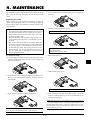
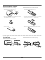
Cleaning
These safety instructions are to ensure the long life of
your projector and to prevent fire and shock. Please read
them carefully and heed all warnings.
1. Unplug the projector before cleaning.
Installation
1. For best results, use your projector in a darkened room.
3. Use a blower or lens paper to clean the lens, and be careful
not to scratch or mar the lens.
2. Place the projector on a flat, level surface in a dry area away
from dust and moisture.
Lamp Replacement
3. Do not place your projector in direct sunlight, near heaters
or heat radiating appliances.
• To replace the lamp, follow all instructions provided on page
E-33.
4. Exposure to direct sunlight, smoke or steam can harm internal components.
• Be sure to replace the lamp when the Status light comes
on. If you continue to use the lamp after 1000 hours of use,
the lamp bulb may shatter, and pieces of glass may be scattered in the lamp case. Do not touch them as the pieces of
glass may cause injury. If this happens, contact your NEC
dealer for lamp replacement.
2. Clean the cabinet periodically with a damp cloth. If heavily
soiled, use a mild detergent. Never use strong detergents
or solvents such as alcohol or thinner.
5. Handle your projector carefully. Dropping or jarring can damage internal components.
6. Do not place heavy objects on top of the projector.
7. If you wish to have the projector installed on the ceiling:
• Allow a minimum of ONE minute to elapse between turning
the lamp off and on.
a. Do not attempt to install the projector yourself.
b. The projector must be installed by qualified technicians
in order to ensure proper operation and reduce the risk
of bodily injury.
High voltage is applied to the lamp immediately when the
power is turned on.
Therefore turning the power off and quickly back on may
shorten the life of your lamp and result in damage to your
projector.
c. In addition, the ceiling must be strong enough to support
the projector and the installation must be in accordance
with any local building codes.
d. Please consult your dealer for more information.
CAUTION
Power Supply
Do not unplug the power cable from the wall outlet under any one of
the following circumstances. Doing so can cause damage to the projector:
1. The projector is designed to operate on a power supply of
100-120 or 200-240 V 50/60 Hz AC. Ensure that your power
supply fits this requirement before attempting to use your
projector.
* While the Hour Glass icon appears.
2. Handle the power cable carefully and avoid excessive bending. A damaged cord can cause electric shock or fire.
* While the message "Please wait a little." appears. This message will be displayed after the projector is turned off.
3. If the projector is not to be used for an extended period of
time, disconnect the plug from the power outlet.
* Immediately after the power cable is plugged into the wall
outlet (the POWER indicator has not changed to a steady
amber glow).
* Immediately after the cooling fan stops working (The cooling fan continues to work for ONE minute after the projector
is turned off with the POWER OFF button).
* While the POWER and the STATUS indicators are alternately
flashing.
E–3
Fire and Shock Precautions
1. Ensure that there is sufficient ventilation and that vents are
unobstructed to prevent the build-up of heat inside your projector. Allow at least 3 inches (10cm) of space between your
projector and a wall.
2. Prevent foreign objects such as paper clips and bits of paper from falling into your projector. Do not attempt to retrieve any objects that might fall into your projector. Do not
insert any metal objects such as a wire or screwdriver into
your projector. If something should fall into your projector,
disconnect it immediately and have the object removed by a
qualified NEC service personnel.
3. Do not place any liquids on top of your projector.
Warnings
• Do not look into the lens while the projector is on. Serious
damage to your eyes could result.
• Keep any items such as magnifying glass out of the light
path of the projector. The light being projected from the lens
is extensive, therefore any kind of abnormal objects that
can redirect light coming out of the lens, can cause unpredictable outcome such as fire or injury to the eyes.
• Do not cover the lens with the supplied lens cap or equivalent while the projector is on. Doing so can lead to melting of
the cap and possibly burning your hands due to the heat
emitted from the light output.
• Do not hold the lens part. Doing so may cause the risk of
injury.
For the optional full function remote control with
the laser pointer
• Do not look into the laser pointer while it is on and do
not point the laser beam at another person. Serious injury could result.
E–4
TABLE OF CONTENTS
Setup ......................................................................... E-23
Orientation ............................................................ E-23
Background ........................................................... E-23
Signal Select ......................................................... E-23
Auto Start .............................................................. E-23
Power Management .............................................. E-23
Power Off Confirmation ......................................... E-23
Mouse Settings ..................................................... E-23
Keystone Save ...................................................... E-23
White Segment ..................................................... E-23
Clear Lamp Hour Meter ........................................ E-23
PC Card Viewer Options ....................................... E-24
Capture Options .................................................... E-24
1. INTRODUCTION
Introduction to the MultiSync LT84/LT140 Projector .... E-6
Getting Started ............................................................ E-6
Getting to Know Your MultiSync LT84/LT140 Projector .... E-7
Front Features ......................................................... E-7
Rear Features ......................................................... E-7
Bottom Features ...................................................... E-7
Top Features ........................................................... E-8
Terminal Panel Features ......................................... E-9
Remote Control Features ...................................... E-10
2. INSTALLATION
Setting Up Your Projector ........................................... E-12
Selecting a Location .................................................. E-12
Using a Tabletop or Cart ............................................ E-12
Distance Chart ........................................................... E-13
Ceiling Installation ..................................................... E-14
Reflecting the Image .................................................. E-14
Wiring Diagram .......................................................... E-15
Tools .......................................................................... E-24
Capture ................................................................. E-24
PC Card Files ........................................................ E-25
ChalkBoard ........................................................... E-25
Help ........................................................................... E-25
Contents ................................................................ E-25
Source Information ................................................ E-25
Projector Information ............................................. E-25
3. OPERATION
General Controls ....................................................... E-17
Using the Menus ........................................................ E-17
Using a USB Mouse .................................................. E-17
Menu Tree .................................................................. E-18
Menu Elements .......................................................... E-19
Menu Descriptions & Functions ................................. E-20
Source Select ............................................................ E-20
RGB ...................................................................... E-20
Video/S-Video ....................................................... E-20
PC Card Viewer ..................................................... E-20
Adjustments ............................................................... E-20
Picture ................................................................... E-20
Volume .................................................................. E-20
Image .................................................................... E-20
Auto Adjust ....................................................... E-21
Position ............................................................. E-21
Pixel Adjust ....................................................... E-21
Resolution ......................................................... E-21
Color Temperature ................................................ E-21
Keystone ............................................................... E-21
Factory Default ...................................................... E-21
Image Options ........................................................... E-21
Image Mode .......................................................... E-21
Aspect Ratio ..................................................... E-21
Video Mode ........................................................... E-22
Gamma ............................................................. E-22
Noise Reduction ............................................... E-22
Color Matrix ...................................................... E-22
Using the PC Card Viewer Function .......................... E-26
Features ................................................................ E-26
Inserting and Ejecting a CompactFlash™ Card .... E-26
Installing the PC Card Viewer
Software ................................................................ E-27
Starting Up the PC Card Viewer Software
on your PC (PC Card Viewer Utility 1.0) ............. E-27
Operating the PC Card Viewer Function
from the Projector (playback) .............................. E-28
Capturing Images Displayed on the Projector ....... E-30
Viewing Digital Images .......................................... E-31
Uninstalling the PC Card Viewer Software ............ E-31
Terminology ........................................................... E-32
4. MAINTENANCE
Replacing the Lamp ................................................... E-33
Remote Control Battery Installation ........................... E-34
Operating Range ....................................................... E-34
5. TROUBLESHOOTING
Status Light Messages .............................................. E-35
Common Problems & Solutions ................................. E-35
When Using the PC Card Viewer Function ................ E-36
6. SPECIFICATIONS
Optical/Electrical/Mechanical..................................... E-37
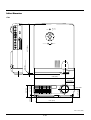
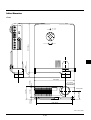
Cabinet Dimensions .................................................. E-38
D-Sub Pin Assignments ............................................. E-40
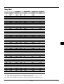
Timing Chart .............................................................. E-41
PC Control Codes ...................................................... E-42
Cable Connection ...................................................... E-43
Projector Options ....................................................... E-22
Menu ..................................................................... E-22
Language .............................................................. E-22
Source Display ...................................................... E-22
Projector Pointer ................................................... E-22
CompactFlash is a trademark of San Disk Corporation.
E–5
1. INTRODUCTION
Introduction to the MultiSync LT84/LT140
Projector
• The supplied card remote control can be used without a cable,
and you can even use the optional full function remote control
and mouse adapter to operate your PC or Macintosh mouse
wirelessly from across the room with the built-in remote mouse
receiver.
• You can control the projector with a PC using the PC Control
port.
• The contemporary cabinet design is light, compact, easy to carry,
and complements any office, boardroom or auditorium.
• Eight kinds of pointers are available for your presentation.
• USB terminal allows USB mouse operation*4.
This section introduces you to your new MultiSync LT84 (SVGA)/
LT140 (XGA) Projector describes the features and controls.
Congratulations On Your Purchase Of The MultiSync LT84/
LT140 Projector
The MultiSync LT84/LT140 is one of the very best projectors available today. The MultiSync LT84/LT140 enables you to project precise images up to 300 inches across (measured diagonally) from your
PC or Macintosh computer (desktop or notebook), VCR, DVD player,
document camera, a laser disc player, or PC Card Viewer.
You can use the projector on a tabletop or cart, you can use the projector to project images from behind the screen, and the projector can
be permanently mounted on a ceiling*1. The remote control can be
used wirelessly.
*1 Do not attempt to mount the projector on a ceiling yourself.
The projector must be installed by qualified technicians in order
to ensure proper operation and reduce the risk of bodily injury.
In addition, the ceiling must be strong enough to support the projector and the installation must be in accordance with any local
building codes. Please consult your dealer for more information.
*2 An XGA image (10242768) is converted into an 8002600 crisp
image with NEC’s Advanced AccuBlend on LT84.
*3 An SXGA image (128021024) is converted into a 10242768
crisp image with NEC’s Advanced AccuBlend on LT140.
*4 The USB terminal meets the USB1.0 specification and accepts a
USB mouse only.
Features you’ll enjoy:
• Simple set up and operation.
• Hot air blown from the vents does not bother the audience during your presentation since the vents are located on the front and
bottom.
• A high-performance AC120 watt P-VIP lamp.
• A wireless card remote control that can be stored in the projector.
• The manual zoom control enables you to adjust the image to be
between 25 and 300 inches (measured diagonally).
• Keystone correction allows you to correct trapezoidal distortion
so that the image is square.
• You can choose between video modes depending on your source:
“normal” for a typical picture, “natural” for true color reproduction.
• The built-in PC Card Viewer allows you to start your presentation even when a PC is not available at the site.
• The “Capture” enables you to capture the current projected image.
• An image can be projected from in front or behind a screen, and
the projector can even be installed on the ceiling.
• NEC’s exclusive Advanced AccuBlend intelligent pixel blending technology - an extremely accurate image compression technology - offers a crisp image with SXGA (128021024) resolution*3 . You can select any point on the screen with the pointer
and enlarge the selected area.
• Supports most IBM VGA, SVGA, XGA*2 , SXGA(with Advanced AccuBlend)*3, Macintosh, component signal (YCbCr /
YPbPr) or any other RGB signals within a horizontal frequency
range of 15 to 85 kHz and a vertical frequency range of 50 to 85
Hz. This includes NTSC, PAL, PAL60, SECAM and NTSC4.43
standard video signals.
Getting Started
The fastest way to get started is to take your time and do everything
right the first time. Take a few minutes now to click through the CDROM and review the user’s manual. This may save you time later on.
At the beginning of each section of the manual you’ll find an overview. If the section doesn’t apply, you can skip it.
NOTE: Composite video standards are as follows:
NTSC: U.S. TV standard for video in U.S. and Canada.
PAL: TV standard used in Western Europe.
PAL60: TV standard used for NTSC playback on PAL TVs.
SECAM: TV standard used in France and Eastern Europe.
NTSC4.43: TV standard used in Middle East countries.
E–6
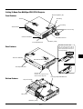
Getting To Know Your MultiSync LT84/LT140 Projector
Monaural Speaker (1W)
Front Features
Controls
Zoom Ring
P
O
S
W
E
R
TA
TU
S
O
E NTE R
N
/O
FF
CA
S
E
LE
C
T
NCEL
S
O
U
R
Focus Ring
C
E
M
EN
U
A
U
TO
A
D
JU
S
T
Terminal Panel
Lens and Lens Cap
One-Push Tilt Button
Front Remote Sensor
Ventilation (outlet)
Front Adjustable Foot
Card Remote Control Slot
The card remote control can be
stored in the cabinet. To insert or
pull out the card remote control, follow the procedures:
Rear Features
EN
U
FF
CA
S
E
LE
C
T
NCEL
S
O
U
R
One-Push Tilt Button
M
C
E
A
U
TO
A
D
JU
S
T
Push to insert
P
O
W
E
S
R
TA
TU
S
O
N
/O
E NTE R
Rear Remote Sensor
Press down to release
Front Adjustable Foot
AC Input
Connect the supplied power
cable’s three-pin plug here.
Bottom Features
Lamp Cover Screw
Lamp Cover
Ventilation (outlet)
E–7
Lever-Type Adjustable Rear Foot
Top Features
1
2
SOURCE
AUTO ADJUST
3
MENU
4
SELECT
6
E
NT
L
5
ER
CA
NC
E
9
7
STATUS
ON/OFF
POWER
8
1 Source Button
Use this button to select a video source such as a PC, VCR, DVD
player or PC Card Viewer (CompactFlash card installed).
7 Status Indicator
When this is lit red continually, it’s warning you that the projection
lamp has exceeded 1000 hours of service. After this light appears,
it is advisable to replace the projection lamp as soon as possible.(See
page E-33)
In addition the message “LAMP USAGE XX HOURS” appears
continually when the on-screen menu is not displayed. If this light
blinks red rapidly, it indicates that the lamp cover is not attached
properly or the projector is overheated. See the Status Light Messages on page E-35 for more details.
2 Auto Adjust Button
Use this button to adjust Position-H/V and Pixel Clock/Phase for
an optimal picture. Some signals may not be displayed correctly or
take time to switch to another.
3 Menu Button
Displays the main menu for operation.
4 Select (▲▼§ ©) / (+) (–) Buttons
▲▼: Use these buttons to select the menu of the item you wish
to adjust.
§ ©: Use these buttons to change the level of a selected menu
item.
A press of the © button executes the selection. When no menus
appear, these ▲▼ buttons work as a volume control.
When the pointer is displayed, these § © ▲▼ buttons move the
pointer.
8 Power Indicator
When this indicator is green, the projector is on; when the indicator is amber, it is in standby mode.
9 Power Button
Use this button to turn the power on and off when the power is
supplied and the projector is in standby mode.
NOTE: To turn off the projector, press and hold this button for a
minimum of two seconds.
5 Enter Button
Executes your menu selection and activates items selected from
the menu.
6 Cancel Button
Press this button to exit “Menus”. Press this button to return the
adjustments to the last condition while you are in the adjustment
or setting menu.
E–8
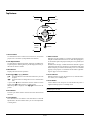
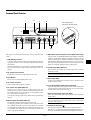
Terminal Panel Features
2
1
3
4
Slot for Kensington
MicroSaver Security System
PC CARD
ACCESS
O
N
/O
FF
CA
NC EL
USB
RGB INPUT
S-VIDEO
VIDEO
AUDIO
E
R
PC CONTROL MOUSE OUT
L (MONO)
5
6
7
8
9
10
R
11
7 RGB Input/ Component Input Connector (Mini D-Sub 15 pin)
Connect your PC or other RGB equipment such as IBM or compatible
computers. Use the signal cable that’s supplied to connect to a PC. Or
connect a Macintosh or compatible computer here using the signal
cable and the pin adapter that is supplied. This also serves as a component input connector which allows you to connect a component video
output of a component equipment such as a DVD player.
This panel is located on the left side and is where you connect your
cables.
1 USB (Mouse) Terminal
Connect a commercially available mouse that supports USB. You
can operate the menu or PC Card Viewer with the USB mouse via
this terminal.
Note that this terminal is not used with a computer and that there
may be some brands of USB mouse that the projector does not
support.
8 S-Video Input (Mini DIN 4 Pin)
Here is where you connect the S-Video input from an external
source like a VCR.
2 PC Card Access Indicator
Lights while accessing a CompactFlash memory card.
NOTE: S-Video provides more vivid color and higher resolution
than the traditional composite video format.
3 Eject Button
Press to eject a CompactFlash memory card.
9 Video Input (RCA)
Connect a VCR, DVD player, laser disc player, or document camera here to project video.
4 PC Card Access Slot
Insert a CompactFlash memory card here.
10 Left Channel/Mono Audio Input Jack (RCA)
This is the left channel audio input for stereo sound coming from
video equipment or audio system. This also serves as your monaural audio input. (Video and S-video only)
5 PC Control Port (Mini DIN 8 Pin)
Use this port to connect your PC to control your projector. This
enables you to use your PC and serial communication protocol to
control the projector. If you are writing your own program, typical
PC control codes are on page E-42.
A cap is put on the port at the factory. Remove the cap when using
the port.
Right Channel Audio Input Jack (RCA)
This is the right channel audio input for stereo sound. (Video and
S-video only)
NOTE: Although stereo Audio input jacks are provided, the projector will only produce Mono sound. This is due to one speaker
limitation of the projector.
6 Mouse Output Port (Mini DIN 8 Pin)
Not available when the supplied card remote is used.
Use this port to operate your computer’s mouse functions from the
NEC optional full function remote control. When your computer
is connected here with the NEC optional full function remote control (LT40RT), the remote sensors on the projector cabinet will
receive your mouse commands.
11 Built-in Security Slot ( )
This security slot supports the MicroSaver® Security System.
MicroSaver® is a registered trademark of Kensington Microware Inc.
The logo is trademarked and owned by Kensington Microware Inc.
E–9
Remote Control Features
17
11
16
Full Function Remote Control
LT40RT (optional)
POWER
OFF
ON
12
COMPUTER
Wireless Card Remote Control
(supplied)
ME
25
S JAPAN H
A
3
MENU
LASER
13
14
18
+
CANCEL
R-CLICK
HELP POINTER PIC-MUTE
CE
L
?
9
N
MAGNIFY
+
POINTER
PIC.
MUTE
-
MAGNIFY
7
10
LT
20
S
4
5
8
CA
O
R
T
ER
2- L iC E L L 3 V
C
1
2
-
SELECT
EN
M nO
AUTO ADJ.
NU
6
NOTE: For the supplied card remote control, remove the transparent insulation tape by pulling it
before use. See page E-34 for battery installation.
PROJECTOR
SOURCE
AUTO
ADJ.
SOURCE
PJ
HELP
RD-361E
Remote Jack
Not available on LT84/LT140
Wireless Card Remote Control
1 Source Button
Press to select a video source.
2 Auto Adjust Button
Use this button to adjust Position-H/V and Pixel Clock/Phase for
an optimal picture. Some signals may not be displayed correctly,
or in some cases it may take some time for a source to be switched
to another.
4 Select (▲▼§ ©) / Mouse / (+) (–) Buttons
▲▼: Use these buttons to select the menu of the item you wish
to adjust.
§ ©: Use these buttons to change the level of a selected menu
item.
A press of the © button executes the selection. When no menus
appear, these ▲▼ buttons work as a volume control.
When the pointer is displayed, these § © ▲▼ buttons move the
pointer. The Mouse button is available on the full function remote
control only.
NOTE: The Mouse Output port is not available on the card remote control because mouse codes are not output.
3 Menu Button
Displays the main menu for operation.
5 Cancel/ Right Click Button
Press this button to exit “Menus”. Press this button to return the
adjustments to the last condition while you are in the adjustment
or setting menu. The Right-Click button is available on the full
E–10
function remote control only.
6 Enter Button
Executes your menu selection and activates items selected from
the menu.
17
7 Magnify Button
Use the (+) or (–) button to adjust the image size up to 400%.
When the Pointer is displayed, the magnified image is displayed at
the center of the Pointer. When the Pointer is not displayed, the
magnified image is displayed at the center of the screen.
16
8 Pointer Button
Press this button to display one of the eight pointers; press again to
hide the pointer.
15
9 Picture Mute Button
This button turns off the image and sound for a short period of
time. Press again to restore the image and sound.
15 Left Click Button
Use this button to enter your menu selection. It works the same as
the “Enter” button on the cabinet or the card remote control.
10 Help Button
Provides information about operation and adjustment procedures
or the set information for the current menu or adjustment during
menu operation. This also displays information how to use the Help.
16 Laser Pointer
Beams a laser light when “Laser” button is pressed.
Wireless Full Function Remote Control (Optional)
You can use your optional full function remote control wireless to
operate your projector.
With the mouse output port connected to your computer, you can
also use the projector’s remote control to operate your computer’s
mouse wireless. (See page E-16 to connect your computer to the mouse
output port.)
NOTE: If you are using a Macintosh computer, you can click either
the right or left button to activate the mouse.
17 Infrared Transmitter
Direct the remote control toward the remote sensor on the projector cabinet.
18 Mouse Pad(▲▼§ ©)
Works as a mouse for your projected computer image. This pad is
also used to adjust position.
This pad selects the submenu you want to adjust.
After you make your on-screen menu selection, use this pad to
adjust the level up or down.
Remote Control Precautions
•
•
•
•
Handle the remote control carefully.
If the remote control gets wet, wipe it dry immediately.
Avoid excessive heat and humidity.
If you will not be using the remote control for a long time, remove the batteries.
• Do not place the batteries upside down.
11 Power On And Off
If power is applied, you can use this button to turn your projector
on and off.
NOTE: To turn off the projector, press and hold the POWER OFF
button for a minimum of two seconds.
NOTE: Before you use the card remote control for the first time, be
sure to remove the insulation tape from the card remote control.
12 LED
Flashes when any button is pressed.
* Keep the coin cell battery out of reach of children so as not to
allow them to swallow the cell battery.
13 Computer/Projector Select
Use this button to switch between “Computer” and “Projector”.
When “Computer” is selected, the remote control works as your
computer mouse. In this mode only Mouse pad, Laser, R-Click
and L-Click buttons are available.
Also observe the following when using the optional
full function remote:
NOTE: When either the Menu, Help or Pointer button is pressed,
the Computer/Projector Select button lights in red to indicate that
your projector is in the Projector mode. If no buttons are pressed
within 10 seconds, the light goes out and the Projector mode is
canceled.
14 Laser Button
Press and hold this button to activate the laser pointer. When lit,
you can use the laser to draw your audience’s attention to a red dot
that you can place on any object within 30 feet (10 m).
• Do not look into the laser pointer while it is on.
• Do not point the laser beam at a person.
NOTE:
The optional full function remote control package (LT40RT) includes:
1) Full function remote control
2) Mouse adapter for Macintosh
3) Mouse adapter for IBM PS/2
4) Serial cable
5) Two batteries (AA)
6) Remote control case
E–11
The LT40RT optional remote control mouse kit can be obtained
from your dealer at additional cost.
2. INSTALLATION
This section describes how to set up your MultiSync LT84/LT140
projector and how to connect video and audio sources.
Setting up Your Projector
Your MultiSync LT84/LT140 Projector is simple to set up and use.
But before you get started, you must first:
1. Determine the image size.
2. Set up a screen or select a non-glossy white wall onto which you
can project your image.
2. Connect the power cable, remove the lens cap and turn the projector on. (If no input signal is available, the projector will display a
background image.)
3. Ensure that the projector is square to the screen.
4. Move the projector left or right to center the image horizontally
on the screen.
Top view
Screen
Carrying The Projector: Always carry your projector in the supplied
soft carrying case.
You must put the projector in the soft carrying case with
the lens upward as shown below. This is to prevent the
lens from damage.
Upward
5. To center the image vertically, lift the front edge of the projector
and press the One-Push Tilt buttons on the front side of the projector, just above the feet, to release the Front Adjustable feet.
(There is approximately 5 degrees of up and down adjustment for
the front of the projector.)
E
C
EN
U
Side view
FF
S
CAN
E
LE
C
T
CE L
S
O
U
R
M
A
U
TO
Band
Screen
P
O
W
E
S
R
TA
TU
S
O
N
/O
E NTE R
Bottom
Carrying Case
NOTE: Do not put a notebook computer in the soft carrying case.
Doing so can cause damage to the computer. When moving the projector or when it is not in use, cover the lens cap.
US
AT
ER
ST
W
PO
ON
M
CE
UR
SO
CT
LE
SE
CANC
EL
E NTE R
E
E
M
CE
UR
SO
CT
LE
SE
CANC
EL
NU
FF
FF
/O
/O
ON
E NTE R
US
AT
ST
W
ER
TO
AU
NU
TO
AU
Lens cap
String
M
CE
EN
U
CAN
CE L
FF
SE
CT
SO
AU
The further your projector is from the screen or wall, the larger the
image. The minimum size the image can be is approximately 25"
(0.6 m) measured diagonally when the projector is roughly 4 feet
(1.2 m) from the wall or screen. The largest the image can be is 300"
(7.6 m) when the projector is about 40 feet (12.2 m) from the wall or
screen.
UR
/O
ON
US
PO
ST
AT
E NTE R
W
ER
Selecting a Location
TO
6. If necessary, adjust the front or rear feet to properly position the
projected image on the screen.
If the projected image does not appear square to the screen then
use keystone correction for proper adjustment. The Lever-Type
Adjustable Rear foot height can be changed up to 3 degrees.
LE
Rivet
PO
Attaching the lens cap to
the lens hood with the supplied string and rivet.
Using a Tabletop or Cart
1. Place your projector on a flat level surface at the optimal distance
from the screen or wall so you realize the size image you want.
(Avoid having bright room lighting or sun light directly on the
screen or wall where you’ll be projecting the image.)
7. Adjust the size of the image using the Zoom ring on the lens.
E–12
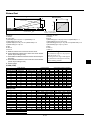
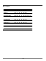
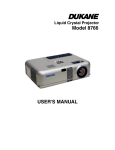
Distance Chart
Screen
C
Screen (inch)
H
Screen center
E
A
D
α
EV
D
B
Projector base
LT84: 1.87”(47.6mm)
LT140: 1.98”(50.4mm)
Screen bottom
Unit (inch)
A=C/cosα
B=3.7H / 25.4
C(XGA:tele)=(2.41 x H)-2.0 or C(XGA:wide) x 1.2
C(XGA:wide)=(2.0 x H)-2.0
C(SVGA:tele)=(2.43 x H)-1.75 or C(SVGA:wide) x 1.2
C(SVGA:wide)=(2.0 x H)-1.9
D=E/2
E=H/4 x 3
a=H/4 x 5
Unit (mm), H= inch
A=C/cosα
B=3.7H
C(XGA:tele)={(2.41 x H)-2.0} x 25.4 or C(XGA:wide) x 1.2
C(XGA:wide)={(2.0 x H)-2.0} x 25.4
C(SVGA:tele)={(2.43 x H)-1.75} x 25.4 or C(SVGA:wide) x 1.2
C(SVGA:wide)={(2.0 x H)-1.9} x 25.4
D=E/2
E=H/4 x 3
a=H/4 x 5
A: Distance between lens center and screen center
B: Vertical distance between lens center and screen bottom
(screen top for ceiling mount)
C: Horizontal throw distance between screen surface and projector lens
D: Vertical distance between screen center and screen bottom
(screen top for ceiling mount)
E: Screen Height
Installation Angle
The installation angle for the projector
must not exceed +/-15˚.
Deviating from this angle could degrade
the performance of the projector and may
cause reliability problems.
S-VGA (LT84)
a
Screen size (Diagonal)
25
40
60
80
100
120
150
200
240
300
Screen Size (inch)
H
Screen Width
20
32
48
64
80
96
120
160
192
240
E
Height of screen
15
24
36
48
60
72
90
120
144
180
Projection Distance
V. Distance between Lens Center and Screen Bottom
C(mm) C(inch) C(mm) C(inch) B(mm) B(inch) B(mm) B(inch)
WIDE
TELE
WIDE
TELE
–
–
1190
46.9
–
–
74
2.9
1600
63.0
1930
76.0
117
4.6
117
4.6
2420
95.3
2910
114.6
176
6.9
176
6.9
3240
127.6
3900
153.5
235
9.3
235
9.3
4060
159.8
4890
192.5
294
11.6
294
11.6
4880
192.1
5870
231.1
352
13.9
352
13.9
6110
240.6
7350
289.4
440
17.3
440
17.3
8170
321.7
9820
386.6
587
23.1
587
23.1
9820
386.6 11790 464.2
705
27.8
705
27.8
12280
483.5
–
–
881
34.7
881
34.7
Screen Size (inch)
H
Screen Width
20
32
48
64
80
96
120
160
192
240
E
Height of screen
15
24
36
48
60
72
90
120
144
180
Projection Distance
V. Distance between Lens Center and Screen Bottom
C(mm) C(inch) C(mm) C(inch) B(mm) B(inch) B(mm) B(inch)
WIDE
TELE
WIDE
TELE
–
–
1170
46.1
–
–
74
2.9
1580
62.2
1910
75.2
119
4.7
119
4.7
2400
94.5
2890
113.8
178
7.0
178
7.0
3220
126.8
3870
152.4
237
9.3
237
9.3
4030
158.7
4850
190.9
297
11.7
297
11.7
4850
190.9
5830
229.5
356
14.0
356
14.0
6080
239.4
7300
287.4
445
17.5
445
17.5
8120
319.7
9750
383.9
593
23.3
593
23.3
9750
383.9 11710 461.0
712
28.0
712
28.0
12200
480.3
–
–
890
35.0
890
35.0
XGA (LT140)
a
Screen size (Diagonal)
25
40
60
80
100
120
150
200
240
300
NOTE: Distances may vary +/–5%.
E–13
Ceiling Installation
C
Projector base
LT84: 1.87”(47.6mm)
LT140: 1.98”(50.4mm)
α
B
Screen top
A
D
E
Screen center
WARNING
• Installing your projector on the ceiling must be done by a qualified technician. Contact your NEC dealer for more information.
* Do not attempt to install the projector yourself.
• Only use your projector on a solid, level surface. If the projector falls to the ground, you can be injured and the projector
severely damaged.
• Do not use the projector where temperatures vary greatly. The
projector must be used at temperatures between 41˚F (5˚C)
and 95˚F (35˚C).
• Do not expose the projector to moisture, dust, or smoke. This
will harm the screen image.
• Ensure that you have adequate ventilation around your projector so heat can dissipate. Do not cover the vents on the side
or the front of the projector.
If your projector is mounted on the ceiling and your image is upside
down, use the “Menu” and “Select” buttons on your projector cabinet or ▲▼ button on your remote control to correct the orientation.
(See page E-23.)
Reflecting the Image
Using a mirror to reflect your projector’s image enables you to enjoy
a much larger image. Contact your NEC dealer if you need a mirror.
If you’re using a mirror and your image is inverted, use the “Menu”
and “Select” buttons on your projector cabinet or ▲▼ buttons on
your remote control to correct the orientation. (See page E-23.)
E–14
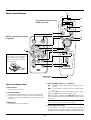
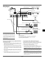
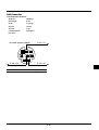
Wiring Diagram
To video, S-video, and audio VCR, DVD Player or LaserDisc Player
inputs on the projector.
Commercially available
USB Mouse
USB
PC CONTROL MOUSE OUT
Optional Component V cable
DVD Player (with component output)
PC CARD
ACCESS
RGB INPUT
VIDEO
S-VIDEO
AUDIO
Document Camera
L (MONO)
R
Optional serial cable
Optional mouse adapter (For Macintosh)
Macintosh or Compatibles
(Desk top type or notebook type)
Pin adapter for Macintosh (supplied)
Optional mouse adapter (For IBM PS/2)
NOTE: When using with a notebook PC, be
sure to connect between the projector and
the notebook PC before turning on the power
to the notebook PC. In most cases signal
cannot be output from RGB output unless the
notebook PC is turned on after connecting
with the projector.
IBM PC or Compatibles
(Desk top type or notebook type)
Signal cable (supplied)
To mini D-Sub 15-pin connector on the projector. It is recommended that
you use a commercially available distribution amplifier if connecting a
signal cable longer than the supplied one.
Remote Control Guideline for the Optional Full Function Remote Control
1. Plug the optional serial cable with the mouse output port of the
projector into your computer’s mouse port and restart your computer to gain remote mouse control.
2. When using the remote control’s built-in infrared mouse on a laptop
computer, the laptop’s mouse, trackball or trackpad will be disabled. Disconnect the optional serial cable from the mouse output
port and restart your computer to regain trackball or trackpad
mouse control.
3. If the screen goes blank while using your remote control, it may
be the result of the computer’s screen-saver or power management software.
4. If you accidentally hit the OFF button on the remote control, wait
one full minute and then press the ON button to resume.
Connecting Your PC or Macintosh Computer
Connecting your PC or Macintosh computer to your MultiSync LT84
(SVGA)/LT140 (XGA) projector will enable you to project your
computer’s screen image for an impressive presentation.
To connect to a PC or Macintosh, simply:
1. Turn off the power to your projector and computer.
2. Use the signal cable that’s supplied to connect your PC or
Macintosh computer to the projector. For older Macintosh, use
the supplied pin adapter to connect to your Mac's video port.
NOTE:The new Macintosh computer such as G3 will have the 15
pin HD connector. The LT84/LT140's "Plug and Play" data will
be downloaded to the Macintosh. Therefore, the Mac adapter will
not be necessary.
3. Turn on the projector and the computer.
4. If the projector goes blank after a period of inactivity, it may be
caused by a screen saver installed on the computer you’ve connected to the projector.
E–15
When using a Macintosh with the projector, set the DIP switches of
the supplied pin adapter according to your resolution. After setting,
restart your Macintosh.
See the following pages for setting of the DIP switches.
• When using with a Macintosh, SVGA(8002600)/
XGA(10242768) is recommended if your Macintosh supports
this mode.
• When using with a Macintosh PowerBook, output may not be
set to 8002600 unless “mirroring” is off on your PowerBook.
Refer to owner’s manual supplied with your Macintosh computer for mirroring.
NOTE: A Video Adapter cable manufactured by Apple Computer is
needed for a PowerBook which does not have a mini D-Sub 15-pin
connector.
Settings for Monitor Mode
Number of DIP switch
Resolution
13" multi-scan mode /16"-13"
17" multi-scan mode /19"-13"
21” multi-scan mode /21"-13"
13" fixed mode /640x480
VGA/SVGA mode
16" fixed mode /832x624
19" fixed mode /1024x768
21" fixed mode /1152x870
1
2
ON
ON
ON
ON
ON
ON
ON
ON
3
4
ON
ON
ON
ON
6
ON
ON
ON
(only when using the optional full function remote control)
ON
NOTE: For settings other than display modes supported by your
Macintosh and the projector, use of the DIP switch may bounce an
image slightly or may display nothing. If this happens, set the DIP
switch to the 13" fixed mode and then restart your Macintosh. After
that, restore to a displayable mode and then restart the Macintosh
again. Make sure that the projector and your Macintosh are connected with the pin adapter and the supplied signal cable (mini DSub 15-pin connector) and then restart your Macintosh.
Examples of DIP switch setting
17" multi-scan mode
ON
VGA/SVGA mode
19" fixed mode
ON
1
2
3 4
5
6
ON
1
2
3 4
5
6
1
2
3 4
5
Use common RCA cables (not provided) to connect your VCR or
laser disc player to your projector. To make these connections, simply:
1. Turn off the power to the projector and VCR or laser disc player.
2. Connect one end of your RCA cable to the video output connector
on the back of your VCR or laser disc player, connect the other
end to the Video input on your projector. Use standard RCA audio
patch cords to connect the audio from your VCR or laser disc
player to the projector (if your VCR or laser disc player has this
capability). Be careful to keep your right and left channel connections correct for stereo sound.
3. Turn on the projector and the VCR or laser disc player.
Connecting Your Computer to the Mouse Output Port
ON
ON
ON
ON
Connecting Your VCR or Laser Disc Player
NOTE: Refer to your VCR or laser disc player owner’s manual for
more information about your equipment’s video output requirements.
5
ON
ON
3. Turn on the projector and the DVD player.
NOTE: Refer to your DVD player’s owner’s manual for more information about your DVD player’s video output requirements.
NOTE: To use the Mouse Output port, you need the optional serial
cable, the optional mouse adapter(for IBM PS/2 or Macintosh), and
the optional full function remote control.
The built-in remote mouse receiver enables you to operate your
computer’s mouse functions from the optional full function remote
control. It is a great convenience for clicking through your computergenerated presentations.
To connect the mouse output port:
1. Turn off your computer.
2. For PCs: Remove your current mouse and connect the optional
serial cable from the mouse output to your PC’s mouse port. (Use
the 6-pin adapter for connecting to a PS/2 computer.)
For Macintosh: Remove your current mouse from your computer,
attach the Macintosh adapter to the mouse output port’s serial cable,
and connect the projector to your mouse port.
3. When the built-in remote mouse receiver is available, it will disable your regular mouse, disconnect the serial cable and restart
your computer.
6
USB
PC CONTROL MOUSE OUT
NOTE: Refer to your computer’s owner’s manual for more information about your computer’s video output requirements and any special identification or configuring your projector’s image and monitor may require.
S-VIDEO
VIDEO
AUDIO
L (MONO)
R
IBM PC/AT
Serial cable (included
with the optional full
function remote control)
Connecting Your DVD Player
You can connect your projector to a DVD player with component
outputs or Video output. To do so, simply:
1. Turn off the power to your projector and DVD player.
2. If your DVD player has the component video (Y,Cb,Cr) output,
use the optional 15-pin-to-RCA x 3 cable to connect your DVD
player to the RGB INPUT connector on the projector.
For a DVD player without component video (Y,Cb,Cr) outputs,
use common RCA cables (not provided) to connect a composite
VIDEO output of the DVD player to the Video Input of the projector.
PC CARD
ACCESS
RGB INPUT
USB
PC CONTROL MOUSE OUT
PC CARD
ACCESS
RGB INPUT
S-VIDEO
VIDEO
Macintosh
AUDIO
L (MONO)
R
IBM PS2
Serial cable (included
with the optional full
function remote control)
NOTE:Some computers or software programs may not work with the
MOUSE OUT port.
E–16
3.OPERATION
This section describes how to select a computer or video source, how
to adjust the picture, and how to customize the menu or projector
settings.
General Controls
Before you turn on your projector, ensure that the computer or video
source is turned on and that your lens cap is removed.
1. Turn on the Projector
Plug the supplied power cable in the wall outlet. The projector
will go into its standby mode and the power indicator will glow
amber.
Only after you press the “On” button on the projector cabinet or
the optional full function remote control will the power indicator
turn to green and the projector become ready to use.
NOTE: To turn the projector on by plugging in the power cable,
use the menu and enable the “Auto Start” feature. (See page 23.)
2. Select the Computer, Video Source or PC Card Viewer
Press the Source button on the remote control or the projector
cabinet to select “Video” (VCR, document camera, or laser disc
player), S-Video”, “RGB” (computer or DVD with component
output) or “PC Card Viewer” (CompactFlash Card) to display the
image.
Or press the “Menu” button on the remote control or the cabinet
and use the menu to select your video source: “Video”, “S-Video”,
“RGB”, or “PC Card Viewer”.
NOTE:The standard video signal NTSC4.43 and PAL60 must be
manually selected from the pull-down menu for Video System on
Setup because it cannot be automatically detected.
3. Adjust the Image Size and the Focus
Use the Zoom ring to adjust the image size, then use the Focus
ring knob to obtain the best focus.
Use the “Magnify” button (+) or (-) on the remote control to make
the image larger up to 400%.
4. Turning off the Projector
First press and hold the POWER button on the cabinet or the “OFF”
button on the remote control for a minimum of two seconds.
The power indicator will glow amber. Then, unplug the power
cable. The power indicator will go out.
NOTE: When using a USB mouse, click the mouse button to display the main menu. For other operations, do the same way as
you use your PC mouse.
2. Press the ▲▼ buttons on the card remote control, the mouse pad
on the full function remote control or the projector cabinet to highlight the menu for the item you want to adjust or set.
3. Press the © button or the “Enter” button on the projector cabinet
or the card remote control or the “Left Click” button on the optional full function remote control to select a submenu or item.
4. Adjust the level or turn the selected item on or off by using “Select” § or © buttons on the cabinet, the card remote control or
the “Mouse pad” on the optional full function remote control. The
on-screen slide bar will show you the amount of increase or decrease.
5. The change is stored until you adjust it again.
ENTER:
CANCEL: Return to the previous screen without storing settings
or adjustments.
6. Repeat steps 2-5 to adjust an additional item, or press “Cancel”
on the projector cabinet or the remote control to quit the menu
display.
Using a USB Mouse
Using a USB mouse gives you a smooth operation. A commercially
available USB mouse is required.
NOTE:There may be some brands of USB mouse that the projector
does not support.
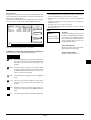
Operate the Menus using the USB mouse
Mouse Cursor
When connecting a USB mouse to the projector, you get a mouse
cursor on the screen.
Unless you use your USB mouse within 10 seconds, the mouse
cursor disappears.
Menu Display
Clicking with a mouse button displays the main menu.
Clicking displays the pull-down menu.
To close the menu, click anywhere in the background.
IMPORTANT:
• The projector should be unplugged if it will not to be used for an
extended period.
• To turn off the image and sound briefly (five minutes or less),
use the “Picture Mute” button instead of turning the projector
off and on.
• The projector will display a black, blue image or logo if no input
signal is present.
• Do not turn the projector off and then immediately back on. The
projector needs to cool for a minute before it can be restarted.
Stores the setting or adjustments.
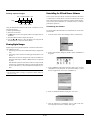
Adjusting and Setting Display
You can select a menu item and click with a mouse button to
make adjustments and setting.
Examples
Using the Menus
NOTE: The on-screen menu may not be displayed correctly while
interlaced motion video image is projected.
1. Press the “Menu” button on the remote control or projector cabinet to display the Main Menu.
E–17
Click (or press and hold) the mouse button § or © to adjust the
brightness.
Or click and drag the mouse button on the slide bar horizontally
to adjust it.
To save the adjustments, click . The display is closed.
If you click anywhere in the background while displaying adjustment and setting menu or dialog box, you will get the main menu
at the clicking point.
Menu Tree
Main Menu
Sub Menu
Main Menu
Source Select
Source Select
RGB
Adjustments
Video
Image Options
S-Video
Projector Options
PC Card Viewer
Items
Adjustable Sources
Brightness
Contrast
Color
Hue
Sharpness
R, V, C
R, V, C
V, C
V, C
V
Auto Adjust
Position
Pixel Adjust
Resolution
R
R
R
R, V, C
Tools
Help
Adjustments
Picture
V, C
Volume
Image
Color Temperature
All
Keystone
All
All Data/Current Signal
Factory Default
Aspect Ratio
V, C
Video Mode
Gamma
Noise Reduction
Color Matrix
R, V, C
V, C
C
Projector Options
Menu
Language
Source Display
Projector Pointer
Image Options
Image Mode
Setup
Tools
Capture
PC Card Files
ChalkBoard
Help
Contents
Source Information
Projector Information
NOTE:
Adjustable sources R=RGB
V=Video/S-Video
C=Component
All=All sources (including PC Card Viewer)
Orientation
Background
Signal Select
Auto Start
Power Management
Power Off Confirmation
Mouse Button
Mouse Sensitivity
Clear Lamp Hour Meter
Keystone Save
White Segment
PC Card Viewer Options
Capture Options
Source Name
Input Terminal
Horizontal Frequency
Vertical Frequency
Sync Polarity
Signal Type
Video Type
Sync Type
Interlace
Resolution
Aspect Ratio
Gamma
Noise Reduction
Color Matrix
Matrix Type
Lamp Hour Meter
E–18
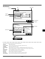
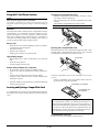
Menu Elements:
Tab
Title bar
Close button
Setup
Page1 Page2 Page3
Signal Select
Orientation
Highlight
Front Floor
Solid triangle
Background
RGB
Auto
VIDEO
Auto
S-VIDEO Auto
Blue
OK
Cancel
Cancel Button
OK Button
Setup
Page1 Page2 Page3
Check box
Mouse
Button
Right Hand
Radio button
Auto Start
Left Hand
Sensitivity
Fast
Medium
Slow
Power Management
Power Off Confirmation
Keystone Save
Clear Lamp Hour Mater
White Segment
OK
Cancel
Slide bar
Brightness
○ ○ ○ ○ ○ ○ ○ ○ ○ ○ ○ ○ ○ ○ ○ ○ ○ ○ ○ ○ ○ ○ ○ ○ ○ ○ ○ ○ ○ ○ ○ ○ ○ ○ ○ ○ ○ ○ ○ ○ ○ ○ ○ ○ ○ ○ ○ ○ ○ ○ ○ ○ ○ ○ ○ ○ ○ ○ ○ ○ ○ ○ ○ ○
Menu windows or dialog box typically have the following elements:
Title bar:
Indicates the menu title.
X Close button: Click to close the window with saving changes. (USB mouse only)
Highlight:
Indicates the selected menu or item.
Solid triangle:
Indicates further choices are available. A highlighted triangle indicates the item is active.
Tab:
Indicates a group of features in a dialog box. Clicking on any tab brings its page to the front.
Radio button:
Use this round button to select an option in a dialog box.
Check box:
Place a checkmark in the square box to turn the option On.
Slide bar:
Indicates settings or the direction of adjustment.
OK button:
Press to confirm your setting. You will return to the previous menu.
Cancel button:
Press to cancel your setting. You will return to the previous menu.
E–19
Menu Descriptions & Functions
Source Select
Enables you to select a video source such
as a VCR, DVD player, laser disc player,
computer or document camera depending on what is connected to your inputs.
Press the “Select” button on the projector cabinet or ▲▼ buttons on your remote control to highlight the menu for
the item you want to adjust.
Source Select
RGB
Video
S-Video
PC Card Viewer
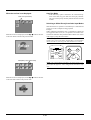
Jump:
Displays a list of slides while you are playing back.
Select:
Displays a list of folders while you are playing back.
Delete: Deletes a captured slide(s) or all the captured slides
in the selected folder.
View:
Hides the tool bar while you are playing back. Clicking with the right button of a mouse shows it again.
Adjustments
Provides access to controls for your image and sound. Use the ▲▼ buttons on
your remote control to highlight the menu
for the item you want to adjust.
Adjustments
Picture
RGB
Selects the computer connected to your RGB or component signal.
Volume
NOTE: An optional component cable (Component V cable) is needed
for a component signal.
Image
Color Temperature
Video
Keystone
Selects what is connected to your Video input-VCR, laser disc player,
DVD player or document camera.
Factory Default
S-Video
Selects what is connected to your S-Video input-VCR, DVD player,
or laser disc player.
Brightness
NOTE: A frame may freeze for a brief period of time when a video is
played back in fast-forward or fast-rewind with a Video or S-Video
source.
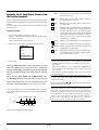
Picture (not available for PC Card Viewer)
PC Card Viewer
Brightness:
Adjusts the brightness level or the back raster intensity.
Contrast:
Adjusts the intensity of the image according to the
incoming signal.
Color:
Increases or decreases the color saturation level (not
valid for RGB).
Hue:
Varies the color level from +/- green to +/-blue. The
red level is used as reference. This adjustment is only
valid for Video and Component inputs (Not RGB).
Sharpness:
Controls the detail of the image for Video (Not for
RGB and Component).
This feature enables you to make presentations using a CompactFlash
card that contains captured images and slides created with the exclusive PC Card Viewer Utility contained in the CD-ROM. See page E27 for installing the PC Card Viewer Utility. The starting screen for
the PC Card Viewer varies depending on the settings of the Setup's
Page 3. See Setup on page E-24.
NOTE: Even if you switch the current PC Card Viewer source to
another source, the current slide is retained. When you return back to
the PC Card Viewer, you will get the slide that has been retained.
A launcher will appear when you press the MENU button.
Prev Play/Stop Select View
Volume (not available for PC Card Viewer and RGB)
Adjusts the sound level of the projector.
Drag
Next
Image (not available for PC Card Viewer)
Jump Delete
Image
Auto Adjust
The launcher is a tool bar including the following buttons:
Drag:
Drags to move the tool bar. (for USB mouse operation only)
Prev:
Returns to the previous slide or folder.
Next:
Advances to the next slide or folder.
Position
Pixel Adjust
Resolution
Play/Stop: Plays back automatically or manually depending
on the setting on PC Card Viewer Options of the menu.
This allows you to stop Auto Play while you are playing back and to resume playing from the selected slide
or folder when “Auto Play” is selected. This allows
you to move on to the next slide when “Manual Play”
is selected.
E–20
Allows for adjustments of the image position and stability.
Auto Adjust:
When “Auto Adjust” is set to “On”, the projector automatically
determines the best resolution for the current RGB input signal
to project an image using NEC’s Advanced AccuBlend Intelligent Pixel Blending Technology.
The image can be automatically adjusted for position and stability; “Horizontal Position”, “Vertical Position” and “Pixel Adjust.”
On:
Automatically adjusts image “Horizontal Position”, “Vertical Position” and “Pixel Adjust.”
Off:
User can adjust the image display functions (“Horizontal
Position”, “Vertical Position” and “Pixel Adjust”) manually.
Keystone
This feature corrects the keystone (trapezoidal) distortion to make
the top of the screen longer or shorter to be the same as the bottom.
Use the § or © buttons on the slide bar to correct the keystone
(trapezoidal) distortion.
NOTE: The maximum keystone angle that can be corrected is 15
degrees upward and downward with the projector placed horizontally. However, a picture will be blurred if you correct the keystone
angle beyond +12 degrees or more for SXGA signal on LT84.
Factory Default
Factory Default
Horizontal/Vertical Position (when Auto Adjust is off):
Adjusts the image location from left to right.
This adjustment is made automatically when the Auto Adjust is
turned on.
Restore to Factory Setting
All Data
Current Signal
OK
Pixel Adjust (when Auto Adjust is off):
Displays the Clock and Phase adjustments.
Clock: Use this item with the “Auto Adjust on” to fine tune the
computer image or to remove any vertical banding that
might appear. This function adjusts the clock frequencies that eliminate the horizontal banding in the image.
Press the § and © buttons until the banding disappears.
This adjustment may be necessary when you connect your
computer for the first time. This adjustment is made automatically when the Auto Adjust is turned on.
Phase: Use this item to adjust the clock phase or to reduce video
noise, dot interference or cross talk. (This is evident when
part of your image appears to be shimmering.) Use the
§ and © buttons to adjust the image.
Use “Phase” only after the “Clock” is complete.
This adjustment is made automatically when the Auto
Adjust is turned on.
Resolution (when Auto Adjust is off):
This allows you to activate or deactivate the Advanced AccuBlend
feature.
Auto: Turns on the Advanced AccuBlend feature. The projector automatically reduces or enlarges the current image
to fit the full screen.
Native: Turns off the Advanced AccuBlend feature. The projector displays the current image in its true resolution.
Cancel
Changes all adjustments and setting to the factory preset for each
source individually except Lamp Usage Hours. (To reset the lamp
usage time, see “Clear Lamp Hour Meter” on page E-33.
All Data:
Reset all the adjustments and settings for all
the signals to the factory preset.
Resets the adjustments for the current signal to
the factory preset levels.
Current Signal:
Image Options
Provides optional controls such as aspect
ratio, gamma correction, and color matrix noise reduction features.
Image Options
Image Mode
Video Mode
Image Mode
Image Mode
Aspect Ratio
Allows you to select the item you want to adjust.
NOTE: Aspect Ratio is not available for “PC Card Viewer” and RGB
source.
Aspect Ratio:
NOTE: While you are displaying an image with higher resolution than the projector's native resolution, even when you are in
the Native mode, the image is displayed full screen using the
Advanced AccuBlend feature.
Aspect Ratio
Normal
Cinema
Zoom
Wide Zoom
Allows you to choose the best screen size mode to fit on the screen.
Normal:
Color Temperature
This feature adjusts the color temperature using the slide bar.
Move the slide bar to the right to increase the color temperature for a
bluish image; to the left to decrease it for a reddish image.
Color Temperature
E–21
Displays normal video picture with a 4-to-3 aspect
ratio as is.
Zoom:
Displays DVD’s video picture with a 16-to-9 aspect
ratio expanded in the horizontal and vertical direction, maintaining the original proportion.
Wide Zoom: Displays DVD’s squeezed video picture with a 16to-9 aspect ratio expanded in the horizontal direction,
converted to 4-to-3 aspect ratio.
Cinema: Displays DVD’s squeeze video picture with a 16-to9 aspect ratio compressed in the vertical direction,
maintaining the 16-to-9 aspect ratio.
Projector Options
Video Mode
Video Mode
Gamma
Projector Options
Menu
Noise Reduction
Setup
Color Matrix
Enables you to set preferences and other
operating options.
Menu
Menu
Gamma:
Language
Gamma
English
Normal
Natural 1
Natural 2
Source Display
On
Off
Projector Pointer
Use the § or © buttons to choose “Normal” when in a lighted
room and “Natural 1&2” when in a darkened room. “Natural 1”
for better flesh tone; “Natural 2” for true reproduction of middle
tones.
Each mode is recommended for :
Normal: Default for RGB signal (Factory preset)
Natural 1: Default for Video and S-Video signal
Natural 2: Default for component signal
Medium
1
2
3
4
5
6
7
8
Language:
You can choose one of seven languages for on-screen instructions. The options are: English, German, French, Italian, Spanish, Swedish and Japanese.
Noise Reduction
Low
Pointer
Pointer
Pointer
Pointer
Pointer
Pointer
Pointer
Pointer
Allows you to set preferences for the on-screen menu.
Noise Reduction:
Off
Pointer 1
High
You can select one of the following three levels for reducing video
noise to your preference.
NOTE: The lower the Noise Reduction level, the better the image quality by way of higher video bandwidth.
Projector Pointer:
This enables you to select from eight different Pointer icons for
the “Pointer” button on your remote control.
After moving your Pointer icon to the area you want on the screen,
press the Magnify button on the remote control to enlarge the
selected area on the screen.
Color Matrix
NOTE: There may be cases where the Pointer function is not available for a non-interlace signal at 15kHz such as video game.
Color Matrix
Select Color Matrix
HDTV
SDTV
Select Color Matrix Type
Pb/Pr
B-Y/R-Y
Cb/Cr
First select an appropriate color matrix to fit your component
signal for HDTV or SDTV. Then select an appropriate matrix
type from B-Y/R-Y, Cb/Cr or Pb/Pr.
Source Display:
You can turn on and off the information for input name such as
VIDEO and RGB.
When this option is on, the current input will be displayed each
time you switch sources or turn on the projector.
NOTE: The Color Matrix feature is available for component
signal only.
E–22
Setup
[Page2]
Enables you to set operating options.
Press “OK” to save your changes for all the features of Page1, Page2
and Page3.
Setup
Page1 Page2 Page3
[Page1]
Mouse
Button
Right Hand
Setup
Auto Start
Left Hand
Page1 Page2 Page3
Orientation
Front Floor
Background
Sensitivity
Fast
Medium
Signal Select
Slow
Power Management
Power Off Confirmation
Keystone Save
RGB
Auto
VIDEO
Auto
Clear Lamp Hour Mater
S-VIDEO Auto
White Segment
OK
Cancel
Blue
OK
Mouse Settings:
This option lets you to change your USB mouse settings. The
mouse settings feature is available for USB mouse only. Choose
the settings you want:
Cancel
Orientation:
This reorients your image for your type of projection.
The options are:front floor projection, rear ceiling projection, rear
floor projection, and front ceiling projection.
Background:
Use this feature to display a black, blue screen or logo when no
signal is available.
Transferring a logo from your PC
You can transfer your background logo from your PC to the projector.
To proceed as follows:
1) Install the PC Control Utility 1.0 on your PC from the supplied
CD-ROM. See page E-27 for installation.
2) Connect the PC CONTROL port of the projector with the serial
port of your PC with the serial cable included with the optional
full function remote control (LT40RT), and then turn on the projector.
3) Start the PC Control Utility on your PC.
4) Click "Logo Transfer" button.
For more detailed information, see Readme.txt file included on
the supplied CD-ROM.
NOTE: File size must be 64KB or less.
Mouse Button:
Mouse Sensitivity:
“Right Hand” or “Left Hand”
“Fast”, “Medium” or “Slow”
Auto Start:
Turns the projector on automatically when the power cable is
inserted into an active power outlet. This eliminates the need to
always use the “Power” button on the optional remote control or
projector cabinet.
Power Management:
When this option is on and there is no RGB input for five minutes or more, the projector will automatically turn itself off.
Power Off Confirmation:
This option determines whether a confirmation dialog for turning off the projector will appear or not.
Keystone Save:
This option enables you to save your current keystone settings.
Saving your change once affects all sources. The changes are
saved when you turn off the projector.
Signal Select:
<RGB>
Allows you to choose "RGB" for an RGB source such as a computer, or "Component" for a component video source such as a
DVD player. Normally select "Auto" and the projector automatically detects a component signal. However there may be some
component signals that the projector is unable to detect. If this is
the case, select "Component".
<VIDEO and S-VIDEO>
This feature enables you to select composite video standards
manually. Normally select "Auto".
Select the video standard from the pull-down menu.
This must be done for Video and S-Video separately.
White Segment:
You can put emphasis on either brightness or color for a projected image.
If you prefer putting emphasis on brightness, place a checkmark
in the box to turn the option on. If you prefer an image in truer
color, turn off this option.
Clear Lamp Hour Meter:
Resets the lamp clock back to zero. Pressing this button appears
a confirmation dialog box. To reset the lamp usage hour, press
“OK”.
NOTE: The standard video signal NTSC4.43 and PAL60 must be
selected because it cannot be automatically detected.
E–23
NOTE: The projector will turn off and go into standby mode after 1100 hours of service. If this happens, press the “Help” button on the remote control for ten seconds to reset the lamp clock
back to zero. Do this only after replacing the lamp.
Tools
[Page 3]
Setup
Provides tools for capturing images, displaying files in a CompactFlash Card and
drawing.
Tools
Capture
Page1 Page2 Page3
PC Card Files
PC Card Viewer Options
Start Mode
Show Folder List
Auto Play
Auto Play Interval
Capture
Allows you to capture an image from a source that is currently being
displayed. The image is saved as JPEG in the CompactFlash card.
When you select Capture from the menu, you will get a tool bar. You
can capture an image directly using the tool bar when the menu is
not displayed.
15 sec
Capture Options
High Quality
Normal
High Compression
OK
NOTE: The “Tools” feature is required
for a CompactFlash card.
ChalkBoard
Manual Play
Cancel
The tool bar includes the following buttons:
Freeze
PC Card Viewer Options
Drag
Start Mode
Sets the starting condition when PC Card Viewer input is selected
on the projector.
Capture Exit
Drag: Drags to move the tool bar. (for USB mouse operation
only)
Show Folder List
When PC Card Viewer input is selected on the projector, the folder
lists will be displayed and allows you to select the presentation
from a CompactFlash card.
Capture:Captures an image and save it as a JPEG file in a PC
card.
Freeze: Freezes and unfreezes images.
Auto Play
If this option is checked , any given slide will start to play automatically.
Auto Play Interval
You can specify interval time between 5 and 300 seconds.
NOTE: The Auto Play Interval time set on the PC Control Utility
overrides the one set here.
Manual Play
Views a slide manually when PC Card Viewer input is selected.
NOTE: The Auto Play and Manual Play options determine the
behavior of the Play/Stop [
/
] icon on the Viewer tool bar.
When selecting “Show Folder List” or “Manual Play” while the
“Auto Play” feature is not checked, and you select PC Card Viewer
for the input source, you can manually advance to the next slide
or the previous slide.
Exit:
Exits the Capture function.
Unless a CompactFlash card is inserted into the PC Card Access slot
of the projector, the Capture feature is not available.
The "Card Error" display means that the free space of the
CompactFlash card is insufficient for saving images. Make more space
available on the card by erasing unwanted images with your PC. The
number of images that can be captured depends on the size of the
CompactFlash card.
NOTE: Be sure not to turn off the power or remove the CompactFlash
card while capturing an image. Doing so could cause a loss of the
data in the CompactFlash card or damage to the card itself.
NOTE: Captured images with higher resolution than the projector's
native resolution cannot be displayed correctly.
NOTE: If you check “Auto Play” and select “PC Card Viewer”
on the projector, the slides will automatically start to play back
from any given slide.
Capture Options (available for JPEG only)
These options are used for the Capture function which you can
select from Tools. You have three options for JPEG compression
quality: High quality, Normal and High Compression.
High Quality
Gives quality of JPEG a priority.
Normal
Gives normal JPEG quality.
High Compression
Gives compression a priority.
E–24
PC Card Files
Displays a list of all the files stored in the CompactFlash card so that
you can select a file you want to display. You can also sort files by file
name or date, or display the file.
Although a list of all the files in the CompactFlash card is displayed,
you can view files in text, HTML, JPEG and BMP format only.
PC Card Files
File Name
@.
@..
12345678.txt
12345678.bmp
12345678.htm
Size
<DIR>
<DIR>
1234567890
1234567890
1234567890
Date
1999/06/01 HH:MM
1999/06/01 HH:MM
1999/06/17 HH:MM
1999/06/17 HH:MM
1999/06/17 HH:MM
Execute
Exit
NOTE:
* The ChalkBoard feature is available only when a USB mouse is
used. Free-hand drawings cannot be saved or captured.
* The main menu is not available while you display the ChalkBoard
screen.
* The Capture and the Source Display function are not available on
ChalkBoard screen.
* Switching slides clears a drawing completely.
* Selecting BMP and JPEG files automatically switches to the PC
Card Viewer source.
Help
Sort
Help
Contents
Name (abc..)
File Group
Source Information
All (*. *)
Projector Information
Free Space
Path /
Info. 5 Files
Displays the status of the current signal.
This dialog box has three pages.
ChalkBoard (available only when using with a USB mouse)
Provides the tool bar for producing freehand drawings.
Projector Information
Displays the lamp usage hours.
Left-click and drag to draw. Right-click to display the
pen palette containing four lines of different thickness
from which you can select a line you prefer by leftclicking.
Erase: Left-click and drag to erase part of a drawing. Rightclick to display the eraser palette containing four eraser
of different thickness from which you can select an
eraser you prefer by left-clicking.
Clear: Clears the drawing completely from the ChalkBoard
screen.
Color: Selects a color. Left-click to display the color palette
from which you can select a color you prefer by leftclicking.
View: Hides the tool bar by left-clicking. Right-clicking anywhere on the screen displays the ChalkBoard tool bar
again.
Exit:
Provides an online help about how to use
the menus. An underlined link means that
you can move to an adjustment item directly. Selecting the underlined link and
pressing ENTER moves to the corresponding adjustment item.
Source Information
Selecting “Execute” displays the file you selected.
Pen:
Contents
Clears the complete drawing and exits the ChalkBoard.
E–25
Using the PC Card Viewer function
Inserting the CompactFlash Card
• Hold the CompactFlash card horizontally and insert it slowly
into card slot with its top facing up.
• The eject button pops out once the CompactFlash card is fully
inserted.
Check that the CompactFlash card is fully inserted.
NOTE:
When using the supplied software (CD-ROM)
The software is designed to use with a personal computer only. Do
not play the software on CD player. Doing so could cause damage to
speakers.
NOTE: Do not try to force the CompactFlash card into the slot.
Features
The Viewer feature allows slides stored on a CompactFlash memory
card (referred to as CompactFlash card in this manual) to be displayed on the projector. Even if no computer is available, presentations can be conducted simply with the projector. This feature is
convenient for holding presentations at meetings and in offices, as
well as for playing images taken on digital cameras.
PC
AC CAR
CE D
SS
Easy to use
• Presentations can be started immediately simply by inserting a
CompactFlash card (not supplied)
• Easy slide switching
• Remote control operation
• Jumping to list of slides or any specific slide
Ejecting the CompactFlash Card
Press the eject button. The CompactFlash card pops out a little. Grasp
the edges of the CompactFlash card and pull it out. Do not eject the
CompactFlash card while its data is being accessed.
High quality images
Eject button
• High resolution up to 10242768 dots(LT84: up to 8002600
dots)
• 24-bit full color playback
• Viewing of digital camera images
PC
AC CAR
CE D
SS
Simple utility software (for computer)
• PC Card Viewer software operable on Windows 95/NT
• Slides can be created by capturing the currently displayed image
• Control screen for displaying lists of slides and editing
• Automatic slide conversion of files created with Microsoft
PowerPoint 95 and 97
* Microsoft, Windows and PowerPoint are registered trademarks
of Microsoft Corporation.
Install the CompactFlash card on a PC card adapter when using on
your PC.
• Set the CompactFlash card in the direction shown in the diagram and insert it into the card adapter.
Card adapter (not supplied)
P
A Cd Ca
ap r
te d
r
Inserting and Ejecting a CompactFlash Card
A CompactFlash card is used to view presentation data prepared on
the computer and to capture and play images projected with the projector.
CompactFlash card
(not supplied)
Direction for Inserting the CompactFlash Card
The CompactFlash card has a top and bottom and must be inserted into the CompactFlash card slot in a specific direction. It
cannot be inserted backwards or upside-down. Attempting to force
it into the slot in the wrong direction may break the internal pin
and damage the card slot. Refer to the CompactFlash card's operating instructions for the proper direction of insertion.
CompactFlash Card Type
The PC Card Access slot accepts CompactFlash only.
E–26
Installing the PC Card Viewer Software
Starting Up the PC Card Viewer Software on your PC
(PC Card Viewer Utility 1.0)
Before Installing
Perform the following before installing the PC Card Viewer software:
• If Windows95 is already started, exit all applications. Installation may not be performed properly if any applications are running.
Use the PC Card Viewer Utility 1.0 for creating viewer slides.
To start the PC Card Viewer software:
* Select [Start]-[Programs]-[NEC PROJECTOR TOOLS]-[PC
Card Viewer Utility 1.0].
Installation
Install the viewer software as described below.
To quit installation before it is completed, press the "Cancel" button
then follow the instructions in the dialog box.
1. Start up Windows95.
2. Insert the CD-ROM into the CD-ROM drive.
The auto CD play function automatically starts the CD-ROM's
program and the contents screen appears.
Refer to online help for instructions on using the PC Card Viewer
software.
* The auto CD play function operates if the "Auto insert notification" box in the computer's CD-ROM control panel is checked.
(The box is checked by default.)
3. Click [Installing the PC Card Viewer Utility 1.0]
The setup dialog appears.
Contents of the English version PC Card Viewer software
(PC Card Viewer Utility 1.0)
This is the software used for creating PC Card Viewer slides. In
this manual it is referred to as the "PC Card Viewer software".
PC CARD VIEWER PPT CONVERTER 3.0
This is an application that converts files created with Microsoft
PowerPoint 95 or 97 into indexes so that they can be played directly with the PC Card Viewer Utility 1.0.
PC Card Viewer PPT Converter is installed automatically when
you install the PC Card Viewer Utility.
To start PC Card Viewer PPT Converter:
* Select PC Card Viewer PPT Converter from NEC PROJECTOR
TOOLS.
* Follow the instructions in the setup dialog to complete the installation.
For instructions on uninstalling the PC Card Viewer software, see
page E-31.
Basic Operation of the PC Card Viewer Software
PC Card Viewer Utility is an application for editing documents, converting them into slides and storing them on CompactFlash cards as
playback data (indexes) for presentations using projectors.
E–27
Operating the PC Card Viewer Function from
the Projector (playback)
Drag:
Drags to move the tool bar. This is available for USB
mouse operation only.
Prev:
Returns to the previous slide or folder. Or this lets
you play slides back in reverse.
Next:
Advances to the next slide or folder. Or this lets you
play slides back.
Play:
1. Insert a CompactFlash card into the card slot.
Insert the CompactFlash card with the side with the insertion direction arrow on the top.
* Press the eject button to eject the card.
Play/Stop: Plays back automatically or manually depending on the setting on PC Card Viewer Options of
the menu. This allows you to stop Auto Play while
you are playing back and to resume playing from the
selected slide or folder when “Auto Play” is selected.
This allows you to move on to the next slide when
“Manual Play” is selected.
Jump:
Displays a list of slides while you are playing back.
2. Select the “PC Card Viewer” from the Source Select menu.
Select:
Displays a list of folders while you are playing back.
This section describes the operation for showing slides of presentation documents created using the PC Card Viewer function with the
projector.
It is also possible to make slides directly from the images projected
with the projector.
Projecting slides
Source Select
RGB
Delete: Deletes a captured slide(s) or all the captured slides
in the Capture – specific folder.
Video
View:
S-Video
Hides the tool bar while you are playing back. Pressing the MENU button or clicking with the right button of a mouse shows it again.
PC Card Viewer
3. Project slides.
Checking “Show Folder List”, means that selecting PC Card
Viewer input displays a list of the folders in the CompactFlash
card and if “Auto Play” is checked the projector automatically
starts to play slides at the first slide of the folder you have selected.
When selecting “Show Folder List” or “Manual Play” while
the “Auto Play” feature is not checked, and you select PC Card
Viewer for the input source, you can manually advance to the
next slide or the previous slide. See page E-24 for more details.
A tool bar will appear when you press the MENU button on the remote control or the projector cabinet or clicking with the right button
of a mouse.
Prev Play/Stop Select View
NOTE:
* The tool bar for PC Card Viewer is not available if you display the
ChalkBoard and the Capture tools, and Main menu using the remote control.
When using a USB mouse you can display the ChalkBoard tool
bar, the Capture tool bar and Main menu as well as the PC Card
Viewer tool bar.
* The tool bar is operated with buttons on the remote control, cabinet, and USB mouse.
If no memory card is inserted in the PC CARD ACCESS slot, there is
no signal, and a black, blue or logo background is displayed, depending on the setting.
Playback is stopped when § or © on the remote control or the cabinet is pressed in Auto Play mode.
NOTE: Up to 12 indexes can be displayed on the list of folders. The
folder in the right bottom is always a folder exclusively for captured
images, but is only displayed when images have been captured. To
display the list of folders when there are 13 or more indexes stored on
the CompactFlash card, select "Edit index" from the PC Card Viewer
software's "File" menu and move the index you want to display to
within 12 indexes from the top of the folder index. For details on
indexes, refer to the PC Card Viewer software's help folder.
Drag
Next
Jump Delete
The tool bar includes the following buttons:
E–28
When the tool bar is not displayed:
Auto Play Mode
• If the “Auto Play” option is selected in “PC Card Viewer Options” of the menu, any given slide will start to play automatically. You can also specify Auto Play Interval between 5 and 300
seconds.
Multi cursor (blue marks)
Folder
Folder
Folder
Folder
Switching to Slides Directly from Other Input Modes
Folder
When the tool bar is not displayed, use the § or © button to advance
to the next folder or return to the previous folder.
With this function it is possible to switch directly to a slide when the
picture of a VCR or computer is being projected.
Example:
When conducting presentations using a combination of slides and
moving pictures from a VCR, etc., it is possible to switch from a PC
Card Viewer slide to the video picture then back to the PC Card Viewer
slide simply by using the Source button.
NOTE: Even if you switch the current PC Card Viewer source to
another source, the current slide is retained. When you return back to
the PC Card Viewer, you will get the slide that has been retained.
Folder
POWER
COMPUTER
PJ
ON
SOURCE
PROJECTOR
NU
SOURCE
AUTO ADJ.
S
A
ME
OFF
AUTO
ADJ.
SELECT
Slide(Table) cursor (yellow marks)
Slide
Slide
Slide
Slide
Slide
Slide
Slide
Slide
NOTE: The CompactFlash card editing operation cannot be performed from the projector. Do so using the PC Card Viewer software.
When the tool bar is not displayed, use the § or © button to advance
to the next slide or return to the previous slide.
Slide
E–29
Capturing Images Displayed on the Projector
Storing images displayed on the projector on the
CompactFlash card
Preparations:
Insert the CompactFlash card into the card slot.
Insert the CompactFlash card with the side with the insertion
direction arrow on the top.
* Press the eject button to eject the card.
NOTE:
• File size of the captured image varies depending on the resolution
of an input signal.
• Since an image data is compressed with the JPEG format, the image is slightly degraded.
NOTE: An hourglass indicating that an image is being captured appears on the projector's display. Do not eject the CompactFlash card
or turn off the projector's power while this icon is displayed. Doing
so will damage the CompactFlash card data.
If the CompactFlash card data is damaged, use a computer to repair
the data.
NOTE: The folder in the right bottom is always a folder exclusively
for captured images. To display the list of folders when there are 13
or more indexes stored on the CompactFlash card, select "Edit index" from the PC Card Viewer software's "File" menu and move the
index you want to display to within 12 indexes from the top of the
folder index. For details on indexes, refer to the PC Card Viewer
software's help file.
1. Project the image you wish to store on the projector.
2. Select the “Capture” from the Tools menu.
Tools
Capture
PC Card Files
ChalkBoard
Freeze
Drag
Capture Exit
3. A tool bar will appear.
The tool bar includes the following buttons:
Drag: Drags to move the tool bar (for USB mouse operation
only).
Capture:Captures an image and save it as a JPEG file in a
CompactFlash card.
Freeze: Freezes and unfreezes images.
Exit:
Exits the Capture function. Another option to exit the
Capture function is to press MENU or CANCEL button on the remote control or projector cabinet.
* The tool bar for Capture is not available if you display the
ChalkBoard and the PC Card Viewer tools, and Main menu using
the remote control.
When using a USB mouse you can display the ChalkBoard and
the PC Card Viewer tools, and Main menu as well as the Capture
tool bar.
NOTE: You can compress a captured file (JPEG) using the Capture Options in the Setup dialog. See page E-24.
NOTE: Captured images with higher resolution than the
projector's native resolution cannot be displayed correctly.
E–30
Uninstalling the PC Card Viewer Software
Deleting Captured Images
Prev Play/Stop Select View
Even if you do now know the PC Card Viewer software's file names
or where they are stored, the PC Card Viewer software files can be
easily removed from the system using the "Install/Uninstall Applications" control panel in Windows 95. (Normally there is no need to
perform this operation.)
Drag
Next
Jump Delete
Using the Delete button on the tool bar for PC Card Viewer can delete captured images.
To delete captured images:
1) Select PC Card Viewer.
2) Use © button to select the Capture folder in the right bottom of
the screen.
3) Press the MENU button to display the tool bar.
4) Use the § or © button to select the Delete icon and press the
ENTER button or click with a mouse button.
Uninstalling the software
Use the procedure described below to uninstall the PC Card Viewer
software files.
1. From the "Start" menu, select "Settings" then "Control Panels".
Viewing Digital Images
Digital images can be played with the PC Card Viewer if the following conditions are met:
• If the image can be stored on an MS-DOS format CompactFlash
card
• If the image can be stored in a format supported by the PC Card
Viewer.
With the PC Card Viewer, images on the card are searched for in
directories and images in JPEG or BMP format are recognized
as slides.
Searchable directories are directories within two steps from the
root directory, and searchable images are images within the first
12 files in the directory. Only file and slide switching are possible.
NOTE:
• The maximum number of images recognized as slides within one
directory is 128.
2. In the "Control Panels" dialog box, double-click on "Add/Remove
Programs".
3. In the "Add/Remove Programs Properties" dialog box, click the
"Setup/Remove" tab, then select "PC Card Viewer Utility 1.0" from
the list of applications and click on "Add/Remove".
4. In the "Confirm File Deletion" dialog box, click "Yes".
5. Once the application is uninstalled, click on "OK" in the "Remove Program From Your Computer" dialog box.
E–31
Terminology
PC card
This is the name of a card currently being standardized by the Japan Electronic Industry Association (JEIDA) and
PCMCIA (Personal Computer Memory Card Interface Association) of the United States.
ATA card
A type of PC card. ATA was originally a type of interface between computers and fixed disk devices. The ATA card
is a standard card-type recording medium.
CompactFlash
CompactFlash card is a small removable card conforming to ATA specifications. It is one-fourth the volume of a
PCMCIA card.
TYPE (I, II and III)
PCMCIA 2.1 PC cards are divided into three types according to their thickness: Type I (3.3 mm), Type II (5.0 mm)
and Type III (10.5 mm).
BMP
A type of image format. The standard Windows Bit Map format used for MS-DOS/Windows-compatible computers.
JPEG
A type of image format. "JPEG" is the abbreviation of Joint Photographic Experts Group. JPEG compression offers
efficient data storage. The data not required for displaying the image is identified and deleted. Since the data is
deleted, JPEG algorithms are said to be irreversible. This means that once the image is compressed, the decompressed image it is not the same as the original image.
E–32
4. MAINTENANCE
This section describes the simple maintenance procedures you should
follow to replace the lamp, and replace the coin cell in the remote
control.
4. Insert a new lamp housing until the lamp housing is plugged into
the socket.
Replacing The Lamp
After your lamp has been operating for 1000 hours or longer, the
“Status” light in the cabinet will go on. Even though the lamp may
still be working, replace it at 1000 hours to maintain optimal projector performance.
5. Secure it in place with the three screws.
CAUTION
• DO NOT TOUCH THE LAMP immediately after it has been
used. It will be extremely hot. Turn off the power to the projector and allow at least one hour for the lamp to cool. Then
disconnect the power cable.
• DO NOT REMOVE ANY SCREWS except the lamp cover
screw and three lamp case screws. You could receive an electric shock.
• The projector will turn off and go into stand by mode after
1100 hours of service. If this happens, be sure to replace the
lamp. If you continue to use the lamp after 1000 hours of use,
the lamp bulb may shatter, and pieces of glass may be scattered in the lamp case. Do not touch them as the pieces of
glass may cause injury. If this happens, contact your NEC
dealer for lamp replacement.
Be sure to tighten the three screws.
CAUTION: Do not use a lamp other than the NEC replacement lamp (LT40LP).
Order this from your NEC dealer.
6. Reattach the lamp cover.
To replace the lamp:
1. Loosen the lamp cover screw until the screwdriver goes into a freewheeling condition and remove the lamp cover. The lamp cover
screw is not removable.
7. Tighten the lamp cover screw.
2. Loosen the three screws securing the lamp housing until the screwdriver goes into a freewheeling condition. The three screws are
not removable.
Be sure to tighten the lamp cover screw.
3. Remove the lamp housing by pulling out the handle.
8. After you install a new lamp, select [Main Menu] → [Projector
Options] → [Setup]→[Page 2]→[Clear Lamp Hour Meter] to reset the lamp usage hours.
NOTE: There is an interlock on this case to prevent the risk of electrical shock. Do not attempt to circumvent this interlock.
NOTE: When the lamp exceeds 1100 hours of service, the projector
cannot turn on and the menu is not displayed. If this happens, press
the Help button on the remote control for a minimum of 10 seconds
while in standby mode. When the lamp time clock is reset to zero, the
STATUS indicator goes out.
E–33
Remote Control Battery Installation
1. Press firmly and slide the battery cover off.
1. Press firmly and slide the battery cover off.
20
LT
R
2- LiC E L L 3 V
C
M nO
25
[Full Function Remote Control LT40RT (optional)]
S JA N H
PA
[Wireless Card Remote Control (supplied)]
O
25
20
LT
R
2- LiC E L L 3 V
C
M nO
2. Remove both old batteries and install new ones (AA). Ensure that
you have the batteries' polarity (+/–) aligned correctly.
S JA N H
PA
2. Remove the old Lithium coin cell and install new one (CR2025).
Ensure that the side with a “+” is upward.
O
3. Put the cover back.
25
20
LT
R
2- LiC E L L 3 V
C
M nO
S JA N H
PA
3. Slip the cover back over the batteries until it snaps into place.
O
○ ○ ○ ○ ○ ○ ○ ○ ○ ○ ○ ○ ○ ○ ○ ○ ○ ○ ○ ○ ○ ○ ○ ○ ○ ○ ○ ○ ○ ○ ○ ○ ○ ○ ○ ○ ○ ○ ○ ○ ○ ○ ○ ○ ○ ○ ○ ○ ○ ○ ○ ○ ○ ○ ○ ○ ○ ○ ○ ○ ○ ○ ○ ○
Operating Range
[Full Function Remote Control LT40RT (optional)]
[Wireless Card Remote Control (supplied)]
5m
5m
3m
3m
7m
15˚
15˚
15˚
15˚
E–34
7m
30˚
30˚
30˚
30˚
5. TROUBLESHOOTING
This section helps you resolve problems you may encounter while setting up or using the projector.
Status Light Messages
Condition
Status
OFF
• Normal
On continually
• The projector lamp has exceeded 1000 hours of operation and should be replaced.
Blinking very rapidly (On
and off in a cycle of 1 sec.)
• The lamp cover is not fastened properly. Check and reattach it if necessary.
Blinking rapidly (On and off
in a cycle of 4 sec)
• The temperature protector has been triggered. If the room temperature is high, move the projector to a
cooler location. If the temperature inside the projector is high, check the cooling fan hole on the bottom of
the projector. If the hole is blocked, remove whatever is blocking it.
Blinking slowly (On and off
in a cycle of 8 sec.)
• The cooling fan has stopped. Contact your NEC dealer for service.
Blinking very slowly (On
and off in a cycle of 12 sec.)
• The lamp is not turned on.
The projector was turned off and back on too quickly. Turn off the projector, wait one minute, then turn the
projector back on. Or the lamp is burnt out.
Common Problems & Solutions
Problem
Check These Items
Does not turn on
• Check that the power cable is plugged in and that the power button on the projector cabinet or the remote
control is on.
• Ensure that the lamp cover is installed correctly. See page E-33.
• Check to see if the projector has overheated or the lamp usage exceeds 1100 hours. If there is insufficient
ventilation around the projector or if the room where you’re presenting is particularly warm, move the
projector to a cooler location.
No picture
•
•
•
•
•
Image isn’t square to the
screen
• Reposition the projector to improve its angle to the screen. See page E-12
• Use the Keystone in the Adjustment Menu to correct the trapezoid distortion. See page E-21
Picture is blurred
• Adjust the focus. See page E-12 or E-17.
• Reposition the projector to improve its angle to the screen. See page E-12
• Ensure that the distance between the projector and screen is within the adjustment range of the lens. See
page E-13
Image is scrolling vertically, horizontally or both
• Use menus or Source button on the remote control or the cabinet to select the source you want to input.
Remote control does not
work
•
•
•
•
•
Status indicator is lit or
blinking
• See the Status Light messages above.
Cross color in RGB mode
• If Auto Adjust is off, turn it on. If Auto Adjust is on, turn it off and balance the image with the Position and
Pixel Adjust in the Adjustments Menu. See page E-21.
Use the menu to select your source (Video, S-Video, RGB or PC Card Viewer). See page E-20.
Ensure your cables are connected properly.
Use menus to adjust the brightness and contrast. See page E-20
Remove the lens cap.
Reset the settings or adjustments to factory preset levels using the Factory Default in the Adjustment
Menu. See page E-21
Check the card remote control. If the insulation tape remains, remove it. See page E-10.
Install a new battery. See page E-34.
Make sure there are no obstacles between you and the projector.
Stand within 10 – 17 feet (3 – 5 m) of the projector. See page E-34.
Make sure that you are in the Projector mode and the Computer/Projector Select button lights in red when
using the optional full function remote control. If not, press the Computer/Projector Select button.
E–35
When using the PC Card Viewer function
Problem
Check These Items
No picture
•
•
•
•
Part of a slide is not displayed
• While an image with over 10242768 dots is projected, several lines of information will be lost. Use the
supplied software change the image to 10242768 dots in size.
Contents of CompactFlash
Card are damaged
• Areas of slides exceeding 10242768 (LT84: 8002600 dots) cannot be displayed. Use the PC Card
Viewer software, etc., to change the image size to 10242768 dots (LT84: 8002600 dots).
In addition, the displayable image size differs according to the resolution of the projector. Use the PC Card
Viewer software, etc., to change the image size.
Note that on LT84 JPEG images exceeding 8002600 dots are scaled down to three-quarters of its original
size. Example: a JPEG image exceeding 10242768 dots is displayed in 768 (=102423/4)2576 (=76823/
4) dots.
• Use a computer, etc., to repair the data.
Is “PC Card Viewer” selected from the Source menu?
Is the CompactFlash memory card seated in the PC CARD ACCESS slot completely?
Are slide data stored in the CompactFlash memory card?
Have the contents of the CompactFlash memory card been destroyed?
For more information contact your dealer.
E–36
6. SPECIFICATIONS
This section provides technical information about the MultiSync LT84/LT140 Projector’s performance.
Model Number
LT84 / LT84G / LT140 / LT140G
Optical
DMDTM
Single Chip Digital Micromirror Device(DMDTM), 800x600 dots (LT84) / 1024x768 dots (LT140)
Lens
Manual zoom, manual focus
LT84 : F3.0 – 3.3 f = 28 – 33 mm
LT140 : F2.7 – 3.0 f = 35 – 42 mm
Lamp
120 W P-VIP lamp
Image Size
25 – 300 inches (635.0 – 7620 mm) diagonal
Projection Distance
3.9 - 40 ft (1.2 - 12.2 m)
Electrical
Inputs
Video (NTSC / PAL / PAL60 / SECAM / NTSC4.43)
Horizontal Frequency : 15 – 85 kHz (RGB : 24 kHz or over)
Vertical Frequency : 50 – 85 Hz
Video Bandwidth
RGB: 80 MHz
Color
Reproduction Full color, 16.7 million colors simultaneously.
Horizontal Resolution
500 TV lines : NTSC / PAL / YCbCr
300 TV lines : SECAM
RGB
LT84 :
800 dots horizontal, 600 dots vertical
LT140 : 1024 dots horizontal, 768 dots vertical
Power Requirement
100 – 120 / 200 – 240 VAC, 50 / 60 Hz
Input Current
2.1 A (100 – 120 VAC) / 1.0A (200 – 240 VAC)
Mechanical
Dimensions
9.3" (W)22.3" (H)211.6" (D) / 235mm (W)258mm (H)2294mm (D) (not including protrusions)
Net Weight
LT84: 5.5 lbs / 2.5 kg, LT140: 5.7 lbs / 2.6 kg
Environmental Considerations Operational Temperatures: 41˚ to 95˚F (5˚ to 35˚C), 30 to 85% humidity
Storage Temperatures:
Regulations
14˚ to 140˚F (-10˚ to 60˚C), 30 to 85% humidity
UL Approved (UL 1950, CSA 950)
Meets DOC Canada requirements
Meets FCC Class A requirements
Meets AS/NZS3548
Meets EMC Directive (EN55022, EN55024, EN61000-3-2, EN61000-3-3)
Meets Low Voltage Directive (EN60950, TUV GS Approved)
Digital Light Processing, DLP, Digital Micromirror Device and DMD are trademarks of Texas Instruments.
The specifications are subject to change without notice.
E–37
Cabinet Dimensions
LT84
POWER
ON/OFF
STATUS
CA
ER
E
NT
NC
E
L
SELECT
MENU
AUTO ADJUST
0.35" (9)
11.57" (294)
SOURCE
9.25" (235)
1.87" (47.6)
2.3" (58)
Lens center
0.5"(13)
2.8" (71)
2.1" (53.5)
Lens center
8.34" (212)
Unit = inch (mm)
E–38
Cabinet Dimensions
LT140
POWER
ON/OFF
STATUS
CA
ER
E
NT
NC
E
L
SELECT
MENU
AUTO ADJUST
1.17" (29.8)
11.57" (294)
SOURCE
2.1" (53.5)
Lens center
1.98" (50.4)
2.3" (58)
Lens center
0.5" (13)
3.0" (77)
0.23" (6)
9.25" (235)
8.34" (212)
Unit = inch (mm)
E–39
D-Sub Pin Assignments
Mini D-Sub 15 Pin Connector
5
4
3
2
1
10 9 8 7 6
15 14 13 12 11
Pin No.
Signal Level
Video signal : 0.7Vp-p (Analog)
Sync signal : TTL level
RGB Signal (Analog)
YCbCr Signal
1
Red
Cr
2
Green or Sync on Green
Y
3
Blue
Cb
4
Ground
5
Ground
6
Red Ground
Cr Ground
7
Green Ground
Y Ground
8
Blue Ground
Cb Ground
9
No Connection
10
Sync Signal Ground
11
Ground
12
Bi-directional DATA (SDA)
13
Horizontal Sync or Composite Sync
14
Vertical Sync
15
Data Clock
E–40
Timing Chart
Y/N
Signal
Resolution
( Dots )
Y
Y
Y
Y
Y
Y
Y
Y
Y
Y
Y
Y
Y
Y
Y
Y
Y
Y
Y
Y
Y
Y
Y
Y
Y
#Y
N
#Y
#Y
#Y
#Y
#Y
#Y
##Y
##Y
##Y
##Y
##Y
##Y
##Y
##Y
##Y
##Y
##Y
##Y
##Y
N
NTSC
PAL
SECAM
VESA
MAC
IBM
VESA
VESA
IBM
MAC
MAC
MAC
VESA
VESA
IBM
VESA
IBM
VESA
IBM
IBM
VESA
VESA
VESA
VESA
VESA
MAC
VESA
VESA
VESA
IBM
MAC
VESA
VESA
VESA
MAC
SUN
SGI
VESA
SGI
VESA
MAC
VESA
MAC
VESA
VESA
VESA
VESA
640
768
768
640
640
640
640
640
640
640
640
640
640
640
640
640
720
720
720
720
800
800
800
800
800
832
1024
1024
1024
1024
1024
1024
1024
1152
1152
1152
1152
1280
1280
1280
1280
1280
1280
1280
1280
1280
1280
2
2
2
2
2
2
2
2
2
2
2
2
2
2
2
2
2
2
2
2
2
2
2
2
2
2
2
2
2
2
2
2
2
2
2
2
2
2
2
2
2
2
2
2
2
2
2
480
576
576
350
400
400
400
480
480
480
480
480
480
480
480
480
350
400
350
400
600
600
600
600
600
624
768
768
768
768
768
768
768
864
870
900
900
960
1024
1024
1024
1024
1024
1024
1024
1024
1024
Refresh Rate
( Hz )
60
50
50
85.08
66
70
85.08
59.94
60
60
66.67
66.67
72.81
75
75
85.01
70.09
85.04
87.85
87.7
56.25
60.32
72.19
75
85.06
74.55
43 INT
60
70.07
72.03
74.93
75.03
85
75
75.6
65.95
70.05
60
60
60.02
60.38
69.85
69.89
71.99
74.12
75.03
85.02
Frequency H.
( kHz )
15.734
15.625
15.625
37.86
35
31.47
37.86
31.47
31.47
31.47
34.97
35
37.86
37.5
39.375
43.269
31.469
37.927
39.44
39.375
35.16
37.879
48.077
46.88
53.674
49.725
35.5
48.363
57.476
58.131
60.241
60.023
68.677
67.5
68.681
61.796
71.736
60
63.9
64.286
64.31
74.882
74.882
76.75
78.855
79.976
91.146
Dot Clock
( MHz )
31.5
30.24
25.175
31.5
25.175
25.175
25.175
31.334
30.24
31.5
31.5
31.49
36
28.322
40
35.5
35.5
36
40
50
49.5
56.25
57.283
44.9
65
75
79
80
78.75
94.5
108
100
92.94
105.6
108
107.35
108
107
126.996
118.5
129.54
135
135
157.5
N: Signals in above list flagged with an N and shaded are not supported.
#Y: Images in above flagged with # and Y are compressed with Advanced AccuBlend on LT84.
##Y: Images in above flagged with ## and Y are compressed with Advanced AccuBlend on LT140.
E–41
PC Control Codes
Function
Code Data
POWER ON
02H
00H
00H
00H
00H
02H
POWER OFF
02H
01H
00H
00H
00H
03H
INPUT SELECT RGB
02H
03H
00H
00H
02H
01H
01H
09H
INPUT SELECT VIDEO
02H
03H
00H
00H
02H
01H
06H
0EH
INPUT SELECT S-VIDEO
02H
03H
00H
00H
02H
01H
0BH
13H
INPUT SELECT PC CARD VIEWER
02H
03H
00H
00H
02H
01H
1FH
27H
PICTURE MUTE ON
02H
10H
00H
00H
00H
12H
PICTURE MUTE OFF
02H
11H
00H
00H
00H
13H
SOUND MUTE ON
02H
12H
00H
00H
00H
14H
SOUND MUTE OFF
02H
13H
00H
00H
00H
15H
ON SCREEN MUTE ON
02H
14H
00H
00H
00H
16H
ON SCREEN MUTE OFF
02H
15H
00H
00H
00H
17H
NOTE: Contact your local dealer for a full list of PC Control Codes if needed.
E–42
Cable Connection
Communication Protocol
Baud rate:
38400 bps
Data length:
8 bits
Parity:
No parity
Stop bit:
One bit
X on/off:
None
Full duplex
Communications
procedure:
PC Control Connector (DIN-8P)
8
4
2
§
To GND of PC
©
6
7
5
To RxD of PC
3
1
To TxD of PC
©
NOTE: Pins 2, 3, 5, 6 and 8 are used inside the projector.
E–43