1
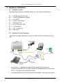
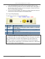
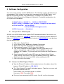
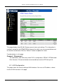
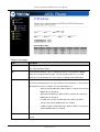
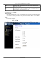
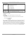
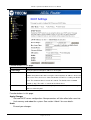
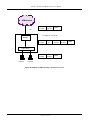
AR1061
1-port ADSL2+ Router
User’s Manual
ISO-9001
Page 1 of 59
TECOM Copyright, 2007
© All Rights Reserved,
M/C: TDSL-1061AR-UM
DC: 960910B-2
AR1061 1-port Ethernet ADSL2+ Router User‘s Manual
FCC Statement
This equipment generates, uses and can radiate radio frequency energy and, if not installed and
used in accordance with the instructions in this manual, may cause interference to radio
communications. This equipment as been tested and found to comply with the limits for a Class
B computing device pursuant to Subpart J of Part 15 of FCC rules, which are designed to provide
reasonable protection against radio interference when operated in a commercial environment.
Operation of this equipment in a residential area is likely to cause interference, in which case the
user, at is own expense, will be required to take whatever measures are necessary to correct the
interface.
CE Declaration of Conformity
This equipment complies with the requirements relating to electromagnetic compatibility,
EN55022 class B for ITE and EN 50082-1. This meets the essential protection requirements of
the European Council Directive 89/336/EEC on the approximation of the laws of the Member
States relating to electromagnetic compatibility.
Environment
The device you have purchased, as well as any used batteries must not be disposed of with
household waste. You should return these to your distributor if they are able to replace or
dispose of them in an approved recycling centre.
Trademarks
Windows 98/2000/XT/NT™ and Internet Explorer™ are registered trademarks of Microsoft
Corporation. All other company, brand and product names, like Netscape Navigator™ are
trademarks or registered trademarks of their respective owners.
!
WARNING!
1. Read all installation instructions carefully before connecting the device to its power source.
2. To reduce the risk of electric shock, do not remove the cover from this device or attempt to
dismantle it. Opening or removing covers may expose you to dangerous voltage levels.
Equally, incorrect reassembly could cause electric shock on re-use of the appliance.
3. Do not expose this device to Fire, direct sunlight or excessive heat.
4. Do not expose the device to rain or moisture and do not allow it to come into contact with
water.
5. Do not install the this device in an environment likely to present a THREAT OF IMPACT.
6. You may clean this device using a fine damp cloth. Never use solvents (such as
trichloroethylene or acetone), which may damage the device’s plastic surface. Never spray
this device with any cleaning product whatsoever.
7. Take care not to scratch the surface of plastic housings.
8. The device is designed to work in temperatures from 5oC to 40oC.
9. The this device must be installed at least 1 meter from radio frequency equipment, such as
TVs, radios, hi-fi or video equipment (which radiate electromagnetic fields).
10. Do not connect the LAN/PC port to any network other than an Ethernet network.
11. Do not attempt to upgrade your this device in an unstable power environment. This could
cause unexpected issues.
12. Do not work on the system or connect or disconnect cables during lightning storms.
13. Children don't recognize the risks of electrical appliances. Therefore use or keep this device
only under supervision of adults or out of the reach from children.
14. No repair can by performed by the end user, if you experience trouble with this equipment,
for repair or warranty information, please contact your supplier.
Page 2 of 59
AR1061 1-port Ethernet ADSL2+ Router User‘s Manual
Contents
1
Introduction ............................................................................................................ 4
2
System Overview ................................................................................................... 4
3
4
5
2.1
General Description ............................................................................................................ 4
2.2
Specifications ...................................................................................................................... 5
Hardware Installation ............................................................................................. 6
3.1
Package Content ................................................................................................................. 6
3.2
Hardware Setup Procedure ................................................................................................. 6
3.3
The I/O Port Definition ......................................................................................................... 7
3.4
The LED Indicator Definition ............................................................................................... 8
Software Configuration ....................................................................................... 10
4.1
Set your PC’s Ethernet port .............................................................................................. 10
4.2
Access the Web Page of Router ....................................................................................... 10
4.3
LAN Configuration ............................................................................................................. 11
4.4
WAN Configuration ............................................................................................................ 12
4.5
Services Configuration ...................................................................................................... 16
4.6
Advance Configuration ...................................................................................................... 31
4.7
Diagnostic .......................................................................................................................... 36
4.8
Admin ................................................................................................................................ 40
4.9
Statistics ............................................................................................................................ 46
4.10
Bridge Mode ...................................................................................................................... 48
4.11
MER(Mac Encapsulating Routing) Mode .......................................................................... 49
4.12
PPPoE Mode ..................................................................................................................... 50
4.13
PPPoA Mode ..................................................................................................................... 51
4.14
1483 Routed Mode ............................................................................................................ 52
Appendix .............................................................................................................. 53
Appendix A: Protocol Stacks ................................................................................................................ 53
Appendix B: Mapping PVCs to VLANs ................................................................................................ 58
Page 3 of 59
AR1061 1-port Ethernet ADSL2+ Router User‘s Manual
1 Introduction
The AR1061 is an ADSL2+ router that can be used to connect to a twisted copper
pair ADSL2+ broadband network. The AR1061 is backwards compatible to all ADSL
modulation technology including G.lite, G.dmt, T1.413, ADSL2 and ADSL2+. AR1061
also supports various internet service provider networks via common WAN protocol such
as PPPOE, PPPOA, Bridge/MER 1483 modes. With advanced features such as remote
configuration, the AR1061 reduces provisioning, maintenance and deployment
overheads and ensures a hassle free user experience. Leveraging adoption of Annex-M
DSL technology, the AR1061 is capable to provide increased upstream rates to better
fulfill growing demand from the SOHO/SMB user. Compliant to Annex L technology, the
AR1061 can reach users in a larger service radius increasing the operators’ Central
Office user density. The AR1061 is a reliable and full-featured ADSL2+ router capable of
supporting data traffic and IP services which allows for minimum overhead deployment.
This User’s Manual mainly contains the guidance to install and configure this ADSL2+
Router using the Web GUI.
2 System Overview
2.1 General Description
This AR1061 Router is a high-speed ADSL Ethernet router that is specifically
designed to connect to the Internet and to directly connect to your local area network
(LAN) via high-speed 10/100 Mbps Ethernet, or wireless LAN (WLAN). The ADSL
modem is compatible with the latest ADSL standards, including ADSL2 and ADSL2+,
and supports up to 24 Mbps downstream and 1.5 Mbps upstream to deliver true
broadband speed and throughput.
To ensure fully compatibility, the DSL device was tested with all major DSLAMs, and
support standard 10/100 Mbps Base-T Ethernet interface Auto MDI / MDIX 10/100
Switch function allowing user easily to link to PC or other Switches/Hubs. The DSL
device is an idea solution for multi-users utilizing build-in channel mode (PPPoE/A, IPoA,
IPoE), IP routing, NAT functionalities sharing the ADSL link. The DSL device is also a
perfect solution for the residential users, it supports the users with bridge mode in host
based PPPoE Client.
Page 4 of 59
AR1061 1-port Ethernet ADSL2+ Router User‘s Manual
2.2 Specifications
ADSL Standard
ITU-T G.992.1(G.dmt)
ANSI T1.413 Issue 2
G.992.2 (G.lite)
G.994.1 (G.hs)
Auto-negotiating rate adaptation
ADSL2 G.dmt.bis (G.992.3)
ADSL2 G.lite.bis (G.992.4)
ADSL2+ (G.992.5)
Software Features
RFC-1483/2684 LLC/VC-Mux bridged/routed mode
RFC-1577 Classical IP over ATM
RFC-2516 PPPoE
RFC-2364 PPPoA
ITU-T 1.610 F4/F5 OAM send and receive loop-back
802.1d Spanning-Tree Protocol
DHCP Client/Server/Relay
NAT
RIP v1/v2
DNS Relay Agent
DMZ support
IGMP Proxy/Snooping
Packet Inspection
Protection against Denial of Service attacks
IP Packet Filtering
QoS
Dynamic DNS
Management
Web-based Configuration
Menu-driven Command-line Interpreter
Telnet Remote Management
SNMP v1/v2/Trap
Firmware upgrade through FTP, TFTP and HTTP
Configuration backup/restore
Diagnostic Tool
Page 5 of 59
AR1061 1-port Ethernet ADSL2+ Router User‘s Manual
3 Hardware Installation
3.1 Package Content
Upon opening the gift box of AR1061 Router, you will find the following items.
1 x AR1061 Router Main Unit
1 x 15VDC/500mA power adaptor
1 x CD-ROM
1 x Quick Install Guide
1 x Warranty Card
1 x RJ-45 Ethernet cable
1 x T-Connector
1 x RJ-11 ADSL line
3 x Microfilters
3.2 Hardware Setup Procedure
Referring to the figure below and connect this ADSL router to the ADSL line and
PC.
1.
Connect RJ-11 Telephone wire from AR1061 Router ADSL port to the
2.
T-connector that connects the ADSL line to the DSLAM located at central office.
Thus it is the gate to the world-wide Internet.
An analog telephone can be connected to the Microfilter. This phone can work as
Page 6 of 59
AR1061 1-port Ethernet ADSL2+ Router User‘s Manual
3.
4.
it were connected directly to the PSTN Line (also called as ADSL line now)
Connect RJ-45 Ethernet Cable from your PC to AR1061 Router Ethernet port. If
you have two or more PC systems, you have to prepare a low-density Ethernet
switch or hub for expansion purpose.
Connect the AC Power Adaptor (15V) and then the AR1061 Router will start to run
and connect the Home local network to the Broadband world.
3.3 The I/O Port Definition
The definition for each port is shown in the following Table.
ADSL
RESET
ETHERNET
ON/OFF
POWER
No
Part Name
Description of function
1
POWER
2
3
ON/OFF
ETHERNET
3
4
RESET
ADSL
Please use the standard power adaptor supplied in the package
(15VDC/500mA).
The power On/Off control Switch
RJ-45 Jack 100/10Mbps Ethernet port for connecting to PC/
Notebook/ Switch
Reset the settings to the factory defaults (*)
RJ-11 Jack to connect to Twisted Pair copper network.
(*) To reset the modem to factory default settings, please press the Reset button
in the back (with a pen, for instance) and hold it for at least 10 seconds, then release.
After 10 seconds aprox., the Power LED will become red, which indicates the
MODEM is in process of restarting, and the Ethernet LED will be blinking green.
After another 20 more seconds aprox. all LED indicators will be green, indicating that
the reset has been successfully performed.
Page 7 of 59
AR1061 1-port Ethernet ADSL2+ Router User‘s Manual
3.4 The LED Indicator Definition
The following table is a description of the meaning of the different LEDs on the AR1061:
LED
POWER
Color
Green
Red
ETHERNET
Green
CONEXION
Green
INTERNET
Green
Red
Status
Description
Off
Power Off
Steady
Power On
Blinking or
Steady
Restarting or Failure
Off
No packets in transit through router
Blinking
Packets in transit through router
Off
Steady
No active DSL link
DSL Link active
Blinking
DSL connection in progress
Off
No LAN connection
Steady
Blinking or
Steady
LAN connection established
Establishment of PPP session or it doesn’t have static
WAN IP assigned
The LED sequence is “Power, ETHERNET, CONEXION, and then INTERNET “.
Page 8 of 59
AR1061 1-port Ethernet ADSL2+ Router User‘s Manual
Page 9 of 59
AR1061 1-port Ethernet ADSL2+ Router User‘s Manual
4 Software Configuration
User can change settings via PC’s WEB browser. The following sections describe the set
up procedures. After successful setting, when you power on the AR1061 Router, it will
boot up and connect to ADSL line automatically. The Router can provide a PVC
(Permanent Virtual Channel) for “Bridge test” by default. The default configurations for
the system are listed below.
• LAN IP address: 192.168.1.1, NetMask: 255.255.255.0
• UART setting : 115200bps, 8 bits, no parity, 1 stop bit, no flow control.
• VPI/VCI for ATM : 8/32 for PPPoE
8/36 for PPPoE with Imagnio service
• ADSL Line mode :
Auto-detect.
4.1 Set your PC’s Ethernet port
AR1061 is an ADSL Router which support DHCP and default enable. You also can set
your computer IP Address as 192.168.1.x within the same subnet as AR1061 (default IP
address is 192.168.1.1) and netmask (default netmask is 255.255.255.0). It can be done
thru the following way.
1.
2.
3.
4.
5.
Click start > Control Panel
In the Control Panel, double-click Network Connections
Right-click Local Area Connection the click Properties
Select Internet Protocol (TCP/IP) then click Properties
The TCP/IP Properties windows appear. You can select obtain an IP
address automatically and click OK to have the AR1061 assign your
computer an IP address. Or you can enter the IP within the same subnet as
AR1061.
6. If your Internet Service Provider (ISP) gave you Domain Name System
(DNS) settings, enter them in the Use the following DNS server addresses
fields. If you are not sure of your DNS setting, contact your ISP.
7. Click OK to finish the setting.
4.2 Access the Web Page of Router
Type the Ethernet IP address of the modem/router on the address bar of the
browser. Default IP address is 192.168.1.1.
The “Enter Network Password” dialog box appears. Type the user name and
password and then click OK.
Default admin user name/password is as follows:
Username: 1234 / Password: 1234
Once you have connected to ADSL router. You will see the status page.
Page 10 of 59
AR1061 1-port Ethernet ADSL2+ Router User‘s Manual
This page displays the AR-1061 Router current status and settings. This information is
read-only except for the PPPoE/PPPoA channel for which user can connect/disconnect
the channel on demand. Click the “Refresh” button to update the status
Function buttons in this page:
Connect / Disconnect
The two buttons take effect only when PVC is configured as PPPoE / PPPoA mode.
Click Connect / Disconnect button to connect/disconnect the PPP dial up link.
4.3 LAN Configuration
This page shows the current setting of LAN interface. You can set IP address, subnet
mask for LAN interface in this page.
Page 11 of 59
AR1061 1-port Ethernet ADSL2+ Router User‘s Manual
Fields in this page:
Field
Description
IP Address
The IP address your LAN hosts use to identify the device’s LAN port.
Subnet Mask
LAN subnet mask.
Secondary IP
The secondary IP address assignment for the device’s LAN port.
Function buttons in this page:
Apply Changes
Click to save the setting to the configuration. New parameters will take effect after
save into flash memory and reboot the system. See section “Admin” for save details.
Undo
Discard your changes.
4.4 WAN Configuration
There are three sub-menus for WAN configuration: [Channel Comfit], [ATM Settings],
and [ADSL Settings].
Channel Configuration
ADSL modem/router comes with 8 ATM Permanent Virtual Channels (PVCs) at the most.
There are mainly three operations for each of the PVC channels: add, delete and modify.
And there are several channel modes to be selected for each PVC channel. For each of
Page 12 of 59
AR1061 1-port Ethernet ADSL2+ Router User‘s Manual
the channel modes, the setting is quite different accordingly. Please refer to the section –
Channel Mode Configuration for details.
Function buttons in this page:
Add
Click Add to complete the channel setup and add this PVC channel into
configuration.
Modify
Select an existing PVC channel by clicking the radio button at the Select column of
the Current ATM VC Table before we can modify the PVC channel. After selecting
a PVC channel, we can modify the channel configuration at this page. Click Modify
to complete the channel modification and apply to the configuration.
Delete
Select an existing PVC channel to be deleted by clicking the radio button at the
Select column of the Current ATM VC Table. Click Delete to delete this PVC
channel from configuration.
ATM Setting
The page is for ATM PVC QoS parameters setting. The DSL device support 4 QoS
mode —UBR/CBR/rt-VBR/nrt-VBR.
Page 13 of 59
AR1061 1-port Ethernet ADSL2+ Router User‘s Manual
Fields in this page:
Field
Description
VPI
Virtual Path Identifier. This is read-only field and is selected on the Select column
in the Current ATM VC Table.
VCI
Virtual Channel Identifier. This is read-only field and is selected on the Select
column in the Current ATM VC Table. The VCI, together with VPI, is used to
identify the next destination of a cell as it passes through to the ATM switch.
QoS
Quality of Server, a characteristic of data transmission that measures how
accurately and how quickly a message or data is transferred from a source host to
a destination host over a network. The four QoS options are:
−
UBR (Unspecified Bit Rate): When UBR is selected, the SCR and
MBS fields are disabled.
−
CBR (Constant Bit Rate): When CBR is selected, the SCR and
MBS fields are disabled.
−
nrt-VBR (non-real-time Variable Bit Rate): When nrt-VBR is
selected, the SCR and MBS fields are enabled.
−
rt-VBR (real-time Variable Bit Rate): When rt-VBR is selected, the
SCR and MBS fields are enabled.
PCR
Peak Cell Rate, measured in cells/sec., is the cell rate which the source may never
exceed.
Page 14 of 59
AR1061 1-port Ethernet ADSL2+ Router User‘s Manual
SCR
Sustained Cell Rate, measured in cells/sec., is the average cell rate over the
duration of the connection.
MBS
Maximum Burst Size, a traffic parameter that specifies the maximum number of
cells that can be transmitted at the peak cell rate.
Function buttons in this page:
Apply Changes
Set new PVC QoS mode for the selected PVC. New parameters will take effect after
save into flash memory and reboot the system. See section “Admin” for save details.
Undo
Discard your settings.
ADSL Setting
The ADSL setting page allows you to select any combination of DSL training modes.
Page 15 of 59
AR1061 1-port Ethernet ADSL2+ Router User‘s Manual
Fields in this page:
Field
Description
ADSL modulation
Choose preferred xDSL standard protocols.
G.lite : G.992.2 Annex A
G.dmt : G.992.1 Annex A
T1.413 : T1.413 issue #2
ADSL2 : G.992.3 Annex A
ADSL2+ : G.992.5 Annex A
AnnexL Option
Enable/Disable ADSL2/ADSL2+ Annex L capability.
AnnexM Option
Enable/Disable ADSL2/ADSL2+ Annex M capability.
ADSL Capability
“Bit-swap Enable” : Enable/Disable bit-swap capability.
“SRA Enable” : Enable/Disable SRA (seamless rate adaptation) capability.
Function buttons in this page:
Tone Mask
Choose tones to be masked. Masked tones will not carry any data.
Apply Changes
Click to save the setting to the configuration and the modem will be retrained.
4.5 Services Configuration
DHCP Mode
You can configure your network and DSL device to use the Dynamic Host Configuration
Protocol (DHCP). This page provides DHCP instructions for implementing it on your
network by selecting the role of DHCP protocol that this device wants to play. There are
two different DHCP roles that this device can act as: DHCP Serve and DHCP Relay.
When acting as DHCP server, you can setup the server parameters at the DHCP Server
page; while acting as DHCP Relay, you can setup the relay at the DHCP Relay page.
Page 16 of 59
AR1061 1-port Ethernet ADSL2+ Router User‘s Manual
DHCP Server Configuration
By default, the device is configured as a DHCP server, with a predefined IP address pool
of 192.168.1.33 through 192.168.1.254 (subnet mask 255.255.255.0).
Page 17 of 59
AR1061 1-port Ethernet ADSL2+ Router User‘s Manual
Function buttons in this page:
Field
Description
IP Pool Range
Specify the lowest and highest addresses in the pool.
Max Lease Time
The Lease Time is the amount of time that a network user is allowed to maintain a
network connection to the device using the current dynamic IP address. At the end
of the Lease Time, the lease is either renewed or a new IP is issued by the DHCP
server. The amount of time is in units of seconds. The default value is 86400
seconds (1 day). The value –1 stands for the infinite lease.
Domain Name
A user-friendly name that refers to the group of hosts (subnet) that will be assigned
addresses from this pool.
Function buttons in this page:
Apply Changes
Set new DHCP server configuration. New parameters will take effect after save into
flash memory and reboot the system. See section “Admin” for save details.
Undo
Discard your changes.
Page 18 of 59
AR1061 1-port Ethernet ADSL2+ Router User‘s Manual
DHCP Relay Configuration
Some ISPs perform the DHCP server function for their customers’ home/small office
network. In this case, you can configure this device to act as a DHCP relay agent. When
a host on your network requests Internet access, the device contacts your ISP to obtain
the IP configuration, and then forward that information to the host. You should set the
DHCP mode after you configure the DHCP relay.
Fields in this page:
Field
Description
DHCP Server
Specify the IP address of your ISP’s DHCP server. Requests for IP information
Address
from your LAN will be passed to the default gateway, which should route the
request appropriately.
Function button in this page
Apply Changes
Click to save the setting to the configuration.
DNS Configuration
There are two submenus for the DNS Configuration: [DNS Server] and [Dynamic DNS]
4.5.1.1
DNS Server
This page is used to select the way to obtain the IP addresses of the DNS servers.
Page 19 of 59
AR1061 1-port Ethernet ADSL2+ Router User‘s Manual
Field
Description
Attain DNS
Automatically
Select this item if you want to use the DNS servers obtained by the
WAN interface via the auto-configuration mechanism.
Set DNS Manually Select this item to configure up to three DNS IP addresses.
Function buttons in this page:
Apply Changes
Set new DNS relay configuration. New parameters will take effect after save into
flash memory and reboot the system. See section “Admin” for save details.
Undo
Discard your changes.
4.5.1.2
Dynamic DNS
Each time your device connects to the Internet, your ISP assigns a different IP address
to your device. In order for you or other users to access your device from the WAN-side,
you need to manually track the IP that is currently used. The Dynamic DNS feature
allows you to register your device with a DNS server and access your device each time
using the same host name. The Dynamic DNS page allows you to enable/disable the
Dynamic DNS feature.
Page 20 of 59
AR1061 1-port Ethernet ADSL2+ Router User‘s Manual
On the Dynamic DNS page, configure the following fields:
Field
Description
Enable
Check this item to enable this registration account for the DNS
server.
DDNS provider
There are two DDNS providers to be selected in order to register
your device with: DynDNS and TZO. A charge may occur depends
on the service you select.
Hostname
Domain name to be registered with the DDNS server.
Interface
This field defaults to your device’s WAN interface over which your
device will be accessed.
Username
User-name assigned by the DDNS service provider.
Password
Password assigned by the DDNS service provider.
Function buttons in this page:
Add
Click Add to add this registration into the configuration.
Remove
Select an existing DDNS registration by clicking the radio button at the Select
Page 21 of 59
AR1061 1-port Ethernet ADSL2+ Router User‘s Manual
column of the Dynamic DNS Table. Click Remove button to remove the selected
registration from the configuration.
Firewall Configuration
Firewall contains several features that are used to deny or allow traffic from passing
through the device.
4.5.1.3
IP/Port Filtering
The IP/Port filtering feature allows you to deny/allow specific services or applications in
the forwarding path.
Fields on the first setting block:
Field
Description
Outgoing Default
Specify the default action on the LAN to WAN forwarding path.
Action
Incoming Default
Specify the default action on the WAN to LAN forwarding path.
Action
Function button for this first setting block:
Apply Changes
Click to save the setting of default actions to the configuration.
Page 22 of 59
AR1061 1-port Ethernet ADSL2+ Router User‘s Manual
Fields on the second setting block:
Field
Description
Rule Action
Deny or allow traffic when matching this rule.
Direction
Traffic forwarding direction.
Protocol
There are 3 options available: TCP, UDP and ICMP.
Src IP Address
The source IP address assigned to the traffic on which filtering is
applied.
Src Subnet Mask Subnet-mask of the source IP.
Src Port
Starting and ending source port numbers.
Dst IP Address
The destination IP address assigned to the traffic on which filtering is
applied.
Dst Subnet Mask Subnet-mask of the destination IP.
Dst Port
Starting and ending destination port numbers.
Function buttons for this second setting block:
Apply Changes
Click to save the rule entry to the configuration.
Function buttons for the Current Filter Table:
Delete Selected
Delete selected filtering rules from the filter table. You can click the checkbox at the
Select column to select the filtering rule.
Delete All
Delete all filtering rules from the filter table.
Page 23 of 59
AR1061 1-port Ethernet ADSL2+ Router User‘s Manual
4.5.1.4
MAC Filtering
The MAC filtering feature allows you to define rules to allow or deny frames through the
device based on source MAC address, destination MAC address, and traffic direction.
Fields on the first setting block:
Field
Description
Outgoing Default
Specify the default action on the LAN to WAN bridging/forwarding path.
Action
Incoming Default
Specify the default action on the WAN to LAN bridging/forwarding path.
Action
Function button for this first setting block:
Apply Changes
Click to save the setting of default actions to the configuration.
Fields on the second setting block:
Field
Description
Rule Action
Deny or allow traffic when matching this rule.
Direction
Traffic bridging/forwarding direction.
Page 24 of 59
AR1061 1-port Ethernet ADSL2+ Router User‘s Manual
Src MAC Address
The source MAC address. It must be xxxxxxxxxxxx format. Blanks can be used in
the MAC address space and are considered as don’t care.
Dst MAC Address
The destination MAC address. It must be xxxxxxxxxxxx format. Blanks can be
used in the MAC address space and are considered as don’t care.
Function buttons for this second setting block:
Apply Changes
Click to save the rule entry to the configuration.
Function buttons for the Current Filter Table:
Delete Selected
Delete selected filtering rules from the filter table. You can click the checkbox at the
Select column to select the filtering rule.
Delete All
Delete all filtering rules from the filter table.
4.5.1.5
Port Forwarding
Firewall keeps unwanted traffic from the Internet away from your LAN computers. Add a
Port Forwarding entry will create a tunnel through your firewall so that the computers on
the Internet can communicate to one of the computers on your LAN on a single port.
Page 25 of 59
AR1061 1-port Ethernet ADSL2+ Router User‘s Manual
Fields in this page:
Field
Description
Enable Port
Check this item to enable the port-forwarding feature.
Forwarding
Protocol
There are 3 options available: TCP, UDP and Both.
Enable
Check this item to enable this entry.
Local IP Address
IP address of your local server that will be accessed by Internet.
Port
The destination port number that is made open for this application on the
LAN-side.
Remote IP Address
The source IP address from which the incoming traffic is allowed. Leave blank for
all.
The destination port number that is made open for this application on the
External Port
WAN-side
Select the WAN interface on which the port-forwarding rule is to be applied.
Interface
Function buttons for the setting block:
Apply Changes
Click to save the rule entry to the configuration.
Function buttons for the Current Port Forwarding Table:
Delete Selected
Delete the selected port forwarding rules from the forwarding table. You can click
the checkbox at the Select column to select the forwarding rule.
Delete All
Delete all forwarding rules from the forwarding table.
4.5.1.6
DMZ
A DMZ (Demilitarized Zone) allows a single computer on your LAN to expose ALL of its
ports to the Internet. Enter the IP address of that computer as a DMZ (Demilitarized Zone)
host with unrestricted Internet access. When doing this, the DMZ host is no longer
behind the firewall.
Page 26 of 59
AR1061 1-port Ethernet ADSL2+ Router User‘s Manual
Fields in this page:
Field
Description
Enable DMZ
Check this item to enable the DMZ feature.
DMZ Host IP Address IP address of the local host. This feature sets a local host to be exposed to the
Internet.
Function buttons in this page:
Apply Changes
Click to save the setting to the configuration.
IGMP Proxy Configuration
Multicasting is useful when the same data needs to be sent to more than one hosts.
Using multicasting as opposed to sending the same data to the individual hosts uses
less network bandwidth. The multicast feature also enables you to receive multicast
video stream from multicast servers.
IP hosts use Internet Group Management Protocol (IGMP) to report their multicast group
memberships to neighboring routers. Similarly, multicast routers use IGMP to discover
which of their hosts belong to multicast groups. This device supports IGMP proxy that
handles IGMP messages. When enabled, this device acts as a proxy for a LAN host
Page 27 of 59
AR1061 1-port Ethernet ADSL2+ Router User‘s Manual
making requests to join and leave multicast groups, or a multicast router sending
multicast packets to multicast group on the WAN side.
When a host wishes to join a multicast group, it sends IGMP REPORT message to the
device’s IGMP downstream interface. The proxy sets up a multicast route for the
interface and host requesting the video content. It then forwards the Join to the upstream
multicast router. The multicast IP traffic will then be forwarded to the requesting host. On
a leave, the proxy removes the route and then forwards the leave to the upstream
multicast router.
The IGMP Proxy page allows you to enable multicast on WAN and LAN interfaces. The
LAN interface is always served as downstream IGMP proxy, and you can configure one
of the available WAN interfaces as the upstream IGMP proxy.
Upstream: The interface that IGMP requests from hosts are sent to the
multicast router.
Downstream: The interface data from the multicast router are sent to hosts in
the multicast group database.
Fields in this page:
Field
Description
IGMP Proxy
Enable/disable IGMP proxy feature
Proxy Interface
The upstream WAN interface is selected here.
Page 28 of 59
AR1061 1-port Ethernet ADSL2+ Router User‘s Manual
Function buttons in this page:
Apply Changes
Click to save the setting to the configuration.
Undo
Discard your settings.
RIP Configuration
RIP is an Internet protocol you can set up to share routing table information with other
routing devices on your LAN, at your ISP’s location, or on remote networks connected to
your network via the ADSL line.
Most small home or office networks do not need to use RIP; they have only one router,
such as the ADSL Router, and one path to an ISP. In these cases, there is no need to
share routes, because all Internet data from the network is sent to the same ISP
gateway.
You may want to configure RIP if any of the following circumstances apply to your
network:
Your home network setup includes an additional router or RIP-enabled PC
(other than the ADSL Router). The ADSL Router and the router will need to
communicate via RIP to share their routing tables.
Your network connects via the ADSL line to a remote network, such as a
corporate network. In order for your LAN to learn the routes used within your
corporate network, they should both be configured with RIP.
Your ISP requests that you run RIP for communication with devices on their
network.
Page 29 of 59
AR1061 1-port Ethernet ADSL2+ Router User‘s Manual
Fields on the first setting block:
Field
Description
RIP
Enable/disable RIP feature.
Function buttons for the second setting block in this page:
Apply Changes
Click to save the setting of this setting block to the system configuration
Fields on the second setting block:
Field
Description
Interface
The name of the interface on which you want to enable RIP.
Receive Mode
Indicate the RIP version in which information must be passed to the DSL device in
order for it to be accepted into its routing table.
Send Mode
Indicate the RIP version this interface will use when it sends its route information
to other devices.
Function buttons for the second setting block in this page:
Add
Add a RIP entry and the new RIP entry will be display in the table
Delete Selected Entry
Delete a selected RIP entry. The RIP entry can be selected on the Select column of
the RIP Config Table.
Page 30 of 59
AR1061 1-port Ethernet ADSL2+ Router User‘s Manual
4.6 Advance Configuration
ARP table
You can see the show list of learned MAC addresses through ARP in this page.
Bridging
You can enable/disable Spanning Tree Protocol and set MAC address aging time in this
page.
Fields in this page:
Field
Description
Page 31 of 59
AR1061 1-port Ethernet ADSL2+ Router User‘s Manual
Set the Ethernet address ageing time, in seconds. After [Ageing Time] seconds
Ageing Time
of not having seen a frame coming from a certain address, the bridge will time
out (delete) that address from Forwarding Database (fdb).
802.1d Spanning Tree
Enable/disable the spanning tree protocol
Function buttons in this page:
Apply Changes
Save this bridge configuration. New configuration will take effect after saving into
flash memory and rebooting the system. See section “Admin” for details.
Show MACs
List MAC address in forwarding table.
Routing
The Routing page enables you to define specific route for your Internet and network data.
Most users do not need to define routes. On a typical small home or office LAN, the
existing routes that set up the default gateways for your LAN hosts and for the DSL
device provide the most appropriate path for all your Internet traffic.
On your LAN hosts, a default gateway directs all Internet traffic to the LAN
port(s) on the DSL device. Your LAN hosts know their default gateway either
because you assigned it to them when you modified your TCP/IP properties, or
because you configured them to receive the information dynamically from a
server whenever they access the Internet.
On the DSL device itself, a default gateway is defined to direct all outbound
Internet traffic to a route at your ISP. The default gateway is assigned either
automatically by your ISP whenever the device negotiates an Internet access,
or manually by user to setup through the configuration.
You may need to define routes if your home setup includes two or more networks or
subnets, if you connect to two or more ISP services, or if you connect to a remote
corporate LAN.
Page 32 of 59
AR1061 1-port Ethernet ADSL2+ Router User‘s Manual
Fields in this page:
Field
Description
Enable
Check to enable the selected route or route to be added.
Destination
The network IP address of the subnet. The destination can be specified as the IP
address of a subnet or a specific host in the subnet. It can also be specified as all
zeros to indicate that this route should be used for all destinations for which no
other route is defined (this is the route that creates the default gateway).
Subnet Mask
The network mask of the destination subnet. The default gateway uses a mask of
0.0.0.0.
Next Hop
The IP address of the next hop through which traffic will flow towards the
destination subnet.
Metric
Defines the number of hops between network nodes that data packets travel. The
default value is 0, which means that the subnet is directly one hop away on the
local LAN network.
Interface
The WAN interface to which a static routing subnet is to be applied.
Function buttons in this page:
Add Route
Add a user-defined destination route.
Update
Update the selected destination route on the Static Route Table.
Delete Selected
Page 33 of 59
AR1061 1-port Ethernet ADSL2+ Router User‘s Manual
Delete a selected destination route on the Static Route Table.
Show Routes
Click this button to view the DSL device’s routing table. The IP Route Table displays,
as shown in Figure.
SNMP Configuration
Simple Network Management Protocol (SNMP) is a troubleshooting and management
protocol that uses the UDP protocol on port 161 to communicate between clients and
servers. The DSL device can be managed locally or remotely by SNMP
protocol
Page 34 of 59
AR1061 1-port Ethernet ADSL2+ Router User‘s Manual
Fields in this page:
Field
Description
System Description
System description of the DSL device.
System Contact
Contact person and/or contact information for the DSL device.
System Name
An administratively assigned name for the DSL device.
System Location
The physical location of the DSL device.
System Object ID
Vendor object identifier. The vendor’s authoritative identification of the network
management subsystem contained in the entity.
Trap IP Address
Destination IP address of the SNMP trap.
Community name
Name of the read-only community. This read-only community allows read
(read-only)
operation to all objects in the MIB.
Community name
Name of the write-only community. This write-only community allows write
(write-only)
operation to the objects defines as read-writable in the MIB.
Function buttons in this page:
Apply Changes
Save SNMP configuration. New configuration will take effect after saving into flash
memory and rebooting the system. See section “Admin” for details.
IP QoS
Page 35 of 59
AR1061 1-port Ethernet ADSL2+ Router User‘s Manual
Remote Access
The Remote Access function can secure remote host access to your DSL device from
LAN and WLAN interfaces for some services provided by the DSL device.
Fields in this page:
Field
Description
LAN
Check/un-check the services on the LAN column to allow/un-allow the services
access from LAN side; and “WAN”:
WAN
Check/un-check the services on the WAN column to allow/un-allow the services
access from WAN side.
WAN Port
This field allows the user to specify the port of the corresponding service. Take the
HTTP service for example; when it is changed to 8080, the HTTP server address
for the WAN side is http://dsl_addr:8080, where the dsl_addr is the WAN side IP
address of the DSL device.
4.7 Diagnostic
The DSL device supports some useful diagnostic tools.
Ping
Once you have your DSL device configured, it is a good idea to make sure you can ping
Page 36 of 59
AR1061 1-port Ethernet ADSL2+ Router User‘s Manual
the network. A ping command sends a message to the host you specify. If the host
receives the message, it sends messages in reply. To use it, you must know the IP
address of the host you are trying to communicate with and enter the IP address in the
Host Address field. Click Go! To start the ping command, the ping result will then be
shown in this page.
Fields in this page:
Field
Description
Host Address
The IP address you want to ping.
ATM Loopback
In order to isolate the ATM interface problems, you can use ATM OAM loopback cells to
verify connectivity between VP/VC endpoints, as well as segment endpoints within the
VP/VC. ATM uses F4 and F5 cell flows as follows:
F4: used in VPs
F5: used in VCs
An ATM connection consists of a group of points. This OAM implementation provides
management for the following points:
Connection endpoint: the end of a VP/VC connection where the ATM cell are
terminated
Segment endpoint: the end of a connection segment
This page allows you to use ATM ping, which generates F5 segment and end-to-end
loop-back cells to test the reachability of a segment endpoint or a connection endpoint.
Page 37 of 59
AR1061 1-port Ethernet ADSL2+ Router User‘s Manual
Fields in this page:
Field
Description
Select PVC
Select the PVC channel you want to do the loop-back diagnostic.
Flow Type
The ATM OAM flow type. The selection can be F5 Segment or F5 End-to-End.
Loopback Location ID The loop-back location ID field of the loop-back cell. The default value is all 1s
(ones) to indicate the endpoint of the segment or connection.
ADSL
This page shows the ADSL diagnostic result. Click Start button to start the ADSL
diagnostic.
Page 38 of 59
AR1061 1-port Ethernet ADSL2+ Router User‘s Manual
Diagnostic Test
The Diagnostic Test page shows the test results for the connectivity of the physical layer
and protocol layer for both LAN and WAN sides.
Page 39 of 59
AR1061 1-port Ethernet ADSL2+ Router User‘s Manual
Fields in this page:
Field
Description
Select the Internet
The available WAN side interfaces are listed. You have to select one for the WAN
Connection
side diagnostic.
4.8 Admin
Commit / Reboot
Whenever you use the Web configuration to change system settings, the changes are
initially placed in temporary storage. These changes will be lost if the device is reset or
turn off. To save your change for future use, you can use the commit function.
Function buttons in this page:
Commit and Reboot
Whenever you use the web console to change system settings, the changes are
initially placed in temporary storage. To save your changes for future use, you can
use the Commit/Reboot function. This function saves your changes from RAM to
flash memory and reboot the system.
IMPORTANT!
Do not turn off your modem or press the Reset button while this procedure is in progress.
Page 40 of 59
AR1061 1-port Ethernet ADSL2+ Router User‘s Manual
Backup/Restore
This page allows you to backup and restore your configuration into and from file in your
host.
Password
The first time you log into the system, you use the default password. There are two-level
logins: 1234 and user. The 1234 and user password configuration allows you to change
the password for administrator and user.
Page 41 of 59
AR1061 1-port Ethernet ADSL2+ Router User‘s Manual
Fields in this page:
Field
Description
User Name
Selection of user levels are: admin and user.
Old Password
Enter the old password for this selected login.
New Password
Enter the new password here.
Confirmed Password Enter the new password here again to confirm.
Upgrade Firmware
To upgrade the firmware for the DSL device:
−
Click the Browse button to select the firmware file.
−
Confirm your selection.
−
Click the Upload button to start upgrading.
IMPORTANT! Do not turn off your DSL device or press the Reset button while this procedure is in
progress.
ACL
The Access Control List (ACL) is a list of permissions attached to the DSL device. The
list specifies who is allowed to access this device. If ACL is enabled, all hosts cannot
access this device except for the hosts with IP address in the ACL table.
Page 42 of 59
AR1061 1-port Ethernet ADSL2+ Router User‘s Manual
Fields in this page:
Field
Description
ACL Capability
Enable/disable the ACL function
Enable
Check to enable this ACL entry
Interface
Select the interface domain: LAN or WAN
IP Address
Enter the IP address that allow access to this device.
Time Zone
Simple Network Timing Protocol (SNTP) is a protocol used to synchronize the system
time to the public SNTP servers. The DSL device supports SNTP client functionality in
compliance with IETF RFC2030. SNTP client functioning in daemon mode which issues
sending client requests to the configured SNTP server addresses periodically can
configure the system clock in the DSL device
Page 43 of 59
AR1061 1-port Ethernet ADSL2+ Router User‘s Manual
Fields in this page:
Field
Description
Current Time
The current time of the specified time zone. You can set the current time by
yourself or configured by SNTP.
Time Zone Select
The time zone in which the DSL device resides.
Enable SNTP client
Enable the SNTP client to update the system clock.
update
SNTP server
The IP address or the host name of the SNTP server. You can select from the list
or set it manually.
TR-069 Config.
TR-069 is a protocol for communication between a CPE and Auto-Configuration Server
(ACS). The CPE TR-069 configuration should be well defined to be able to communicate
with the remote ACS.
Page 44 of 59
AR1061 1-port Ethernet ADSL2+ Router User‘s Manual
Fields in this page:
ACS Field
Description
URL
ACS URL. For example, http://10.0.0.1:80 https://10.0.0.1:443
User Name
The username the DSL device should use when connecting to the ACS.
Password
The password the DSL device should use when connecting to the ACS.
Periodic Inform Enable When this field is enabled, the DSL device will send an Inform RPC to the ACS
server at the system startup, and will continue to send it periodically at an interval
defined in Periodic Inform Interval field; When this field is disabled, the DSL
device will only send Inform RPC to the ACS server once at the system startup.
Periodic Inform Interval Time interval in second to send Inform RPC.
Connection Request
Description
Field
User Name
The username the remote ACS should use when connecting to this device.
Password
The password the remote ACS should use when connecting to this device.
Path
The path of the device ConnectionRequestURL. The device
ConnectionRequestURL should be configured based on the Device_IP, Path and
Page 45 of 59
AR1061 1-port Ethernet ADSL2+ Router User‘s Manual
Port as follows:
http://Device_IP:Port/Path
Port
The port of the device ConnectionRequestURL.
Note: Please enable the Auto-Execution to enable the TR-069 process
4.9
Statistics
The DSL device shows the different layer of network statistics information.
Interfaces
You can view statistics on the processing of IP packets on the networking interfaces.
You will not typically need to view this data, but you may find it helpful when working with
your ISP to diagnose network and Internet data transmission problems.
To display updated statistics showing any new data since you opened this page, click
Refresh.
ADSL
This page shows the ADSL line statistic information.
Page 46 of 59
AR1061 1-port Ethernet ADSL2+ Router User‘s Manual
Page 47 of 59
AR1061 1-port Ethernet ADSL2+ Router User‘s Manual
Channel Mode Configuration
ADSL router supports multiple channel operation modes. This section will show
procedures to configure the router.
4.10 Bridge Mode
1. Open the WEB page at “WAN interface/Channel Configuration”.
2. Select the Channel Mode to “1483 Bridged”. Set the parameters VPI/VCI and
Encapsulation mode according to the CO DSLAM setting.
3. Click “Add” button to add this channel into VC table.
4. Open the WEB page at “Admin/ Commit/Reboot”. Press “Commit” to save the
settings into flash memory.
5. The new settings will take effect after reboot the system.
Page 48 of 59
AR1061 1-port Ethernet ADSL2+ Router User‘s Manual
4.11 MER(Mac Encapsulating Routing) Mode
1. Open the WEB page at “WAN interface/Channel Configuration”.
2. Select the Channel Mode to “1483 MER”. Set the parameters VPI/VCI and
Encapsulation mode according to the CO DSLAM setting.
3. Set “Local IP Address:” according to the IP that ISP assign for your router. Set
“Remote IP Address” to the ISP’s gateway.
4. Click “Add” button to add this channel into VC table.
5. Open the WEB page at “Admin/ Commit/Reboot”. Press “Commit” to save the
settings into flash memory.
6. The new settings will take effect after reboot the system.
Page 49 of 59
AR1061 1-port Ethernet ADSL2+ Router User‘s Manual
4.12 PPPoE Mode
1. Open the WEB page at “WAN interface/Channel Configuration”.
2. Select the Channel Mode to “PPPoE”. Set the parameters VPI/VCI and
Encapsulation mode according to the CO DSLAM setting.
3. Enter user/password from your ISP.
4. Click “Add” button to add this channel.
5. Enable DHCP server to allow the local PCs share the PPP connection.
Reference to section 4.6.1 DHCP Server Configuration.
6. Set DNS address from your ISP. Reference to section 4.6.2 DNS Configuration.
7. Open the WEB page at “Admin/ Commit/Reboot”. Press “Commit” to save the
settings into flash memory.
8. The new settings will take effect after reboot the system.
Page 50 of 59
AR1061 1-port Ethernet ADSL2+ Router User‘s Manual
4.13 PPPoA Mode
1. Open the WEB page at “WAN interface/Channel Configuration”.
2. Select the Channel Mode to “PPPoA”. Set the parameters VPI/VCI and
Encapsulation mode according to the CO DSLAM setting.
3. Enter user/password from your ISP.
4. Click “Add” button to add this channel.
5. Enable DHCP server to allow the local PCs share the PPP connection.
Reference to section 4.6.1 DHCP Server Configuration.
6. Set DNS address from your ISP. Reference to section 4.6.2 DNS Configuration.
7. Open the WEB page at “Admin/ Commit/Reboot”. Press “Commit” to save the
settings into flash memory.
8. The new settings will take effect after reboot the system.
Page 51 of 59
AR1061 1-port Ethernet ADSL2+ Router User‘s Manual
4.14 1483 Routed Mode
1. Open the WEB page at “WAN interface/Channel Configuration”.
2. Select the Channel Mode to “1483 Routed”. Set the parameters VPI/VCI and
Encapsulation mode according to the CO DSLAM setting.
3. In WAN IP settings, give the local and remote IP address from your ISP or use
DHCP to get them automatically if your ISP support it. Local IP is the address of
ADSL router. Remote IP is the ISP’s gateway address.
4. Click “Add” button to add this channel.
5. Open the WEB page at “Admin/ Commit/Reboot”. Press “Commit” to save the
settings into flash memory.
6. The new settings will take effect after reboot the system.
For more information or any question, please consult to your supplier for details.
Page 52 of 59
AR1061 1-port Ethernet ADSL2+ Router User‘s Manual
5 Appendix
Appendix A: Protocol Stacks
A.1 1483 Bridged Model
IP
IP
Ethernet
Ethernet
Ethernet
Ethernet
LLC/SNAP
(1483-B)
LLC/SNAP
(1483-B)
AAL5
AAL5
SAR
SAR
ATM
100BaseT
PC
100BaseT
xDSL
ATU-R
xDSL
ATM
ATM
SONET/SDH
SONET/SDH
DSLAM
1483 Bridged Channel Mode Scenario
Page 53 of 59
BRAS
AR1061 1-port Ethernet ADSL2+ Router User‘s Manual
A.2 1483 MER Model
IP
IP
IP
IP
Ethernet
Ethernet
Ethernet
Ethernet
LLC/SNAP
(1483-B)
LLC/SNAP
(1483-B)
AAL5
AAL5
SAR
SAR
ATM
100BaseT
PC
100BaseT
xDSL
ATU-R
xDSL
ATM
ATM
SONET/SDH
SONET/SDH
DSLAM
1483 MER Channel Mode Scenario
Page 54 of 59
BRAS
AR1061 1-port Ethernet ADSL2+ Router User‘s Manual
A.3 PPPoE Model
IP
Ethernet
IP
Ethernet
IP
IP
PPP
PPP
PPPoE
PPPoE
Ethernet
Ethernet
LLC/SNAP
(1483-B)
LLC/SNAP
(1483-B)
AAL5
AAL5
SAR
SAR
ATM
100BaseT
PC
100BaseT
xDSL
ATU-R
xDSL
ATM
ATM
SONET/SDH
SONET/SDH
DSLAM
PPPoE Channel Mode Scenario
Page 55 of 59
BRAS
AR1061 1-port Ethernet ADSL2+ Router User‘s Manual
A.4 PPPoA Model
IP
IP
IP
IP
Ethernet
Ethernet
PPP
PPP
AAL5
AAL5
SAR
SAR
ATM
100BaseT
PC
100BaseT
xDSL
ATU-R
xDSL
ATM
ATM
SONET/SDH
SONET/SDH
DSLAM
PPPoA Channel Mode Scenario
Page 56 of 59
BRAS
AR1061 1-port Ethernet ADSL2+ Router User‘s Manual
A.5 1483 Routed Model
IP
IP
Ethernet
Ethernet
IP
IP
LLC/SNAP
(1483-R)
LLC/SNAP
(1483-R)
AAL5
AAL5
SAR
SAR
ATM
100BaseT
PC
100BaseT
xDSL
ATU-R
xDSL
ATM
ATM
SONET/SDH
SONET/SDH
DSLAM
1483 Routed Channel Mode Scenerio
Page 57 of 59
BRAS
AR1061 1-port Ethernet ADSL2+ Router User‘s Manual
Appendix B: Mapping PVCs to VLANs
The AR1061 Router supports mapping ATM Permanent Virtual Circuits (PVCs) to
VLANs, based on the ATM bridging standards of RFC2684. This feature allows an ATM
PVC to be configured as a bridging interface and used in conjunction with a VLAN.
Figure B.1 illustrates the how the AR1061 Router adds a VLAN ID and tag to packets
subject to PVC-VLAN mapping. In this example, vc3 is mapped to VLAN 20. The
AR1061 Router adds VLAN ID 20 and tag 8100 to packets from vc3.
Page 58 of 59
AR1061 1-port Ethernet ADSL2+ Router User‘s Manual
ATM Network
Ethern
Header
IP
Header
DATA
Vc3
Vc3 mapped to VLAN 20
AR1061
Ethern
Header
VLAN ID
20
Ethern
Header
IP
Header
Tag Type
0x8100
IP
Header
Ether Switch
VLAN 10
DATA
VLAN 20
Figure B.1 Adding a VLAN ID and tag to packets from a PVC
Page 59 of 59
DATA