1
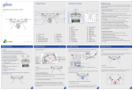
INDEX
1 SUMMARY
1.1
1.2
1.3
1.3.1
1.3.2
1.3.3
1.3.4
1.3.5
SUITABLE LOCATION
RF CARD PERFORMANCE INTRODUCTION
CONSTRUCTION OF ES5020 HOTEL ACCESS CONTROLSYSTEM
IC card electronic access controller
Card types and function
Line concentrator
Card Issuer
System manage software and computer and LAN
2 INSTALLATION AND WIRING
3 OPERATION OF ACCESS CONTROL SYSTEM
3.1
3.2
3.3
3.4
3.5
3.5.1
3.5.2
3.5.4
3.5.5
3.5.6
3.5.7
3.5.8
3.3.9
SOUND AND LIGHT SIGNALS OF ACCESS CONTROLLOR
INITIALIZATION OF READER
INITIALIZATION OF ACCESS CONTROLLOR
SET LOCK FORMAT
DAILY OPERATION
Open Lock
Normal open and Normal close
Telecontrol opening, telecontrol normal open and telecontrol close
Report loss
Forbid
Adjust clock
Record collect
Clear all
1 Summary
ES5020 (IC CARD) Access control system is to be used together with ES9020 hotel
lock system.
This system keeps all function of original ES9020 Hotel Lock system, and it won’t
affect other operations but communication even if communications break off.
1.1 Suitable location
ES5020 Hotel Access control system can be used in grand hotels, intelligent
office building and some other places which needs entrance management.
Normally, ES5020 is more suitable to be installed in entrance door or Passage door,
or outdoor part of a building.
1.3 Main construction of ES5010 Access control system
ES5020 system is mainly composed of electronic access controller, electronic lock,
reader and multifunctional cards, line concentrator, DC power supply, card issuer,
232-422 converter and , computer, LAN and system manage software.
CONTROL
ELETRONICLOCK
POWER
READER
ELECTRONICLOCK
CONTROL
POWER
READER
1.3.1 IC card electronic access controller
ES5020 access controller is composed of power supply, main board and outer shell
etc. Its standard appearance is a normal 210 x 210 electricity controller (Camera Lucida).
It can also be disconnected and re-assembly or change the electricity controller into
Camera obscure etc. In a word, the appearance and construction can be different, but
the electricity circuit and working principle is basically the same.
The Access control system is power supplied by 110V AC. The main board is
supplied by 15V DC voltage output from switch power supply.
When an access control system leaves factory, there is no difference among
controllers except communication address, which is set by move switches on circuit
board. After Access control system is installed, the reader will be connected with the
main board of the Access control system by cable. Initialize it by Cite code Card, Room
Number Card and Clock Card, this process is to set Cite code, serial number to it and
adjust its clock correctly. When IC card pass by the reader, the micro computer inside
the main board read the information of the IC card, to judge the card whether it is legal
by logical analysis (if cite code is correct, Room number is correct time is correct and if
can open the lock etc.), and output various signals to drive the indication light, buzzer
or relay to work. For example, if legal card were read, it will output signal and activate
relay, and therefore drive electric lock open.
Access controller should be connected with line concentrator by one twisted-pair
(8core , style5), so that it can connect with power supply and communicate with
1.3.2 Card types and function
In this system, there are more than 10 kinds of cards with different function and
authority. Below is simple description for various cards
1. 1. Site Card: Set the access Site(Hotel ID) after first installation. Not for opening
lock.
2. 2. Room No Card: Set the room No. On its relating access after first
installation.Not for
opening lock.
3. 3. Clock Card: Set and adjust the inner clock time correct. Not for opening
lock.
4. 4. Initialize Card: To delete all user information except system cipher, room No
and passage mark.
5. 5. Discontinue Card: Forbid the appointed room from being used by a formal
Guest Card. Not for opening lock.
6. 6. Report loss Card: To report loss and forbid one lost card from opening its
authorized locks, make it invalid. Not for opening lock.
7. 7. Emergency Card: Can open all the locks in emergency occasion, even
including deadlocked door. No other card has this function.
8. 8. Master Card: Can open all the accesses.
9. 9. Supervisor Card: Can open all the accesses of the designated floors of one
building
10. 10. Service Card: Can open all the accesses or partial accesses of the designated
floor of a building
11. 11. Unlocking Card: Set the designated access as normal-open status during a
certain period
12. 12. Staff Card: Can open the designated access only one time.
13. 13. Backup Card: Can open the designed access. When the issue card system can’t
work normally, this card can be offered to customer to use. For hotel normal
business each lock should has one backup card.
14. 14. Keycard: Can open designated access.
1.3.3 Line concentrator
This hardware is used to connect with communication line in network. (Please note: it
is different from the line concentrator in LAN)
This line concentrator has several types, and usage should be according to actual
needs.
Its standard configure is 210*210*70 and power supply should be 110V/220V (which is
output from big power UPS in main computer room, it will be easy to overhaul if lines
are set as floors.) Power is 50W (Actually it is smaller.)
The distance better be less than 50m and 5type line will be better. (The resistance of
single line 100m is less than 10O )
Please put the mail line concentrator in the main computer room and put one 5type
line on each floor (Its length should be less than 300m and as shorter as better). Line
concentrators on the same floor can be in series nearly.
1.3.4 Card issuer
Card issuer also can be called as Encoder or Write-Read encoder, which is used to
read and write all kinds of IC cards. It is an important part of system hardware.
The interface between encoder and computer is RS232 (a computer serial port). When
collector software and issue card software use only one computer, you need 2 serial
ports
1.3.6 System Management software and LAN
System Management software is composed of collector software, client software and
database. It can do system setting, persons registration and all kinds of cards issue,
management ,Stat, Information query , Report forms print etc. Real time monitoring for
access can be done by network, and you can collect the record of access operation,
change the access setting, telecontrol the access opening and closing. Details could be
found in relative software instruction.
General fitting of system computer is composed of 1 collector machine, 1 database
server and several client terminals, and all computers are connected by LAN. If not LAN
connection, or for a small system, so you can use only one computer if setting lines is
allowed
2 Installations
Installation and wiring of ES5020 is a complicated work and it needs to be done by
special persons. We will make detailed instruction of installation and wiring to users
according to different actual situations and different accesses.
This is a general and all-purpose user manual, so there isn’t installation and wiring
instruction.
3 Access operations
ES5020 House IC card electronic access system has high intelligence. It offers
several good functions. Relative system managers need to read this instruction carefully
to make sure the whole system work normally. Details are based on relative user
manual.
Please pay attention to sound and light signal definition so that we can make a
correct judgment when operating.
For example: “red light 0.5 second twice” means red light is on, and off twice, each
time is on 0.5 second and off 0.5 second and it doesn’t mean light on twice every 0.5
second
The process is red light on for 0.5 second ?red light off for 0.5second? red light on for
0.5 second ?red light off for 0.5second
1.
2.
3.
4.
5.
6.
7.
8.
9.
10.
11.
1.
Red light 0.5 second twice: site error
2. Red light 0.5 second 3 times: Room No error
3. Red light 0.5 second 6 times: Error for memorizer reading and writing.
4. Yellow light 0.5 second twice: Error for the data in memorizer (Maybe it hasn’t
be initialized yet)
5. Yellow light 0.5 second 3 times: Data in Room No card is the same as the lock.
6. Buzzer 0.5 second once, green light is on : Open a lock using a card correctly
7. Buzzer 0.1 second 4 times: The access is set as norm open status.
8. Red light , yellow light 0.5 second twice: Alarm for card format (Error for
adjusting)
9. Red light, yellow light 0.5 second 5 times: No need to report lost or you have
done report lost.
10. Red, yellow light 0.5 second 6 times: Failure in cipher.
11. Red light, buzzer 2 seconds once: Something wrong with clock circuit.
12. 12. Red light, buzzer 0.1 second 3 times: Time limit is over.
13. 13. Red light, buzzer 0.1 second 7 times: This card is reported lost and can’t open
doors.
14. 14. Yellow light, buzzer 0.1 second twice: This card is forbidden.
15. 15. Yellow light, buzzer 0.1 second 3 times: This card has been covered.
16. 16. Green light, buzzer 0.1 second twice: Making cards successfully for site card,
Room no card, Clock card, Clear-all card, Authorize card ,
Report lost card ,
Record card.
Note: When make a card close to the reader, if weak light or buzzer little appears, it is
because that the electricity signals are out of control when electrifying the whole circuit
instantaneously , which is not included in the above sound and light signals. After
reader reading any MIFARE M1 card (no matter it is correct or wrong, even it is not
relative to this system), the signal of “Buzzer 0.1 second once” will possibly appear to
show that reading card is valid (but valid doesn’t mean correct), and then it will do other
dealing. So all signals above, relative to reading card, before all these signals, it will all give
the signal of “Buzzer 0.1 second once”.
For example: Signal 6--- Open door by card correctly. In fact you will hear 1 short
(0.1second) I long (0.5 second) and buzzer twice. All the other signals will be similar to
this.
3. If the clock circuit in the access is broken, Before or during or after the above any
sound and light signal, item 14 Sound and light signal will add in and it lasting time is
very long (2 seconds). So you can separate it easily.
4. If access do operation because it receive communication order from , sound and
light signals will be similar to the ones when you do operation by using cards.
3.2 Reader initialization
When the address of reader is 0, the reader will electrify to do cycle checking itself and wait
for dialing for address .At this time, when you dial the address you need and it will exit
automatically to enter norm-working status. When a controller is with 2 readers, their addresses
should be different.
3.3 Access initialization
After access leaving factory and installation, it must be initialized. Initialization is to clear all
data in access memorizer and re -make master card. Below are details:
1) 1) Do “Control and transfer”/ “site transfer”
2) 2) Do “Control and transfer”/”Room No. send”
3) 3) Do “Control and transfer”/”Time adjust”
After 3 steps above, initialization is finished and access can work. If the net work
communication is not very good, you can choose to do operations below:
1) 1) Use the site card to input site to the access.
Green light, buzzer 0.1 second twice
2) 2) Use the Room No. card to input Room No. to the access.
Green light, buzzer 0.1 second twice
3) 3) Use the clock card to input time to the access.
Green light, buzzer 0.1 second twice
One “Site card”can be used to set site only once, if twice, it will show:” red light 0.5
second twice”; One Room No. card can also be used only once, if twice, it will show:
“Yellow light 0.5 second 3 times; If you need to change Room No. for the access, you
only need to use the Room No. card.
Clear access memorizer
Please make sure to write down the address of access controller. After connecting
circuit board, lockset, reader and then break off the power. Dial the address as 0, and
connect with power supply, light on the controller show orange and start to clear data.
This process needs about 30 seconds. Later, light will flash as Red-? Green-? Orange,
meantime, there will be buzzer which means it is waiting for dialing address number. At
this time, please re-dial the address of access controller you just wrote down.(It is very
important that it must be correct, or else address repeat will affect the whole system’s
normal working. )
3.3 Set lock format
Setting lock format actually is to set contacts working way of output relay and delay.
This setting also can be done after access initialization, and setting can be changed at
any time when using. Based on the lock using cases, connect the positive and negative power
down-lead of the lock with NC1, GND or NO1, GND of P7 terminal on main board. Connect
COM1 with +12V, meanwhile, connect a continuation diode to both ends (IN4007, positive pole
connect NC1 or NO1).Then, please set delay (by setting the dial switch K3 on the main board)
If the lock is driven by external power, COM1 is not connected with +12V,but you should
connect 2 cables output contact signal with NC1 or NO2 and COM1.
Below is wiring of normal lock :
1.electronic lock: Relay is norm open, positive down-lead connect to NO1, and negative
down-lead connect to GND. Output delay could be set as 1 second.
2.cathode lock: Relay is norm open, positive down-lead connect to NO1, and negative
down-lead connect to GND. Output delay could be set as 5 seconds.
3.anticathode lock? electronic lock: Relay is norm close, positive down-lead connect to NC1,
and negative down-lead connect to GND. Output delay could be set as 5 seconds.
3.5 Daily Operation
You can judge sound & light signal whether they are norm base on chapter 3.1 of this
manual.
Most of daily operation can be done by network communication telecontrol.
Put a card close to the inductive window for a moment; please move the card away as soon as
you hear a buzzer, and then access starts to work.
Operation on access will be recorded by access circuit and management software for
your convenience to query.
3.5.1 Open lock
When access identify that it’s a valid keycard, green light will be on, buzzer 0.5
second once, and then lock will be opened. About 3 seconds later, green light will be off
and lock will close automatically. (Different lock will close base on its delay time.)
Any card used to open lock will be recorded.
If you can’t open lock, please check reasons as Sound and Light signals.
3.5.2 Norm open and norm close
Use the norm open card to open lock for the first time, green light will be on and
then access will not lock and keep norm open status. When it is in norm open status, if
you use other cards, it will give the sound and light signal of “access is in norm open
status”.
If re-using the norm open card, (“using” means making it close to the reader), access
will recover to lock itself (norm close). Other opening cards can be used normally.
3.5.3 Open by Exit button
If the lock is cathode lock or anticathode lock or magnetic lock, exit button should be fixed
on inside profile of door. Press the exit button, and access will drive the lock to open again.
3.5.4 Telecontrol open, telecontrol norm open and telecontrol norm close
Telecontrol open, telecontrol norm open and telecontrol norm close operation can
be done by management software and network communication. “Telecontrol open”
means access will open but 5 seconds later it will close automatically. It is similar to
using a card. “telecontrol norm open ” and “telecontrol close” are similar to using norm
open card.
3.5.5 Report lost
When you find that you have lost the card to open lock, please do report lost
immediately to make sure that the lost card is invalid.
Report lost can be done via networking communication. You can do Control and
transmit / Report lost. Do operations as reminding. System management software can
account the valid time of the lost card and make it invalid in time. If communication
break happen on some access , management software will not stop dealing with it until
the lock recover normal communication and do report lost for the card successfully.
Of course, report lost also can be done via cards. Below is operation:
Firstly: Make a report lost card
Secondly: Put the report lost card near to read the door locks which the lost card could
open before. (You can judge whether it is successful according to Sound and light
signals)
For key card, you can use “Report lost”, also you can use “Cover” and
“Forbidden” to make the card invalid.
3.5.7 Forbidden
If the customer want to check out ahead of time, or he want to escape without doing
payment, then, service man can use the forbidden card to read his door lock to make the
keycard invalid. When the next customer starts to live in the room, his new key card can
be used normally and needn’t do any other operation.
3.5.8 Adjust the clock
Clock of access can be adjusted by network communication, please make sure that
the clock of computer (collector machine) is exact.
If using cards to adjust, you need to make a clock card instaneiouslly, and make this
clock card read every access once.
Clock card should be made when you want to use it right away. You need to make
sure that the clock of computer is correct.
If too many rooms, you can do it separately to avoid that time in access is much later
than actual time.
If clock error in clock , it may lead to that time limit card can’t open lock . Even it
can open lock, its opening time is wrong.
3.5.9 Record collect
Access control board can record several operations including opening, open by
exit button, telecontrol open, telecontrol normal open and telecontrol close etc.
When network communication is ok, collector machine will collect record
information and put them in the database for your convenience to monitor and query.
When network communication breaks off, access control board can record latest
3800 pieces records.
3.5.10 Clear all
In special case, (user data in lock memorizer is in a mess), you can use “Clear all”
to clear all the user information in the appointed access except system site, Room No.,