1
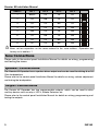
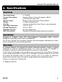
Installation Manual Premier 8X INS163-3 Premier 8X Installation Manual 1. INSTALLATION The Premier 8X Expander is only compatible with the Premier range of control panels. Expanders can be connected serially (daisy chain), in parallel (star) or any combination of the two. Mounting Remove each screw cap by inserting a flat bladed screwdriver into the slot and turning anticlockwise, excessive force is NOT required. Remove both of the cover screws and put them in a safe place along with the screw caps. Gently pull the over away from the base applying slight pressure to the sides at the top of the expander if required. The front cover should now be off. Mount the expander using at least two appropriate countersunk screws (no larger than No. 8). A keyhole slot has been provided to assist mounting and aid leveling. Wiring It is strongly recommended that the system is completely powered down (mains and battery) before wiring the expander. Connect the expander to the control panel using 4-core cable as follows: Expander Control Panel Description + + +12V Supply - - 0V Supply T T Transmit Data R R Receive Data The networks are made up of four terminals incorporating power and data. To ensure correct operation, all four terminals on the device must be connected to the corresponding terminals on the control panel or previous device. Expanders can be connected using 4-core cable. However, it is recommended that 6 or 8core cable is used as the spare cores can be used to ‘Double Up’ on the power connections if needed. Standard 7/0.2 alarm cable can be used for most installations. However, under certain conditions it may be necessary to use screened cable. Selecting an Address Each expander must be assigned a different address using the DIL switches located in the top left of the PCB. The table below shows the expander addressing: INS163 2 Premier 8X Installation Manual Address DIL 1 DIL 2 DIL 3 DIL 4 1 On/Off Off Off Off 2 Off On Off Off 3 Off Off On Off 4 Off Off Off On 5 On Off Off On 6 Off On Off On 7 Off Off On On 8 On Off On On 1 2 3 4 1 2 3 4 1 2 3 4 1 2 3 4 1 2 3 4 1 2 3 4 1 2 3 4 1 2 3 4 Never set two expanders on the same network to the same address. Expanders are factory set to address 1. Zone Connections Please refer to the control panel Installation Manual for details on wiring, programming and testing the zones. Speaker Connections The Premier 8X Expander has a speaker driver output and can be used for driving 8 or 16 Ohm loudspeakers. Please refer to the control panel Installation Manual for details on wiring, volume adjustment and testing the loudspeaker. Output Connections The Premier 8X Expander has two programmable outputs, which can be used to drive auxiliary devices such as relays, LED’s, Smoke Detectors etc. Please refer to the control panel Installation Manual for details on wiring, programming and testing the outputs. 3 INS163 Premier 8X Installation Manual 2. Specifications Electrical Operating Voltage Current Consumption Zones Speaker Output Outputs Data Bus Operating Temperature Storage Temperature Maximum Humidity EMC Environment 9 - 13.9VDC Nominal: 50mA; In alarm with speaker: 180mA 8; EOL Resistor Value: 3K3 Minimum load 4Ω Maximum Current 325mA 2; 100mA switched to 0V 4-wire up to 100m Star, Daisy Chain or any combination -10°C to +45°C -20°C to +60°C 95% non-condensing Residential/Commercial/Light Industrial or Industrial Standards Conforms to European Union (EU) Electro-Magnetic Compatibility (EMC) Directive 89/336/EEC (amended by 92/31/EEC and 93/68/EEC). The CE mark indicates that this product complies with the European requirements for safety, health, environmental and customer protection. Warranty All Texecom products are designed for reliable, trouble-free operation. Quality is carefully monitored by extensive computerised testing. As a result the Premier 8X Expander is covered by a two year warranty against defects in material or workmanship. As the Premier 8X Expander is not a complete alarm system but only a part thereof, Texecom cannot accept responsibility or liability for any damages whatsoever based on a claim that the Premier 8X Expander failed to function correctly. Due to our policy of continuous improvement Texecom reserve the right to change specification without prior notice. Premier is a trademark of Texecom Ltd. © Texecom Ltd 2010 INS163 4 Texecom Ltd Limitations and Disclaimer This system has been carefully designed to be as effective as possible, however not even the most advanced alarm system can guarantee 100% protection. There are circumstances involving fire, burglary, or other types of emergencies where it may not provide protection. Any security product whether commercial or residential may be compromised deliberately or may fail to operate as expected for a variety of reasons. Texecom cannot accept liability for the System failing to perform as expected. Some but not all of the reasons for this may include:Intruders may enter through an unprotected access point, circumvent a sensing device, evade detection by moving through an area of insufficient coverage, disconnect a warning device, or interfere with or prevent the proper operation of the system. Intrusion detectors powered by AC will not operate if AC power is disconnected or inadequate. Any interruption to AC power, however brief, will render that device inoperative while it does not have power. Power interruptions of any length are often accompanied by voltage fluctuations which may damage electronic equipment such as a security system. After a power interruption has occurred, immediately conduct a complete system test to ensure that the system operates as intended. A user may not be able to operate a panic or emergency switch possibly due to permanent or temporary physical disability, inability to reach the device in time, or unfamiliarity with the correct operation. Even if the system responds to the emergency as intended, the occupants may not have enough time to protect themselves from the emergency situation. Where the alarm system is monitored, the authorities may not respond appropriately or in time to protect the occupants or their belongings. In the case of wireless detectors, signals may not reach the receiver under all circumstances which could include metal objects placed on or near the radio path, deliberate jamming or other inadvertent radio signal interference. Motion detectors can only detect motion within the designated areas as shown by the detection pattern in their respective installation instructions. They cannot discriminate between intruders and intended occupants. PIR detectors cannot detect motion which occurs behind walls, ceilings, floor, closed doors, glass partitions, glass doors or windows. If the detector is battery operated, it is possible for the batteries to fail. Even if the batteries have not failed, they must be charged, in good condition and installed correctly. Our wireless detectors have been designed to provide several years of battery life under normal conditions. Ambient conditions such as high humidity, high or low temperatures, or large temperature fluctuations may reduce the expected battery life. While each transmitting device has a low battery monitor which identifies when the batteries need to be replaced, this monitor may fail to operate as expected. Regular testing and maintenance will keep the system in good operating condition. Passive infrared motion detectors operate by sensing changes in temperature. However their effectiveness can be reduced when the ambient temperature rises near or above body temperature or if there are intentional or unintentional sources of heat in or near the detection area. Some of these heat sources could be heaters, radiators, stoves, barbeques, fireplaces, sunlight, steam vents, lighting and so on. Dual technology microwave detectors must be adjusted by the installer so they do not detect motion outside the intended protected area. The protection pattern may also be affected by metal objects or foil covered insulation. Smoke detectors have played a key role in reducing residential fire deaths, however they may not activate or provide early warning for a variety of reasons in as many as 35% of all fires, according to data published by the Federal Emergency Management Agency. Some of the reasons smoke detectors used in conjunction with this System may not work are as follows:• • • • Smoke detectors may have been improperly installed and positioned. Smoke detectors may not sense fires that start where smoke cannot reach the detectors, such as in chimneys, in walls, or roofs, or on the other side of closed doors. Smoke detectors also may not sense a fire on another level of a residence or building. A second floor detector, for example, may not sense a first floor or basement fire. Finally, smoke detectors have sensing limitations. No smoke detector can sense every kind of fire every time. In general, detectors may not always warn about fires caused by carelessness and safety hazards like smoking in bed, violent explosions, escaping gas, improper storage of flammable materials, overloaded electrical circuits, children playing with matches, or arson. Depending on the nature of the fire and/or location of the smoke detectors, the detector, even if it operates as anticipated, may not provide sufficient warning to allow all occupants to escape in time to prevent injury or death. Alarm warning devices such as sirens, bells or horns may not alert people or wake up sleepers if they are located on the other side of closed or partly open doors. If warning devices are located on a different level of the building from the bedrooms, then they are less likely to wake or alert people inside the bedrooms. Even persons who are awake may not hear the warning if the alarm is muffled by noise from a stereo, radio, air conditioner or other appliance, or by passing traffic. Finally, alarm warning devices, however loud, may not warn hearing-impaired people. Telephone lines or other types of communication medium needed to transmit alarm signals from protected premises to a central monitoring station or other response service may be out of service. Telephone lines are also subject to compromise by sophisticated intruders. Any type of tampering whether intentional or unintentional may impair the proper operation of the system. Although every effort has been made to make this expander as reliable as possible. Even the most reliable electrical devices, including this alarm system, may fail to perform correctly due to unexpected failure of a component part. Inadequate maintenance is the most common cause of alarm failure. Therefore, test your system at least once per week to be sure sensors, sirens, and phone communications are all working correctly. Although having an alarm system may make you eligible for reduced insurance premiums, regardless of its capabilities however, the system is no substitute for insurance. Homeowners, renters or other occupiers should continue to insure their lives and property. Note to Installers This warning contains vital information. As the only individual in contact with system users, it is your responsibility to bring each item in this warning to the attention of the users of this system. Notes Notes Texecom Limited, Bradwood Court, St. Crispin Way, Haslingden, Lancashire BB4 4PW, England. Technical Support: UK Customers Tel: 08456 300 600 (Calls charged at local rate from a BT landline. Calls from other networks may vary.) International Customers Tel: +44 1278 686197 Email: [email protected] © Texecom Limited 2010 INS163