1
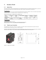
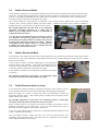
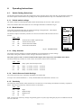
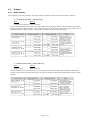
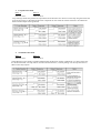
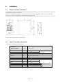
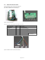
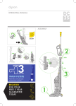
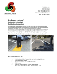
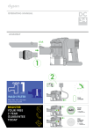
User Manual
1.
Introduction
EzyLoops Systems, Surface mounted Pedestrian Activated Switch Pads are a pressure activated electronic method of
detection that provides both “passive presence detection” and “directional detection” of pedestrians and vehicles.
Used with the Nortech PD134TLC Tactile Loop Controller the system has been designed to provide specific “logic”
outputs from the patented tactile Switch Pad intended primarily for pedestrian detection. The Switch Pad may also
incorporate an inductive loop for vehicle detection.
Due to the combination of vehicle and pedestrian detection capabilities, the tactile loop controller and Switch Pad can
be used in a number of applications in low speed / low volume (car park) traffic and pedestrian control applications as
follows:
a) Vehicle detection – by means of the pressure actuation due to the vehicle wheels on the tactile sensor OR by use of
the optional built in inductive loop OR a combination of both.
b) Pedestrian Detection – by pressure actuation
The controller is capable of providing timing functions (delay) of the pedestrian actuation
c) Movement Direction detection – in analysing the movements over the Switch Pad to determine direction of
movement in both vehicle and pedestrian modes.
2.
Hardware Detail
2.1.
Switch Pad
EzyLoops Systems, Surface mounted Pedestrian Activated Switch Pads are pre-formed and encapsulated in a protective
non-slip tactile surface mat, so that they may be laid onto the surface of a pavement as a single unit
Pad construction:
Heavy-duty, extruded, two-ply vinyl mat, which encapsulates the electronic switches, with a UV resistant, slip resistant,
tactile mat surface. The standard sized mat is 800mm wide by 1400mm long.
Optional sizes through to 1400mm wide by 2400mm long.
Electrical details:
Max Operating Voltage: 24 V DC
Operating Current: Min 50 micro amps to 20 milli amps Max, Resistive.
Feeder cable, Min 3 core x (0.75mm2) multi-strand insulated cable.
2.2.
Tactile Loop Controller
The PD134TLC Tactile Loop Controller is designed to be shelf or DIN rail mounted with the controls and visual
indicators at the front and wiring at the rear of the enclosure.
The power, switch pad connections and relay outputs and inputs are all connected to the 11-pin plug, which is mounted
at the rear of the enclosure. This connector mates with the DIN Rail mount screw terminal base.
Figure 2.1 Tactile Loop Controller
Page 2 of 12
2.3.
Switch Pad interface
The Switch Pad is connected to controller by means of a supplied cable with an
interface at the switch pad end.
Figure 2.2 Tactile Mat Interface
3.
Operating Modes
To accommodate the numerous application requirements, this versatile unit may be configured to operate in one of 4
distinct modes.
These modes are :
3.1.
1.
Tactile Presence mode, with / without delay – (optional Loop)
2.
Vehicle Presence mode – Tactile and Loop
3.
Loop Direction mode
4.
Tactile Direction mode
Tactile Presence Mode – (optional Loop)
In this mode the controller provides two separate “presence” outputs. One of these is dedicated to the tactile switches in
the switch pad that respond to pressure. The second output becomes functional if an optional detection loop coil is
embedded in the switch pad. This detection loop coil (vehicle detector) senses the metal content of a vehicle above the
switch pad.
The tactile output provides a “presence” output while a vehicle wheel or pedestrian is standing on the switch pad. This
output may be immediate when the pressure is applied or delayed by switch settings on the controller. This output is
constant for the duration of the pressure applied to the switch pad.
The delay settings provided are 2 seconds, 4 seconds and 6 seconds.
When this delay is selected, the tactile output only occurs after the
delay period. Therefore there will be no output when pedestrians or
vehicles pass over the sensor and do not remain there for the length
delay period.
When a delay is selected, there is also a default time extension of 4
seconds. This means once the actuation is removed after the delay
period has expired; the output will remain on for a further 4 seconds.
If pressure is reapplied again before the 4 second period has expired,
the output will remain on constantly.
The optional vehicle detector output is immediate when a vehicle is present and is constant for the duration of the
vehicle presence. The vehicle detector output is unaffected by any delay settings.
The intended application for this mode is without the optional vehicle loop and is for “passive pedestrian
detection” at signalised pedestrian crossings.
Page 3 of 12
3.2.
Vehicle Presence Mode
In this mode the switch pad is provided with a detection loop coil that senses the metal content of the vehicle above the
switch pad. The loop detector output of the controller provides a “presence” output while a vehicle is present over the
loop coil. This output is immediate when the vehicle arrives and remains on for the duration of the vehicle presence.
Any timing functions selected to not apply for this output.
The second “pedestrian” output operates as described in the “Tactile Presence Mode” above with the important
exception that a vehicle presence disables the tactile output. Therefore the tactile output positively identifies a
pedestrian presence in the absence of a vehicle over the sensor.
The intended application for this mode is for monitoring
pedestrian and traffic movements on a traffic ramp or
similar area, providing alarms to drivers or pedestrians of
traffic/pedestrian movements.
It is also ideal for the detection of bicycles that are stopped
in a “bike lane” that is directly adjacent to a vehicle lane. In
this situation the tactile provides an output in the presence
of a bicycle but without the presence of a vehicle. A Bicycle
is identified because, with the absence of a vehicle presence
to disable the tactile output, it can be assumed that the
tactile has been activated by a bicycle.
3.3.
Vehicle Directional Mode
In this mode the switch pad is provided with an optional detection loop coil that senses the metal content of the vehicle
above the switch pad. The loop detector output and the tactile sensors are used to determine a vehicle presence and the
direction of the vehicle.
In this mode an output is provided immediately on the appropriate
direction output of the controller. This output is immediate when the
vehicle arrives and remains on for the duration of the vehicle presence.
Any timing functions selected to not apply for this output.
In this mode any actuation of the switch pad by pedestrian movements
are ignored.
The intended application for this mode is for monitoring vehicle
movements where directional information is required.
3.4.
Tactile Direction mode (no loop)
In this mode the controller attempts to analyse the direction of the vehicle or person
traversing the switch pad and to provide an output based on the direction determined.
When the passage of a wheel is sensed, the switch pad immediately activates the
appropriate direction output. Such output remains constant while the pressure of the
wheel remains on the sensor.
The intended application for this mode is for monitoring bicycle or wheel-chair
movements where direction determines the action to be taken.
Where a wheel presence is not detected the controller assumes the actuation is due to
pedestrian movements on the switch pad. In this case the direction may only be
determined when the pedestrian moves off the switch pad.
In this case a brief output pulse is provided on the appropriate direction output once the
sensor is completely de-activated.
Note that further direction outputs may only occur once the switch-pad has been
completely vacated between events. The delay feature is inoperable in the direction
mode regardless of delay switch settings.
Page 4 of 12
4.
Operating Instructions
4.1.
Switch Setting Selections
The faceplate switch settings allow the configuration of the operating mode of the controller, the time delay settings for
the tactile outputs and the inductive loop settings when the optional detection loop coil is imbedded in the sensor.
4.1.1. Default switch settings
All of the 8 switches on the faceplate Mode switch should initially be set to the “OFF” position.
This is the situation where all switches are set to the right hand side as indicated in Fig 4.1.
4.1.2. Mode Selection
One of the 4 operating modes must be selected according to the application. These modes
and their applications are described in Section 3.
The mode of output is selected by switches No.7 and 8 on the front of the enclosure and is as
follows:
SW8
SW7
Off
Off
On
On
Off
On
Off
On
Tactile Presence Mode (optional loop)
Vehicle Presence Mode
Vehicle Directional Mode
Tactile Directional Mode
ON
Fig 4.1. Faceplate Details
4.1.3. Delay Selection
The Tactile Presence Outputs are normally immediate, but can be delayed by switch settings.
Each Delay setting has a default “extend” setting as described in Section 3.1
This delay operates ONLY on the Switch Pad tactile outputs and is inoperative in the DIRECTION Modes.
The delay selected by switches No.5 and 6 on the front of the enclosure and is as follows:
SW6
SW5
Off
Off
On
On
Off
On
Off
On
Delay option off, Extend option off.
Delay = 2 seconds, Extend = 4 seconds
Delay = 4 seconds, Extend = 4 seconds
Delay = 6 seconds, Extend = 4 seconds
4.1.4. Vehicle Detector Switch Settings
The vehicle detection loop is optionally embedded in the Switch Pad.
If a loop is not connected Switches 1 – 4 only should remain off as described in Section 3.2.1.
4.1.5. Sensitivity
The sensitivity of the detector allows the detector to be selective as to the change of inductance necessary to produce a
detect. There are four sensitivity selections and are set as follows: SW4
SW3
Off
On
Off
On
Off
Off
On
On
High
Medium-High
Medium-Low
Low
Med -Low and Low sensitivity settings will generally ignore bi-cycles, high setting may be prone to ambient electrical
noise on some sites.
Page 5 of 12
4.1.6. Frequency
The frequency switches are the lower two switches, numbered 1 and 2. There are four frequency selections and are set
out as follows:
SW2
SW1
Off
Off
High
On
Off
Medium-High
Off
On
Medium-Low
On
On
Low
The frequency switches allows the operating frequency of the loop to be shifted higher or lower depending on the
switch position. The frequency of the loop is determined by the loop size, and the frequency of the switch simply
causes a frequency shift on the loop.
Where more than one detector is used the detectors must be set-up to ensure that there is no cross-talk (interference)
between the detectors. This can be achieved by ensuring that the loops of the two detectors are spaced sufficiently apart
(approximately 2 metres between adjacent edges) and also ensuring that the detectors are set to different frequencies.
As a general rule, the detector connected to the inductive loop with the greatest inductance should be set to operate at
the lowest frequency. Loop inductance increases as loop size, number of turns in the loop and feeder length increases.
4.1.7. Reset Switch
The detector automatically tunes to the inductive loops connected to it when power is applied, whether on initial
installation or after any break in the power supply. Should it be necessary to retune the detector, as may be required
after the changing of any switch selections, momentary operation of the RESET switch will initiate the automatic tuning
cycle.
On power up the controller checks all tactiles in the Switch Pad and excludes any faulty lines.
The reset switch does not initiate a re-check of the Switch Pad; recycle the power to achieve this.
4.2.
Front Panel Indicators
4.2.1. Power Indicator
The Power (Red) LED will glow permanently to indicate that the unit is functional. The red LED also serves as an
optical interface to the DU100 Diagnostic Unit.
4.2.2. Status Indicator
The STATUS (green) LED will normally be off once the unit is functional.
The green LED will also glow whenever a vehicle is detected passing over the inductive loop or due to pressure applied
on the tactile mat.
The green LED will also indicate the vehicle loop tuning and fault conditions as follows:
1.
Detector Tuning
While the detector is tuning the presence LED (Green) will be on. It will extinguish when the system is tuned. The
green LED will flash at a rate of 1 Hz after tuning. This is used to indicate the frequency of the loop to the user. Every
flash of the LED is equivalent to 10 kHz. It will stop when the operating frequency is reached. This operation is also
performed whenever the reset button is depressed.
2.
Loop Sensor Faults
If a fault occurs with the loop, the green LED will come on and flash off at the rate of 2Hz indicating the fault. If the
fault is self-healing the detector will recommence operation. However the LED will remain on, but will go off for brief
intervals in periods of undetect indicating that a fault has occurred. This “fault memory” condition can be restored by
removing the power or by depressing the reset button.
Page 6 of 12
4.3.
Outputs
4.3.1. Relay Outputs
The controller provides two normally open relay contacts to indicate presence and direction outputs as follows:
1.
Tactile Presence mode – (optional Loop)
Relay 1
Relay 2
Loop Presence (optional) Tactile Presence
Presence Mode means that any detect on the loop will generate an output on Relay l, whereas a detect on the tactile
mat will generate an output on Relay2. The output will persist for the duration of the presence of the vehicle and / or
pedestrian (subject to delay settings). With no loop in use there will be no outputs on Relay 1
2.
Vehicle Presence mode – Tactile and Loop
Relay 1
Relay 2
Loop Presence
Tactile Presence
Presence Mode means that any detect on the loop will generate an output on Relay l for the duration of the detect,
whereas a detect on the tactile mat will generate an output on Relay2 for the duration of that detect (subject to delay
settings)
Page 7 of 12
3.
Loop Direction mode
Relay 1
Relay 2
Direction A-B
Direction B-A
Loop AB Logic mode will generate an output based on the direction of a vehicle over the loop using the tactile mat
as the second "loop" to determine the direction. Important to note is that the vehicle will have to be undetected
before another output will be generated.
4.
Tactile Direction mode
Relay 1
Relay 2
Direction A-B
Direction B-A
Tactile Direction Logic mode is capable of determining the direction of either a pedestrian or a vehicle using only
the Tactile Mat itself. The loop state is not taken into account here; a vehicle passing over the loop will have no
effect on the relay outputs.
Page 8 of 12
5.
Installation
5.1.
Tactile Controller installation
The PD134TLC detector is designed to be shelf or DIN rail mounted with the controls and visual indicators at the front
and wiring at the rear of the enclosure.
The power, loop and relay outputs are all connected to the single 11-pin plug, which is mounted at the rear of the
enclosure. The screw terminal base is used for connections to the unit.
Also the unit interfaces to tactile mat via the Tactile Mat Interface, the 301 FT0218, which connects via the 11-pin plug.
32
Figure 5.1 PD134TLC Controller Housing detail.
5.2.
Tactile Controller wiring detail
11-Pin connector wiring for the PD134TLC
301FT0041
WIRING HARNESS
WIRE COLOUR
PIN #
FUNCTION
Red
1
Power Supply
Black
2
Power Supply
Grey
3
N/O Relay 2 Contact
Violet
Yellow
4
5
Common Relay 2 Contact
N/O Relay 1 Contact
(2 Amp and 240V ac max)
Brown
6
Common Relay 1 Contact
White/Blue
7
Loop
Blue
White/Brown/Green
8
9
Loop
Tactile Mat Ground
Orange/Brown
10
Tactile Mat Power
Green
11
Tactile Mat Communication
Page 9 of 12
12-24V AC-DC 45-65Hz
0.2A Max
(2 Amp and 240V ac max)
Twist this pair
Connect switch pad
interface here, see Fig
5.3
5.3.
Switch Pad Interface detail
Switch Pad interface cable connection to the PD134TLC
Part number 301ND0220 (to be used without loop)
Part number 301ND0221 (to be used with loop)
Figure 5.2 Switch Pad Interface
Connector wiring for the PD134TMI - Part number 301 FT 0218
8core Cat 5 cable
White/Brown
Brown
White/Orange
Orange
White/Green
Green
White/Blue
Blue
PIN #
1
2
3
4
5
6
7
8
FUNCTION
Tactile Mat Ground
Tactile Mat Power Supply
Tactile Mat Ground
Tactile Mat Power Supply
Tactile Mat Ground
Tactile Mat Communication
Loop
Twist this pair
Loop
Figure 5.3 Cable to connect to the PD134TLC detector
Page 10 of 12
5.4.
Switch Pad Installation
5.4.1. Pedestrian Crossing application
Pedestrian actuated signal devices are part of many traffic signals and require the user to push a button in order to
activate a walk signal indicator and initiate a WALK interval. Use of pushbuttons may also lengthen a WALK interval
to provide adequate crossing time. Without a supplemental “passive” pedestrian detection device, there is no guarantee
that the signals will activate or lengthen a walk interval when necessary.
The Pedestrian Activated Detection Pads are designed to be placed in situations where pedestrian interaction with a
pushbutton is known to be periodic or where there are high volumes of disabled pedestrians that may find it difficult to
locate and/or reach the button to initiate or lengthen a walk interval.
Installation of the surface mounted pedestrian pad is by way of a single part adhesive (Seka Flex 521 UV).
Once the location of the pad has been determined, mark-out around the pad with masking tape. A small rebate need to
be cut out of the area that the feeder cable exits the underside of the pad, this is to reduce the chances of the lead wire
being damaged by being “pinched” if a car drives over the pad. Then cut a chann el 10mm deep and 5mm wide, from
the point that the lead wire exits the pad to the nearest PJ Box. Then drill a hole down into the box. Apply the adhesive
to the underside of the pad and place it in position, being sure to have the lead wire exit point over the rebate.
If the surface that the pad is being install on, is asphalt, then the pad can be order with a “Butyl” adhesive already
applied to the underside of the pad. If this is the case, the surface should be primed with a butyl adhesive primer or
similar, then simply peel off the backing paper and stick the pad down.
Once the pad is installed, place a number of small sand bags on the pad to hole it down while the adhesive cures. This
will take approximately 15 min. Seal the lead wire channel and then finish connection in the junction box.
Page 11 of 12
5.4.2. Bicycle Detection Application
The Bicycle Switch Pad (BSP) is only 5mm thick and constructed of heavy duty non-corrosive materials with a non -slip
surface. The switch pad is simply adhered to the surface of an existing bike lane or path approaching a road crossing or
intersection.
This patented Bicycle Switch Pad (BSP-1200) has been designed to be an alternative to a call button as well as being
able to cancel a call if vacated.
Each button or rows of buttons on the switch pad can be individually activated so that both presence and direction can
be determined.
The installation of the Bicycle pad is the same as with the pedestrian pad, described on Page 11.
And as with the pedestrian pad, if the surface that the pad is being installed on, is asphalt, then the pad can be ordered
with a “Butyl” adhesive already applied to the underside of the pad. If this is the case the surface should be primed with
a butyl adhesive primer or similar, then simply peel off the backing paper and stick the pad down.
The Civic Group
Unit 74, Block 503
Greenogue Business Park, Rathcoole,
Co. Dublin
Tel: +353 1 4019914
Fax:+353-1-4019140
Email: [email protected]
Web: www.civic.ie