1
!"#$
$ !
" !
# !! ! !"!
AXIOM is a trademark of AXIOM Technology Co., Ltd.
Award is a trademark of Award Software, Inc.
IBM, PC/AT, PS/2, VGA are trademarks of International
Business Machines Corporation.
Realtek RTL-8139C is a registered trademark of Realtek
Semiconductor Corporation.
Other brand names and trademarks are the properties
and registered brands of their respective owners.
!
2.3.1
2.3.2
2.3.3
2.3.4
2.3.5
2.3.6
"
Watchdog Function Setting: JP1 ............................. 7
Serial Ports Settings: JP9, JP10, JP11 ........................ 8
CMOS Clear Jumper: JP8 ......................................... 8
Flat Panel Connector Voltage Selection: JP2 ........ 8
Compact Flash IDE Mode Selection: JP5 ................ 8
Serial Ports +5V and +12V Power Selection: JP13,
JP15, JP14, JP16 ...................................................... 9
# $
"
!
-
/
$
% #& '( %)% ' # %'*(+) )+, "
'
.'# #,01&2 %' 3.10.1 Flat Panel/CRT Interface Controller ...................... 16
3.10.2 VGA/Flat Panel Connectors .................................. 17
3.10.3 Flat Panel Connector Pin Description ................... 18
%
0# /
'*( $
3.12.1 Digital I/O Software Programming ........................ 21
' " ' Table of Contents
!
-
/
$
"
&# "
34#0#)(3+) "
5%6*) # "
.,# '
+# 7' # #*$"# 8.
# -
78.
# -
73# -
+ # -
" ' /
4.1.1 Chipset ...................................................................... 29
4.1.2 Display memory ........................................................ 29
"'9+: $
4.2.1 Installation for National MediaGX Certified drivers for
Windows 95/98.......................................................... 30
4.2.2 Display drivers ........................................................... 30
' : !
"#$ %; 6.1.1 System configuration verification............................ 33
+7'( 6.2.1 Entering setup ...........................................................
6.2.2 Standard CMOS setup .............................................
6.2.3 BIOS features setup ..................................................
6.2.4 Chipset features setup .............................................
6.2.5 Power management setup ......................................
6.2.6 PnP/PCI configuration..............................................
6.2.7 Integrated peripherals .............................................
6.2.8 Load BIOS defaults ...................................................
6.2.9 LOAD SETUP DEFAULTS ..............................................
6.2.10 Change password ..................................................
iv
34
35
36
37
38
39
40
42
43
43
Table of Contents
6.2.11 Auto detect hard disk ............................................ 44
6.2.12 Save & exit setup .................................................... 45
6.2.13 Exit without saving .................................................. 45
% &'() *
Table of Contents
vi
This page does not contain any information.
Table of Contents
SBC84500 User’s Manual
%% & $ '
!"#$#%&&##'(''')
&''&%&*+,-,./$0#'!-%1
)'$'2'03''4!%5%
#
0&''%6$'02&'0&0
5'''%#''0#'&&#'47
8 7-9,'&!#)$4!%5%$%!%&'
#'%##%'
,
0#%''-&''
&##'''6##52'&:0%$/;$
%#
0 ,#%6'6#2&''&2'2%
-%#%'6'0
'*
,00;'
&0#2&'<&2'#%6
0#%66#2002'-%# 6&6'%
&'$'
=+ '&'&
SBC84500 User’s Manual
%( ' )
Process:
233MHz National Semiconductor Geode
GX1 (other frequency processors are
manufacturer optional)
Chipset:
NS GX1 + CS5530A
Memory:
1x144-pin SODIMM Max. 128MB SDRAM
On-board IDE:
PIO Mode 0-4, DMA Mode 0-1 and One
Channel up to 2 Devices (44-pin
Box-header)
Enhanced IDE ATAPI/16.6/33,LS-120
Bootable
On-Board Multi I/O: One Floppy Port(Box-header) Supports
up to 2 Device (LS-120 Bootable)
One SPP/EPP/ECP Parallel
Port(Box-header),(LS-120 Bootable)
Four 16550 UARTs Compatible Serial
Ports with +5V/+12V Power Output in
Pin 1(+5V) and Pin 9(+12V) via Jumper
Setting:
1 x RS-232 (COM1 as D-type)
1 x RS-232/422/485 Jumper Selectable
(COM2 Box-header)
2 x RS-232 (COM3/4 Box-header)
One IrDA (Pin-header) for Wireless
Communication
PS/2 KB /MOUSE:
PS/2 Type (Mini-Din Connector)
Watchdog Timer:
System Reset Software Programmable
Timer Interval
64 Levels, 0.5~8 / 5~80 / 50~800 /
100~1600 Seconds
SBC84500 User’s Manual
BIOS:
AWARD BIOS with DMI, Plug-and-Play
& Y2K Compliant in 2Mbit Flash Rom
SmartView VGA BIOS Function
Integration Ethernet Novell Boot Rom
Function
RTC:
Integration in W83977AF with external
Lithium Battery
On-Board Display:
CS5530A South Bridge Integrated
Support CRT/TFT Display via UMA Max.
to 4MB Sharing Memory
Resolution ~Non-interlaced CRT and
TFT Monitor up to 1024 x 768 @ 64K
Color
On-Board Ethernet:
Realtek 8139C PCI PnP 10/100Base-T
Ethernet
On-Board Audio:
AC97 Codec with Surround Sound
Microsoft Direct Sound 3D Audio
Supported
32-bit Sound Blaster TM and Sound
Blaster TM Pro Compatible
Full-duplex Operation for Simultaneous
Record and Playback
Internal MIC-in, Line-in and
Speaker-out interface Reserved
On-Board SSD:
CompactFlash$ Socket
Extension:
One 16-bit PC/104 Connector
Other Feature:
Single +5V
Internal Power Connector
(+5V,GND,GND,+12V)
SBC84500 User’s Manual
This page does not contain any information.
SBC84500 User’s Manual
(% *+$ SBC84500 User’s Manual
(( ,$ SBC84500 User’s Manual
( -#' +
,
*(2&'0''6&##%'6
##>&0#''2,%%2'%''>&0#''2
'5
Jumper
JP1
JP2
JP5
JP8
JP9
JP10
JP11
JP13, JP15
JP14, JP16
Default Setting
Jumper Setting
Watchdog Trigger Disabled
Flat Panel Connector Voltage Selection:
Flat Panel Signal Level at 5.0V
Compact Flash IDE Mode for
Master/Slave Selector Setting: Slave
Clear CMOS Jumper: Normal
COM2 RS232/422/485 Settings: RS-232
COM2 RS232/422/485 Settings: RS-232
COM2 RS232/422/485 Settings: RS-232
Open
Short
Short
Short
Short
Serial Port with +5V/+12V Power Setting
Short (3-5,4-6)
Short 1-2
Open
1-2
1-2
3-5, 4-6
3-5, 4-6
,'2'0#%'&'
*('
'5''&'#'&'3'=?
#20'%'$''22'''=? Watchdog Function
Reset system when Watchdog triggered
Disabled
Settings
Short 2-3
Open (default)
SBC84500 User’s Manual
,
*(#5%#'$@A
!"" @
A
!""+""+,#2>&0#''2'
%%2'%
"'''A
!""+$'%%2>&0#5''
'%6
Options
RS-232 (default)
RS-422
RS-485
Settings
JP9
JP10
JP11
Short 1-2
Short 3-4
Short 5-6, 7-8
Short 3-5, 4-6
Short 1-3, 2-4
Short 1-3, 2-4
Short 3-5, 4-6
Short 1-3, 2-4
Short 1-3, 2-4
!"
Options
Clear CMOS
Normal
Settings
Short 2-3
Short 1-2 (default)
# $
*(&##'B*B*%'#%'$'5%'2
%'0#%'6''2:
V DDM of LCD1 connector
5 V
3.3 V
JP2
Short 1-2 (default)
Short 2-3
% !
&'(%
*(0#'-%/('+
%5%'
0#%'6''2:
CF IDE Mode
Master
Slave
JP5
Short
Open (default)
SBC84500 User’s Manual
) *%$*$+
%#)
,&#'5B*+B "*##%'6= 8B*9
=8B "*9=C8B "*9$#2'>&0#%',
A
!""D#20'%' JP13, JP15, JP14, JP16 COM1 COM2 COM3 COM4
Description
Short 3-5 (default) Pin 1 Pin 1 Pin 1 Pin 1
Data Carrier Detect (DCD)
Short 4-6 (default) Pin 9 Pin 8
Ring Indicator (RI)
Pin8 Pin 8
Short 1-3 (5V)
Pin 1 Pin 1 Pin 1 Pin 1
Power for 5V
Short 2-4 (12V)
Pin 9 Pin 8 Pin 8 Pin 8
Power for 12V
SBC84500 User’s Manual
(. ,'%)'
*('@'%5&
)$%##6)#',%%2'%%''&'
''
*(#2#20'
#'
Connector
J1
U25
LCD1
IDE1
CON1
JP6
FDD1
LAN1
KBMS1
COM1
COM2
COM3
COM4
VGA1
USB1,USB2
J2
CN1
PC104-1
PC104-2
SOMIMM1
JP7
JP4
JP3
Description
IrDA Connector
CompactFlash Socket
Flat Panel Connector
IDE Connector
Parallel Port
Power LED
FDC Connector
Ethernet Connector (1 st )
K/B and PS/2 Connector
COM1
COM2
COM3
COM4
CRT Connector
USB Connector
Main Power Connector (+5V,+12V)
8 Bit Digital I/O Connector
PC/104 Connector
PC/104 Connector
SODIMM Socket
HDD LED
Hardware Reset
Audio Connector
SBC84500 User’s Manual
% ) /,
#
/''#0'
*(6&'%%'
/'0)6'%'#&'&
&2#&%&6'50#''%'
0#''5''''%'2,$
'&2'
*('%$%62&6&%')#
06''2?2&2''##%%%%'
0#'6''!%5 ( ,
,
*(&##'@ !"E;=?
6'0
'=?#'&.&@$3,$3C$C
!/
50'5$''%%=?'0
6'0D#0
,6'0
&
*(=%&2=%6
,
*('2%"-%(=A&##'
#!0''6'0
SBC84500 User’s Manual
. / " /
*( !#
/)'$%'&##'
4$"$4$ "
/0&%$#52'&'
&#' "6'0006 #'
$$ ,
*(&%%6=0#'%'%'' 4
'&#'F&'%' 4'
=,
0##2%'' 4'&#'F&'%%G
NMI
Parity check error
IRQ0
System timer output
Keyboard
Interrupt rerouting from IRQ8 through IRQ15
Serial port #2
Serial port #1
Audio port
Floppy disk controller
Parallel port #1
Real time clock
Reserved
Serial port #3
Serial port #4
PS/2 mouse
Math co-processor
Primary IDE channel
Reserved
IRQ1
IRQ2
IRQ3
IRQ4
IRQ5
IRQ6
IRQ7
IRQ8
IRQ9
IRQ10
IRQ11
IRQ12
IRQ13
IRQ14
IRQ15
SBC84500 User’s Manual
0 / "'
I/O
000-01F
020-021
022-023
040-05F
060-06F
070-07F
080-0BF
0A0-0BF
0C0-0DF
0F0-0FF
170-1FF
220-22F
2E8-2EF
2F8-2FF
378-37F
3B0-3DF
3E8-3EF
3F0-3F7
3F8-3FF
Address Map Description
DMA Controller #1
Interrupt Controller # 1, Master
Chipset address
System Timer
Standard 101/102 keyboard Controller
Real time Clock, NMI Controller
DMA Page Register
Interrupt Controller # 2
DMA Controller # 2
Math Coprocessor
VIR BUS Master PCI IDE Controller
Audio 16bit sound
Serial Port 4
Serial Port 2
Parallel Printer Port 1
Cyrix Graphic Adapter
Serial Port 3
Floppy Disk Controller
Serial Port 1
!"
!"
#$#
%& ' ()!*+
,#-."' ()!*+
SBC84500 User’s Manual
1 " $+ Channel
0
1
2
3
4
5
6
7
Function
Available
Available
Floppy disk (8-bit transfer)
Parallel**
Cascade for DMA controller 1
Available
Available
Available
SBC84500 User’s Manual
2 ) ,
*(&% %$%'&##'"/(5$=
&/('%%&##'0'+%50#'
'''00'4!6'&$0''
''
IDE1: IDE Connector Pin Assignment
Pin
1
3
5
7
9
11
13
15
17
19
21
23
25
27
29
31
33
35
37
39
41
43
Description
Reset #
Data 7
Data 6
Data 5
Data 4
Data 3
Data 2
Data 1
Data 0
GND
INPACK
IOW #
IOR #
IOCHRDY
DACK
Interrupt IRQ14
SA1
SA0
HDC CS0 #
HDD Active #
+5V
GND
Pin
2
4
6
8
10
12
14
16
18
20
22
24
26
28
30
32
34
36
38
40
42
44
Description
GND
Data 8
Data 9
Data 10
Data 11
Data 12
Data 13
Data 14
Data 15
No connector
GND
GND
GND
GND
GND
WP
PDIAG
SA2
HDC CSI #
No connector
+5V
No connector
SBC84500 User’s Manual
3 '$45 6(7
,
*(
F&##'0#'-%))'
'%'&##''/('0#'-%),
)''%#%%62'#5'6''%%''
0#'-%)
3'%%2052'0#'-%)$#%0)&
'''6'0#
,0#'-%)&%'':/:)56&
=6'0
%8 '$/ ) ,-.&/
,
*(&%
$2!#0%'#%+&#
*#%6'%%' H6''#%'5
A,#%66%'#%#%6
Chipset:
NS CX5530A
Display memory:
1 ~ 4 MB share memory, set in
BIOS
Display type:
Supports CRT and TFT LCD
displays. Can display CRT and
flat panel simultaneously
Flat panel display mode:
Panel resolution supports up to
1024 x 768 @ 18 bpp. Supports
18-bit TFT LCD panel
CRT display mode:
Non-interlaced CRT monitors
resolutions up to 1280 x 1024
@ 256 colors or 1024 x 768 @
16 bpp
SBC84500 User’s Manual
$01,
,
*('''&##''A,*%'
#%#%6$#'5%60&%'&%6' !#
'00%6&'A,*#%6$
!#$
&%!!%%'#%'2&''*
'5''&'%'6>&0#''2F&
,%%2''%'#20''A,+*
''%'#%'$#'5%6
VGA1: CRT/VGA Connector Pin Assignment
Pin
Description
Pin
Description
1
Red
2
Green
3
Blue
4
N/A
5
GND
6
GND
7
GND
8
GND
9
DCC VCC
10
GNS
11
No connector
12
DCC Serial Data
13
Horizontal Sync
14
Vertical Sync
15
DCC Serial Clock
16
No connector
LCD1: Flat Panel Connector Pin Assignment
Pin
Description
Pin
Description
1
No connector
2
+12VM
3
GND
4
GND
5
VDDM
6
VDDM
7
No connector
8
GND
9
No connector
10
No connector
11
B0 (P2)
12
B1 (P3)
13
B2 (P4)
14
B3 (P5)
15
B4 (P6)
16
B5 (P7)
17
No connector
18
No connector
19
G0 (P10)
20
G1 (P11)
21
G2 (P12)
22
G3 (P13)
Continued . . . . .
SBC84500 User’s Manual
Pin
Description
Pin
Description
23
G4 (P14)
24
G5 (P15)
25
No connector
26
No connector
27
R0 (P18)
28
R1 (P19)
29
R2 (P20)
30
R3 (P21)
31
R4 (P22)
32
R5 (P23)
33
GND
34
GND
35
FPCLK
36
FPVSYNC (FLM)
37
FPDISP
38
FPHSYNC (LP)
39
GND
40
FPENABKL
41
GND
42
No connector
43
No connector
44
VDDM
'!
Name
P0~P23
FPENABKL
Flat Panel Backlight Enable Output
FPCLK
Flat Panel Clock
FPDISP
Flat Panel Display Enable Output
FPVSYNC
FPHSYNC
Description
Flat panel data output
Flat Panel Vertical Sync Output
Flat Panel Horizontal Sync Output
+12VM
Controlled +12V power
VDDM
Controlled 3.3V or 5V power selected by JP2
SBC84500 User’s Manual
%% $''/5
$$ ,
*(#5!#'6#'$
&##'2&#''%##65,%##65&%6'
%%2'6#:+ +" FDD1: Floppy Disk Connector Pin Assignment
Pin
Pin
Description
1
GND
Description
2
Reduce write current
3
GND
4
5
GND
6
No connector
Density select
7
GND
8
Index #
9
GND
10
Motor enable A #
11
GND
12
Drive select B #
13
GND
14
Drive select A #
15
GND
16
Motor enable B #
17
GND
18
Direction #
19
GND
20
STEP #
21
GND
22
Write data #
23
GND
24
Write gate #
25
GND
26
Track 0 #
27
GND
28
Write protect #
29
NC
30
Read data #
31
GND
32
Head select #
33
NC
34
Disk change #
SBC84500 User’s Manual
%( +$
!"
# !"$
%
CN1: Digital I/O Connector
Pin
1
3
5
7
9
11
13
15
17
19
Signal
DIO Out 0
DIO Out 1
DIO Out 2
DIO Out 3
DIO Out 4
DIO Out 5
DIO Out 6
DIO Out 7
GND
NC
Pin
2
4
6
8
10
12
14
16
18
20
Signal
DIO In 0
DIO In 1
DIO In 2
DIO In 3
DIO In 4
DIO In 5
DIO In 6
DIO In 7
GND
NC
SBC84500 User’s Manual
'&,/+
&
Output Address Bit
Output Address Bit
Out-0
123h
0
In-0
123h
0
Out-1
123h
1
In-1
123h
1
Out-2
123h
2
In-2
123h
2
Out-3
123h
3
In-3
123h
3
Out-4
123h
4
In-4
123h
4
Out-5
123h
5
In-5
123h
5
Out-6
123h
6
In-6
123h
6
Out-7
123h
7
In-7
123h
7
Example program;
Out 123h, 03h
Out-0, Out-1
Turn On
Out-2, Out-3
Turn Off
Out 123h, 0Ah
Out-0, Out-2
Turn Off
Out-1, Out-3
Turn On
Example program;
If INPUT 123 is
(1011), then INPUT-2 is “0”
If INPUT 123 is (1100), then INPUT-0 & 1 are “0”
** The INPUT signal has to be TTL signal
SBC84500 User’s Manual
% ,
$$ $,
) ,=A,
*(0&%'!0#%%%#'%'
&##':
!"
%&"&"&'"( !
) !"
* +*&&,
!*&&
-.*&&-/+***-(01
,
!"
2!&3
+*&,***-(01
,%''#%%%#'.=, 8IE9$.=,"
8"IE9$.=,8E9%6
'&#
CON1: Parallel Port Connector Pin Assignment
Pin
Description
Pin
Description
1
Strobe #
2
Auto Form Feed #
3
Data 0
4
Error #
5
Data 1
6
Initialize #
7
Data 2
8
Printer Select In #
9
Data 3
10
GND
11
Data 4
12
GND
13
Data 5
14
GND
15
Data 6
16
GND
17
Data 7
18
GND
19
Acknowledge #
20
GND
21
Busy
22
GND
23
Paper Empty #
24
GND
25
Printer Select
26
GND
SBC84500 User’s Manual
%. $,
) ,
*(&%#'$'
$$A
!"""A
!""+""+$'
%'5>&0#''2'#'5B*+ "*## 8B*9
#C8B "*9$#2>&0#%',A
!""D#
20'%'%G
CON1 COM2 COM3 COM4
1
6
2
7
3
8
4
9
5
X
1
2
3
4
5
6
7
8
9
10
NOTE:
1
2
3
4
5
6
7
8
9
10
1
2
3
4
5
6
7
8
9
10
Description
Data Carrier Detect (DCD)
Data Set Ready (DSR)
Receive Data (RXD)
Request to Send (RTS)
Transmit Data (TXD)
Clear to Send (CTS)
Data Terminal Ready (DTR)
Ring Indicator (RI)
Ground (GND)
GND
The COM2~COM4 ports of SBC84500VEA are pin header
type connectors and COM1 is a DB-9 connector.
The RS-422/485 pin assignment for COM2 is listed as follows;
Pin
1
2
3
4
5
6
7
8
9
10
RS-422
TXDx
TXD+
x
RXD+
x
RXDx
GND
x
RS-485
DATAX
DATA+
X
X
X
X
X
GND
X
SBC84500 User’s Manual
% "'
"'
%
"'(
"' "'(
)
"'
Pin #
1
2
3
4
Signal Name
USB0/1 Vcc
USB0/1USB0/1+
USB0/1 GND
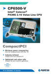
%0 $ $5""
,
*(' 4 0#'%A%,0%)
8A,9 "6'
A'3/3CII-$'
F&5%',
A''6'02&'0'
'5'
(,?=#20,A,'
A)#'
'56''6'6'0#'&$'''6
#%''6 %1 9 /:
,("# /'=
+")6'
KBMS1
SBC84500 User’s Manual
%2 ,AJ!'89&('',''
*('&$>&'#%&2'%''
''''%'&
LAN1 : RJ-45 Connector Pin Assignment
Pin
1
2
3
6
other
G
O
Signal
Tx+ (Data transmission positive)
Tx- (Data transmission negative)
Rx+(Data reception positive)
Rx- (Data reception negative)
Not use
Green LED, light when 100M link
Orange LED,flash when active
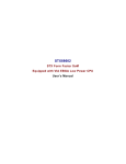
%3 !#/'%00&'
J1
(8 , '# 'B*+B "*##&'''
*(,
*(B*0%#'
Pin
1
2
3
4
Description
+12V
GND
GND
+5V
SBC84500 User’s Manual
(% ,%8. ,=+ &'%''0#'0''
04K@K&%%60#'%''
&,
=+ '%'#''!%=+ 0&%$&
&0&%$@000&%0&%'!+0&%L'
PC104-1: PC/104 Bus Pin Assignment
PIN No.
1
3
5
7
9
11
13
15
17
19
21
23
25
27
29
31
33
35
37
39
41
43
45
47
PIN Name
IOCHCHK *
SD7
SD6
SD5
SD4
SD3
SD2
SD1
SD0
IOCHRDY
AEN
SA19
SA18
SA17
SA16
SA15
SA14
SA13
SA12
SA11
SA10
SA9
SA8
SA7
PIN No.
2
4
6
8
10
12
14
16
18
20
22
24
26
28
30
32
34
36
38
40
42
44
46
48
PIN Name
GND
RESETDRV
+5V
IRQ9
NC
DRQ2
NC
ZEROWS*
+12V
GND
SMEMW *
SMEMR *
IOW *
IOR *
DACK3 *
DRQ3
DACK1 *
DRQ1
REFRESH *
SYSCLK
IRQ7
IRQ6
IRQ5
IRQ4
*
SBC84500 User’s Manual
PIN No.
49
51
53
55
57
59
61
63
PIN Name
PIN No.
SA6
SA5
SA4
SA3
SA2
SA1
SA0
GND
50
52
54
56
58
60
62
64
PIN Name
IRQ3
DACK2 *
TC
SALE
+5V
OSC
GND
GND
PC104-2: PC/104 Bus Pin Assignments
PIN No.
1
3
5
7
9
11
13
15
17
19
21
23
25
27
29
31
33
35
37
39
PIN Name
PIN No.
GND
MEMCS16 *
IOCS16 *
IRQ10
IRQ11
IRQ12
IRQ15
IRQ14
DACK0 *
DRQ0
DACK5 *
DRQ5
DACK6 *
DRQ6
DACK7 *
DRQ7
+5V
MASTER *
GND
GND
2
4
6
8
10
12
14
16
18
20
22
24
26
28
30
32
34
36
38
40
PIN Name
GND
SBHE *
LA23
LA22
LA21
LA20
LA19
LA18
LA17
MEMR *
MEMW *
SD8
SD9
SD10
SD11
SD12
SD13
SD14
SD15
NC
SBC84500 User’s Manual
(( ; JP7: 2 Pin connector for HDD LED communication.
Pin
1
2
Description
LED+
LED-
( , ; JP6: 2 Pin connector for Power LED communication.
Pin
1
2
Description
LED+
LED-
(. JP4: 2 Pin connector for Hardware Reset communication.
Pin
1
2
Description
Signal
GND
( # JP3: 10 Pin connector for Audio communication.
Pin
1
3
5
7
9
2,4,6,8,10
Description
Mic Signal
Left Line Input Signal
Right Line Input Signal
Left Audio Output Signal
Right Audio Output Signal
GND
SBC84500 User’s Manual
! "
.% #
,
*(
!./+*',
#''&%%:
#
!
,
*(&
#''
*'%% '&##'06##&% !'./#%65'%%2A,
0',*
&##'./'$'%&##'
'%!'%%20'8%00*9
2!%&'0%0'20#%'*
0#'%'6
#'!2 2
3' H006$'*'%%5A,#%6
%#%#%6'%&'&#' "@I4'4M%,
#%6006@#'
'&!%%&'
"@I4
"*
SBC84500 User’s Manual
.($$)<&
= 0#%''%%2'#''%%'
*5-%%'
#&'%'''##%6''#'26'0''6&
&2'6&
Important: The following windows illustrations are examples only. You
must follow the flow chart instructions and pay attention to
the instructions which then appear on your screen.
' : ,/!A52'/:'&2&''#'
'": N('O0#2'P('K)6')6
': 36&&2A,#%6$#%0)&''6&%'
#%%&'''28'
'	'06&
*%&'''2839'6&#%606
5'2%6
#&/304/
5/+%," '')''/!A5
%'
'''A&
,6#''#''58%)'@0#%%9
/:Q
Q3CQ
%)M
#'!25
/0)12343
+565$"27
/
/$8/5$8/"*/
"*
SBC84500 User’s Manual
#
% #
,
*(F&##'2#0=%&2=%6
('''&%%60#%'''((("'$
'2AJ!'
( #
#"10Mb/s and 100Mb/s operations
#"Supports 10Mb/s and 100Mb/s N-Way auto
negotiation
#"Full duplex capability
#"Full compliance with PCI Revision 2.1
#"PCI Bus Master data transfers
= #''
&%'##&%'5$'
*((''
'%%2'%@%'6')'%%0>')2#'2
6'0%&25%%'35"@$5@$5@$'.2$
3 $3,$3C$.
5$
?'/$/
=)'50#%'#'26'0
9
SBC84500 User’s Manual
This page does not contain any information.
9
SBC84500 User’s Manual
$
%
&'!
,#'''''25%%'
''
0''
*(=?%'
'&'''&#'
2&'
0% / $>
,&''''%;'&'
&'&2'''$6&%%''#
02','):'%
!'%,6'0&&%%6'&''&#F&'
!'%!'%02&&%%6##'%2
''%%2'&':
#N- O'A(
?(
3''02#'- )6''&''&#
F&
)2 /5/
,&')'&'6'02&'2''5%&
''D
006'6'0'$'#20
&'#&'02<&%%''&'
'&##20
'''2&'0'006 ,''&'
6&%%'2'
''2:
<&''26&6'0'''0
"<&52''''6&6'0
,
006%'#'2&'0'
,
R
006'2%%'&0''6
)&#,''6)&#&%%''60%5$&'
'%%6&$6&%%'#%'0#%'&'
0( #'
D
A&%'!
'&##20''%%&'
06'6'02&','6#0''
''6!)
A'''''
'�''
#'&
3:&;-"*
SBC84500 User’s Manual
)(!
='0#&'#N/%O00'%6,%%%%6&'
'
'&# ↑↓→← ! "
#$%& ' (
)*+,- *%./ 0!01
3 :&; -"*
SBC84500 User’s Manual
)!
,
'
'&#&6'02&'
,0&'/'+,0''2-%##6+E/)/5
''2=%'%%2''&#
% )""2233,*4 %3 -5 -$$#
" )**"",#6-57
1& 1& 1& 89 :
$ ) $;,
$
$
$
$
$
$ ) $;,
$
$
$
$
$
#955469<.
1& 2 0
%!
.
0. !!4= 3;0%12
# !(
$ % & ' ! "
)*+,- *%./ 0!01
>?02+3
#" To set the Date: for example, press either the arrow or
<Enter> button on your keyboard to select one of the fields
(Month, Date or Year) then <#-=<#=
"
''"/ '8 /
#" For IDE hard disk drive setup: please check the following
possible setup procedure:
1. Use the Auto setting for detection during boot-up.
2. Use the IDE HDD AUTO DETECTION in the main menu;
the computer will automatically detect the HDD
specifications.
3. Manually enter the specifications by yourself from
the ”User“ option.
Note: If you need more information on any particular field, just highlight
it then press <F1> button. A pop-up window will come out to give
you more information on that field.
3:&;-"*
SBC84500 User’s Manual
)6&/!
,
-'&
''R'&2R6&6'0
'0#5'#00%#'$6&S'5'
26&%'''2,&%'''2#!'0'%%
#'
1%1../
. 1.%!%* C0@ 1
. !+ 00 D . @%(!0((31& 00(!0((3 C
00("0C%
00(3 "( 2
% -$
(0.
"013%13* C
3( "%% ./
3( "%% )*%1 ,
3( "% !%3) ,
13
(0.
-"0 +.0.0.10!
%! .00(
! 01EB5
(01001F<
%;! 2
.%;! 2
.%;! 2
44
%;! 2
%;! 2
.
/*
%
.%;! 2
%;! 2
B
-<$
(
.%;! 2
%;! 2
0.?
-
8 2 0
*%20@
A$$$?*%20@
$$$?*%20@
$$$$?6*%20@
5$$$?7*%20@
A$$$?*%20@
$$$?*%20@
31'B'AB
.%;! 2
%;! 2
%;! 2
%;! 2
%;! 2
%;! 2
.%;! 2
.%;! 2
↑↓→← ! "
# !( >?02+3
< !2%! )*+,-0!01
B 0%2
+%!
7 0%2 ( +%!
3 :&; -"*
SBC84500 User’s Manual
)#
!/!
,'&#&')0'%6R#',#'&'
2'#'R2&'=%$&%%626&%'
''2$''6'0%%&&'%
!%. .3" !0C%0&3
#B?;
0& 13)=,
A?;
0& 13)=,
0.10!! 1
/%3((01
6
5
<
<
.%;! 2
%;! 2
↑↓→← ! "
# !( >?02+3
< !2%! )*+,-0!01
B 0%2
+%!
7 0%2 ( +%!
3:&;-"*
SBC84500 User’s Manual
)%+ !
=20'
'&#%#&'%'
S
P2K&','&&''5#%6)
'526$@0#%,#020''&#
%%2
0@ 1%.%/ " .
GG" 1GG
0H 02 %.2;302 0@ 10@.
*10! 33! %;! 2
5
%;! 2
%;! 2
%;! 2
6696I
# )= 30%12,
6 )
-,
5 )
#,
< )-,
B )!0((3C,
7 )#,
F )- 21,
#$ ) 1& 2,
## ) 1& 2,
#- )-0 ,
#6 )0(10 01,
#5 )%12C,
#< ) 1& 2,
↑↓→← ! "
# !( >?02+3
< !2%! )*+,-0!01
B 0%2
+%!
7 0%2 ( +%!
3 :&; -"*
SBC84500 User’s Manual
)),&/
,0&&'2'AT'6&==+=/50&%%6
.%!! 2
01 0.10!! 23
0.+/1%0.%%
0
0
%;! 2
& 23 & !
.0%12* 1 00
%;! 2
↑↓→← ! "
# !( >?02+3
< !2%! )*+,-0!01
B 0%2
+%!
7 0%2 ( +%!
#" PNP OS Installed: if you install Plug and Play operating
system (OS), the OS will reassign the interrupt if you select
Yes in this field. If you install a non-Plug and Play OS or if
you want to prevent reassigning of interrupt settings,
select No #" Resources Controlled By: select Auto if you want the
computer to assign the IRQs automatically and vice versa.
#" Reset Configuration Data: Enabling this field means you
#" IRQ-xx assigned to: these fields show whether a PCI/ISA
3:&;-"*
SBC84500 User’s Manual
)7&!!
62',(A,(/=(A=E(A.
#'0',.
(,?=
A((0&$'%#%6,0#%
''0&'&D&%'5%&'
*(
,=(.,<=(6&%'&##' !'4@,-,./#%
#%6
!0C02 1"%13*%.. !
% 11& 02 !%& 1& 02 1"%13% 1
1"%13!%& =.(!0C
.;0%120.10!! 1
.;0%12 1%!01#
.;0%12 1%!01-
.;0%120.10!! 1
221 ! 02 1%."0.2 !%3
! 02 .;0%12%1%!! !01
%1%!! !0102 02 02 ! .%;! 2
.%;! 2
0
0
0
0
AH
.%;! 2
6A5
-A6
6$
.%;! 2
%;! #9F .;0%12 1%!016
1%!016 .;0%12 1%!015
1%!015 !2.20
20
% 221 ?5$#
% 221 20 ! 200@ ! 20/* ! 2 0 "013H (!%3%
!%%. ! 0!0.
6A
#$
-A
##
.%;! 2
--$
66$
<
#
<
-9<
0*
B5$'5A$
↑↓→← ! "
# !( >?02+3
< !2%! )*+,-0!01
B 0%2
+%!
7 0%2 ( +%!
8
&!%&0>?0,3/'*
@A'
0B
<C=";
'
"/8'""""!" D7
70'
' :&;''""
"
/
#"Build in CPU Audio -- Enabled, Disabled
To disable/enable the audio function.
#"Audio I/O Base Address -- 220H, 240H, 260H, 280H
To select the I/O address for audio function.
#"MPU-401 I/O Base Address -- 300H, 330H, Disabled
To select the I/O address for MPU-401 (midi interface).
3 :&; -"*
SBC84500 User’s Manual
#"Audio IRQ Select -- 5, 7, 10, Disabled
To select the interrupt for audio function.
#"Audio Low DMA Select -- DMA0, DMA1, DMA3,
Disabled
To select the high DMA channel.
#"Audio High DMA Select -- DMA5, DMA6, DMA7,
Disabled
To select the high DMA channel.
#"Video Memory Size -- 1.5M, 2.5M, 4.0M
To select the size of video memory. It makes use of system
memory for display.
3:&;-"*
SBC84500 User’s Manual
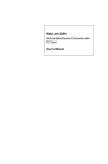
)"86&/
6& %' R<R ' ' %$ ' /&%' %% % @#'
'
(,?=,&%'''2'#'0%'&2%%
2#0'%'
%'RR''
!
STANDARD CMOS SETUP
INTEGRATED PERIPHERALS
BIOS FEATURES SETUP
SUPERVISOR PASSWORD
CHIPSET FEATURES SETUP
USER PASSWORD
POWER MANAGEMENT SETUP
IDE HDD AUTO DETECTION
PNP/PCI CONFIGURATION
SAVE & EXIT SETUP
LOAD BIOS DEFAULTS
EXIT WITHOUT SAVING
LOAD SETUP DEFAULTS
ESC : Quit
$ % & ' : Select Item
F10 : Save & Exit Setup
(Shift) F2 : Change Color
3 :&; -"*
SBC84500 User’s Manual
)81'(.9'(198.
6&%'R<R''%$'
'&#/&%'%%%@#'
'
(,?=,&%'''2#'0%2&'
''26&6'0
STANDARD CMOS SETUP
INTEGRATED PERIPHERALS
BIOS FEATURES SETUP
SUPERVISOR PASSWORD
CHIPSET FEATURES SETUP
USER PASSWORD
POWER MANAGEMENT SETUP
IDE HDD AUTO DETECTION
PNP/PCI CONFIGURATION
LOAD BIOS DEFAULTS
SAVE & EXIT SETUP
EXIT WITHOUT SAVING
LOAD SETUP DEFAULTS
ESC : Quit
$ % & ' : Select Item
F10 : Save & Exit Setup
(Shift) F2 : Change Color
)
!+
,2'#$'=
3A/
(,,#'0'
'�&#N('O
'
'#'5&$&%'#
''A,%%#%6'%%202:
!"#$
=N('O
"'
2'#'&'2'&%'
#$'&)'#''
,
%%#%6'%%202:
"%&' !"#$
(''&'##N('O
'#2N('O8A#9'&'#
8&!9$6&2'#''
,
#'0'2'89 '%2A00!'%
''&$6&0&''%''
'&#
6'0'
-(,?A(
(,?=
3:&;-"*
SBC84500 User’s Manual
)1
:
,#''''#0'/()58E//'$
6%$$'9&'0'%%6%%#&''#0'''
'
'&#?#'"/(5'''
#0'%%%''@=N<O6&#''
#0'=NO')#'@'/(5
STANDARD CMOS SETUP
INTEGRATED PERIPHERALS
BIOS FEATURES SETUP
SUPERVISOR PASSWORD
CHIPSET FEATURES SETUP
USER PASSWORD
POWER MANAGEMENT SETUP
IDE HDD AUTO DETECTION
PNP/PCI CONFIGURATION
LOAD BIOS DEFAULTS
SAVE & EXIT SETUP
EXIT WITHOUT SAVING
LOAD SETUP DEFAULTS
ESC : Quit
$ % & ' : Select Item
F10 : Save & Exit Setup
(Shift) F2 : Change Color
3 :&; -"*
SBC84500 User’s Manual
)5;<!
6&%''#'#N('O$'5%&'''&#
&'%'%%'#'D
006,
0#%%)'56'06&'&6&6'0
0#''''')'6'0,F&
'6'0'#'
STANDARD CMOS SETUP
INTEGRATED PERIPHERALS
BIOS FEATURES SETUP
SUPERVISOR PASSWORD
CHIPSET FEATURES SETUP
USER PASSWORD
POWER MANAGEMENT SETUP
IDE HDD AUTO DETECTION
PNP/PCI CONFIGURATION
$%&'!
SAVE & EXIT SETUP
LOAD BIOS DEFAULTS
EXIT WITHOUT SAVING
LOAD SETUP DEFAULTS
ESC : Quit
$ % & ' : Select Item
F10 : Save & Exit Setup
(Shift) F2 : Change Color
)(<+
5
%'2'#'#2N('O%'6&@''
'&##20
'&'265%&22%
STANDARD CMOS SETUP
INTEGRATED PERIPHERALS
BIOS FEATURES SETUP
SUPERVISOR PASSWORD
CHIPSET FEATURES SETUP
USER PASSWORD
POWER MANAGEMENT SETUP
IDE HDD AUTO DETECTION
PNP/PCI CONFIGURATION
SAVE & EXIT SETUP
LOAD BIOS DEFAULTS
()*$+
EXIT WITHOUT SAVING
LOAD SETUP DEFAULTS
ESC : Quit
$ % & ' : Select Item
F10 : Save & Exit Setup
(Shift) F2 : Change Color
3:&;-"*
SBC84500 User’s Manual
This page does not contain any information.
3 :&; -"*
SBC84500 User’s Manual
%( %
)*+
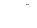
+ ?+#
,
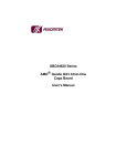
*(=?&5"''2'0,
3/,2''6'0'$#2'''2
0>&0#
*(-%%''#%'%
#20''2&'
*(
Start
↓
Un-Lock WDT
:
OUT 120H 0AH ; enter WDT function
OUT 120H 0BH ; enable WDT function
↓
Set multiple (1~4)
:
OUT 120 0NH ; N=1,2,3 or 4
↓
Set base timer (0~F)
:
OUT 121 0MH ; M=0,1,2,…F
↓
WDT counting
↓
re-set timer
:
OUT 121 0MH ; M=0,1,2,…F
↓
IF No re-set timer
:
WDT time-out, generate RESET
↓
IF to disable WDT
:
OUT 120 00H ; Can be disable at any time
8 SBC84500 User’s Manual
N
M
1
2
3
4
0
0.5 sec.
5 secs.
50 secs.
100 secs.
1
1 sec.
10 secs.
100 secs.
200 secs.
2
1.5 secs.
15 secs.
150 secs.
300 secs.
3
2 secs.
20 secs.
200 secs.
400 secs.
4
2.5 secs.
25 secs.
250 secs.
500 secs.
5
3 secs.
30 secs.
300 secs.
600 secs.
6
3.5 secs.
35 secs.
350 secs.
700 secs.
7
4 secs.
40 secs.
400 secs.
800 secs.
8
4.5 secs.
45 secs.
450 secs.
900 secs.
9
5 secs.
50 secs.
500 secs.
1000 secs.
A
5.5 secs.
55 secs.
550 secs.
1100 secs.
B
6 secs.
60 secs.
600 secs.
1200 secs.
C
6.5 secs.
65 secs.
650 secs.
1300 secs.
D
7 secs.
70 secs.
700 secs.
1400 secs.
E
7.5 secs.
75 secs.
750 secs.
1500 secs.
F
8 secs.
80 secs.
800 secs.
1600 secs.
8