1
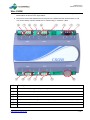
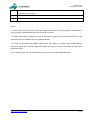
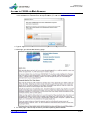
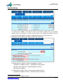
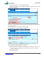
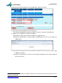
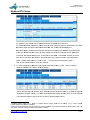
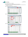
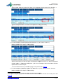
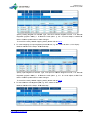
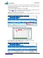
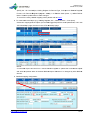
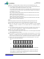
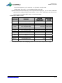
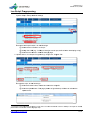
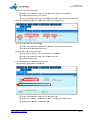
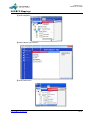
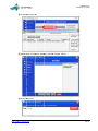
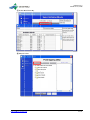
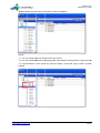
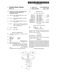
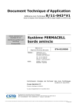
Release 3.0.0 Issued Oct 10, 2013 CSGW User Manual Wire CSGW‐‐‐‐‐‐‐‐‐‐‐‐‐‐‐‐‐‐‐‐‐‐‐‐‐‐‐‐‐‐‐‐‐‐‐‐‐‐‐‐‐‐‐‐‐‐‐‐‐‐‐‐‐‐‐‐‐‐‐‐‐‐‐‐‐‐‐‐‐‐‐‐‐‐‐‐‐‐‐‐‐‐‐‐‐‐‐‐‐‐‐‐‐‐‐‐‐‐‐‐‐‐‐‐‐‐‐‐‐‐‐ 1 Access to CSGW via Web Browser‐‐‐‐‐‐‐‐‐‐‐‐‐‐‐‐‐‐‐‐‐‐‐‐‐‐‐‐‐‐‐‐‐‐‐‐‐‐‐‐‐‐‐‐‐‐‐‐‐‐‐‐‐‐‐‐‐‐‐‐‐‐‐‐‐‐‐‐‐‐‐‐‐‐‐‐‐‐‐‐‐ 3 System Setup‐‐‐‐‐‐‐‐‐‐‐‐‐‐‐‐‐‐‐‐‐‐‐‐‐‐‐‐‐‐‐‐‐‐‐‐‐‐‐‐‐‐‐‐‐‐‐‐‐‐‐‐‐‐‐‐‐‐‐‐‐‐‐‐‐‐‐‐‐‐‐‐‐‐‐‐‐‐‐‐‐‐‐‐‐‐‐‐‐‐‐‐‐‐‐‐‐‐‐‐‐‐‐‐‐‐‐‐ 4 Modbus RTU Setup‐‐‐‐‐‐‐‐‐‐‐‐‐‐‐‐‐‐‐‐‐‐‐‐‐‐‐‐‐‐‐‐‐‐‐‐‐‐‐‐‐‐‐‐‐‐‐‐‐‐‐‐‐‐‐‐‐‐‐‐‐‐‐‐‐‐‐‐‐‐‐‐‐‐‐‐‐‐‐‐‐‐‐‐‐‐‐‐‐‐‐‐‐‐‐‐‐‐‐‐‐ 7 Troubleshooting‐‐‐‐‐‐‐‐‐‐‐‐‐‐‐‐‐‐‐‐‐‐‐‐‐‐‐‐‐‐‐‐‐‐‐‐‐‐‐‐‐‐‐‐‐‐‐‐‐‐‐‐‐‐‐‐‐‐‐‐‐‐‐‐‐‐‐‐‐‐‐‐‐‐‐‐‐‐‐‐‐‐‐‐‐‐‐‐‐‐‐‐‐‐‐‐‐‐‐‐‐‐‐15 Lua Script Programming‐‐‐‐‐‐‐‐‐‐‐‐‐‐‐‐‐‐‐‐‐‐‐‐‐‐‐‐‐‐‐‐‐‐‐‐‐‐‐‐‐‐‐‐‐‐‐‐‐‐‐‐‐‐‐‐‐‐‐‐‐‐‐‐‐‐‐‐‐‐‐‐‐‐‐‐‐‐‐‐‐‐‐‐‐‐‐‐‐‐‐‐ 17 NAE/NCE Mappings‐‐‐‐‐‐‐‐‐‐‐‐‐‐‐‐‐‐‐‐‐‐‐‐‐‐‐‐‐‐‐‐‐‐‐‐‐‐‐‐‐‐‐‐‐‐‐‐‐‐‐‐‐‐‐‐‐‐‐‐‐‐‐‐‐‐‐‐‐‐‐‐‐‐‐‐‐‐‐‐‐‐‐‐‐‐‐‐‐‐‐‐‐‐‐‐‐‐ 19 http://www.cs-controls.com Ⅰ Release 3.0.0 Issued Oct 10, 2013 Wire CSGW 1. Connect the 24 VAC supply power wires from the transformer to the 3-terminal rising clamp terminal block as shown in the figure below. 2. Connect the CAT5 cable between the RJ-45 jack on the CSGW and the network switch or hub. You cannot directly connect CSGW to a PC unless using a “crossover” cable. ⑤ ⑦ ④ ⑤ ⑤ NO. ⑧ ④ ⑤ ④ ⑥ ⑨ ④ ③ ② ① ⑩ Description ① Power LED, always on (green) if power is applied. ② 24VAC, 3-terminal rising clamp terminal block. ③ FAULT LED, red to indicate fault status ④ EOL (End Of Line) indicator, yellow when the switch is ON. ⑤ Communication LED. TX, in green, for sending message; RX, in red, for receiving message. ⑥ COM4 is RS485 port, only available for CSGW-4. ⑦ COM3 is RS485 port, available for CSGW-3 and CSGW-4. http://www.cs-controls.com 1/ 23 Release 3.0.0 Issued Oct 10, 2013 ⑧ COM1 is RS485 port, can work as MS/TP on CSGW-1/CSGW-2/CSGW-3, or can be connected to RS485 bus on CSGW-4. ⑨ COM 2 is RS485 port, available for CSGW-2/CSGW-3/CSGW-4. ⑩ RJ45 Ethernet Port. NOTE: <1> If the yellow Link LED is not on, check the cable to make sure it is connected properly. It should be on any time power is applied and an Ethernet connection is present. <2> CSGW takes about 45 seconds to boot up after power is applied. The Fault LED should be on and web access won’t be available until it is completely started. <3> There are RESTORE and RESET buttons within the housing. To restore factory default settings, remove the upper cover, press the RESTORE button and hold for more than 5 seconds, and then press the RESET button. <4> To restart CSGW, you can re-applied power to the device or press the RESET button. http://www.cs-controls.com 2/ 23 Release 3.0.0 Issue ed Oct 10, 201 13 Acces ss to CSGW via Web W Bro owser 1. Launch the browser b (pre eferably IE8 or o Google Ch hrome), and enter “http:///192.168.0.123/” as URL in the addre ess bar. Auth hentication is s required be efore you can n access the device. 2. Type in “sys stem” as use er name and “root” as pa assword to lo ogin the devicce. y will see the t following page: 3. After login, you n is provided explaining fu unctionalitiess. 4. For each page, a Quick Help section http://www ww.cs-controls..com 3/ 23 Release 3.0.0 Issue ed Oct 10, 201 13 Syste em Setup p 1. Change IP address: a Sys stem Setup> Setup> Loca al Host To change the IP add dress of the device, entter new IP address, a sub bnet mask, and gatewa ay address, th hen click "change IP". C SGW can also acquire an IP addre ess from DHCP server by b leaving the IP address empty. e IP ad dress chang ge will take efffect upon ne e xt power cy ycle. 2. Setup BACn net Paramete ers: System S Setup> Setup> BACnet Settings S To enable BACnet B IP ne etwork, speciffy the param meters as follo ows: ① BAC Cnet IP Netw work Numberr = 1 (Enable es BACnet IP P Network). ② MS S/TP Network k Number = 0 (Disables MS/TP M Netwo ork). ③ Clicck the save button. b To enable BACnet B MS/T TP1 network, specify the parameters p as a follows: ④ BAC Cnet IP Netw work Numberr = 0 (Disables BACnet IP Network). 1 Settingss about MS/TP P does not app ply to CSGW--4. http://www ww.cs-controls..com 4/ 23 Release 3.0.0 Issue ed Oct 10, 201 13 ⑤ MS S/TP Network k Number = 1 (Enables MS/TP M Netwo ork). ⑥ Spe ecify a MS/TP MAC Addrress to CSGW W and make e sure it is un nique on the MS/TP trunkk. ⑦ Clicck the save button. b If there’re more than one e CSGWs co onnected on the t BACnet network, ma a ke sure everry CSGW ha as a unique De evice Instance. Click the savve button to save change es before lea aving the pag ge. guration File: System Settup> Setup> Config File 3. Save Config Be sure to save any changes you ma ade using the e save button. You can also o save the cu urrent config guration to a new file: ① Typ pe new file name in the e input box following th he “Create nnew file” che eck box. It is sug ggested to on nly contain a lphanumeric c characters (e.g.: ( test123 3.db) in the file f name. ② Che eck “Create new n file”. ③ Clicck the save button. b http://www ww.cs-controls..com 5/ 23 Release 3.0.0 Issue ed Oct 10, 201 13 4. Upload and Download Configuration C File: System m Setup> Setup> Config File To back up the t current configuration c , do the followings: ① Clicck the downlo oad button, and a then cho oose a directory to save the t configura ation file. To upload a new configu uration file2, d do the follow wings: ② Clicck the browse button, bro owse and sellect the confiiguration file.. ③ Clicck the uploa ad button. A page (show wn as figure e below) will show up to o indicate th he uplo oad result. ④ Clicck on the dro op-down list of “Local file e directory” to t select the configuratio on file you jusst uplo oaded, and load it. ⑤ Clicck on the bo oot button to make it as the default configuration c n, which will be loaded as a the device starts up. 2 Configuration files can be download ded or created d by CSGWTo ool. For more information off CSGWTool, please refer to o CSGW T Tool User Manual. http://www ww.cs-controls..com 6/ 23 Release 3.0.0 Issue ed Oct 10, 201 13 Modb bus RTU Setup 1. Setup Modb bus RTU Local Device pa arameters: Modbus> Mod dbus RTU Seetup> Local Device D For CSGW-1, only COM M2 can be spe ecified from the t COM Po ort drop downn list. For CSGW-2 2/CSGW-3/C CSGW-4, ple ease select a COM Port to t configure its paramete ers. RTU Datta a and Setup pages only sh how objects a associated with w the curre ent selected C COM port. P Data Bits and Sto p Bits should d be the sam me as the Mo odbus slave connected c Baud Rate, Parity, to the bus. Default D Poll Rate R and Polll Delay can be b fine-tuned d according tto specific ap pplication in the field. The T default settings s are: 10 seconds for Poll Rate e, 1 second fo for Timeout, and 0.05 seconds for Poll Delay. For F Modbus devices thatt can only support functio on code 05/06 when written, plea ase check the e box of “Use e FC 5/6 …” and specify the starting unit u number . Click on the update butto on to save yo our settings. d inpu ut registers (1 1X reference es, e.g.: BI6, 10003 of sla ave 1): 2. To create mappings for discrete Modbus> Modbus M RTU Setup> RTU U Read Map Specify Discrete Input fo or Remote T Type, Bit from m Remote Re egister Form mat, 1 for Rem mote Registe er 0003), 1 for R Remote Unitt# (Modbus slave s addresss), BI 6 for Local Objectt# #3 (Modbus Register 10 S-F for Name4 (BACnet ob bject name). (Local BACnet Object), and 01TP-S 3 Registe er number sta arts from 1, equals e to regiister address (which starts s from 0) add ding 1. E.g.: 10003, registe er number 3 represents re egister addres ss 2. 4 Name sshould be shorrt (less than 14 4 characters),, plain and sim mple. Suggeste ed characterss are alphanum meric, dash, do ot, and spacce, otherwise it might not be e correctly sho own in MSEA. http://www ww.cs-controls..com 7/ 23 Release 3.0.0 Issue ed Oct 10, 201 13 Click the up pdate button to save chan nges. To check whether w the newly created d mapping works, do the followings: ① Connectt CSGW to PC P using a “S Serial to USB B” cable with RS485 convvertor, find out o the correcct COM po ort for the ca able on PC. ② Run a Modbus M slave e simulator (e e.g.: mod_RS Ssim.exe). ③ Select and a Setup the e serial port parameters accordingly. a ④ Select Digital D Inputs from the I/O O dropdown list, and set 10003 to 1. http://www ww.cs-controls..com 8/ 23 Release 3.0.0 Issue ed Oct 10, 201 13 ⑤ On CSG GW, Modbus> > Modbus RT TU Data> RT TU Registers s, Register D Data of BI 6 should s be 1. ⑥ Click the e update buttton, Time sin nce Last upd date will chan nge periodicaally. 3. To create mappings for coil c registers s 5 (0X referen nces, e.g.: BI1, 00001 of slave 1): Modbus> Modbus M RTU Setup> RTU U Read Map Specify Coiil (output) for Remote Tyype, Bit for Remote R Reg gister Formatt, 1 for Remote Registerr# (register: 00 0001), 1 for Remote R Unitt# (slave: 1), BI 1 for Local Object, 01 1CV-S for Na ame. Click th he update button to save changes. To check whether w the newly created d mapping works, please refer to Partt 2. 4. To create mappings for holding h regissters (4X refe erences, e.g..: MI1, 40007 7 of slave 1, UInt166): Modbus> Modbus M RTU Setup> RTU U Read Map 5 Coil registers supportt not only read d but also writtten, as well as s holding regis sters. UInt16 ((16-bit unsigne ed integer) is one of the da ata formats. Fo or more inform mation about th he data forma ats, please refe er to Part 10 0. 6 http://www ww.cs-controls..com 9/ 23 Release 3.0.0 Issue ed Oct 10, 201 13 Specify Holding Register for Remo ote Type, UInt16 for Remote Registter Format, 7 for Remotte ( 400 007), 1 for Remote R Uni t# (slave: 1)), MI 1 for L Local Object, 01MOD fo or Register# (register: Name. Clickk the update button to sa ave changes.. To check if the newly crreated mapp ing works, pllease refer to o Part 2. 5. To create mappings for input registerrs (3X refere ences, e.g.: A AI1, 30001 off slave 1, Yo ork-Sp16): M RTU Setup> RTU U Read Map Modbus> Modbus Specify Inp put Register for Remote Type, York-Sp16 for Re emote Regisster Format, 1 for Remotte Register# (register: ( 300 001), 1 for Remote R Uni t# (slave: 1)), AI 1 for LLocal Objectt, 01RM-T fo or Name. Clickk the update button to sa ave changes.. To check if the newly crreated mapp ing works, pllease refer to o Part 2. ues to Coil Registers R (BO O, e.g.: BO1, 00002 of sla ave 1): 6. To write valu Modbus> Modbus M RTU Setup> RTU U Write Map http://www ww.cs-controls..com 10/ 23 Release 3.0.0 Issue ed Oct 10, 201 13 Specify BO 1 for Local Object, Coil (output) for Remote Typ pe, Bit for Re emote Regis ster Format, 2 02), 1 for Re emote Unit# (slave: ( 1), 01 1SF-C for Na ame. Click th he for Remote Register# (rregister: 0000 update button to save changes. he newly crea ated mapping g works, do the following gs: To check th ① Refer to o Part 2, conn nect “Serial tto USB” cable with RS485 convertor, and setup th he serial portt parameters accordin ngly in the M Modbus simullator (e.g.: ModSim.exe).. C Outputs from f the I/O dropdown lis st. ② Select Coil ③ Modbuss> Modbus RTU R Data> RTU R Registerrs, enter 1 in Register Da ata of BO 1, check the up pdate checkbox, click k the update button. M ④ On the Modsim.exe Window, vallue of Coil 2 should be 1. 7. To write presset value to Holding Reg gisters (AO, e.g.: e 40005 of o slave 1, Yoork-Sp16): Modbus> Modbus M RTU Setup> RTU U Write Map http://www ww.cs-controls..com 11/ 23 Release 3.0.0 Issue ed Oct 10, 201 13 Specify AO 1 for Local Object, O Hold ing Register for Remote Type, York-S Sp16 for Rem mote Registe er f Remote Register# R (re egister: 4000 05), 1 for Re emote Unit# (slave: 1), 0 01RM-TSP fo or Format, 5 for Name. Clickk the update button to sa ave changes.. To check if the newly crreated mappiing works, pllease refer to o Part 6. ead-write Object (e.g.: Ho olding Registter, AO 1, 40005 of slavee 1, York-Sp1 16): 8. To create re Create two mappings fo or the object (AO and BO O suggested) with the sam me paramete ers, one in th he W Map” page. “RTU Read Map” page, the other in the “RTU Write NOTE: e object can n read from a remote Mo odbus registter to updatee the local BACnet B objecct A read-write and write th he present value v of the local l BACne et object whe enever it is cchanged by other BACne et devices. 9. Detailed mapping configuration: ① ③ ② ④ ⑤ http://www ww.cs-controls..com 12/ 23 Release 3.0.0 Issued Oct 10, 2013 ① Bit mask:4 hexadecimal digits. Usually it’s used to remove undesired bits from data. e.g.: AI3 is mapped to Modbus register 30002 and only the lower byte is needed. Bit mask is set to 00FF. Register value A1B2H will be evaluated to 178 (i.e. B2H). AI4 is mapped to Modbus register 30002 and only the higher byte is needed. Bit mask is set to FF00 and scale is set to division 256 (i.e. right shift by 8 bits). Register value A1B2H will be evaluated to 161 (i.e. A1H). BI2 is mapped to Modbus register 40003 and only bit 0 is needed. Bit mask is set to 0001. Register value 8001H will be evaluated to 1. BI3 is mapped to Modbus register 40003 and only bit 5 is needed. Bit mask is set to 0020. Register value 8001H will be evaluated to 0. BI4 is mapped to Modbus register 40003 and only bit 15 is needed. Bit mask is set to 8000. Register value 8001H will be evaluated to 1. NOTE: For non-binary objects, bit mask is often used together with scale to get the proper value. For binary objects, please select Int16 or UInt16 as data format if you specify a bit mask. ② Scale: if the scale value is not zero, register value will be multiplied by it (if the multiplying radio box is selected), or divided by it (if the division radio box is selected). Default is multiplying. e.g.: AI5 is mapped to Modbus register 30003 and one-tenth of the register value is desired. The scale value is set to multiplying and 0.1. Register value 00C8H will be evaluated to 20. ③ Offset: if set, it will be added to the register value. e.g.: AI6 is mapped to Modbus register 30003. Offset is set to -0.5, and then register value 000AH will be evaluated to 9.5 (i.e. 10-0.5). ④ Free expression: For cases that cannot be processed by above parameters, you can use free expression. For detailed information about supported math functions and operators,please refer to the Quick Help within the page. x represents the initial value reading from the register. e.g.: Below is the format representing temperature in a communication protocol, TH-TL is the higher byte and lower byte respectively. TH : BIT7 BIT6 BIT5 BIT4 BIT3 BIT2 BIT1 BIT0 0 0 1 0 F T6 T5 T4 BIT7 BIT6 BIT5 BIT4 BIT3 BIT2 BIT1 BIT0 T3 T2 T1 T0 LT1 LT2 LT3 LT4 TL : TH – F (BIT3): sign bit, 1 means negative temperature, 0 means positive temperature. BIT7BIT4 in TH: reserved, always 0010. BIT2 BIT0 in TH: the higher 3 bits of temperature data, T6 (BIT2) is the highest bit. BIT7 BIT0 in TL: the lower 8 bits of temperature data, LT4 (BIT0) is the lowest bit. The temperature resolution is 0.0625 ℃ (1/16 ℃). http://www.cs-controls.com 13/ 23 Release 3.0.0 Issued Oct 10, 2013 Apply free expression as (1-2*extract(x, 11, 1))*band(x, 2047)*0.0625 (Initial value: TH=01 H, TL= 76 H, evaluated value is 23.375) ⑤ Customized poll time: Depending on how important the mapping is, you can set a customized repeat time for polling (smaller means faster). If set to zero, default poll rate will be used, which is set on the Modbus RTU Setup ->Local Device page. 10. Examples of Data Formats: Initial Data Present Value (Hexadecimal) (Decimal) Data Format Description Int16 16-bit, signed integer FF00 -256 UInt16 16-bit, unsigned integer FF00 65,280 Int32 32-bit, signed integer FF00 1111 -16,772,847 UInt32 32-bit, unsigned integer FF00 1111 4,278,194,449 Int64 64-bit, signed integer FFFF FFFF FFFF 0000 -16 UInt64 64-bit, unsigned integer 0000 0001 0000 0000 4,294,967,296 Float32 32-bit, IEEE 754 single precision 615B 3F6C 0.9234 Float64 32-bit, IEEE 754 double precision 6B2F 7873 2CB9 F840 101266.78 Bit 0 or 1 1 1 York-Sp16 16-bit, Hi=Int, Lo=Dec 1905 25.5 BCD16 16-bit 8421 BCD code 1234 1,234 BCD32 32-bit 8421 BCD code 1234 5678 12,345,678 11. For detailed information about Mapping, please refer to the Quick Help within the page. http://www.cs-controls.com 14/ 23 Release 3.0.0 Issue ed Oct 10, 201 13 Troub bleshooting 1. When Mod dbus Mapping gs done, con nnect a CSG GW to actual Modbus devvices. 2. To check the reliability and status fllags(e.g.: BI)): Data Objec ct> Binary> IInput Objects s Click the update button n continuoussly. Reliability y should be “0” “ and Statuus Flags “x, 0 0, 0, x” (valu ue of x can be e ignored). If not, please refer to the Quick Q Help within w this pag ge for more information. 3. To check the time since e last update e(only for rea ad map): Modbus> Modbus M RTU U Data> RTU U Registers Click the update butto on continuou usly. The va alue of Time since Lasst update sh hould chang ge ase check the e wiring and devices. periodicallyy. If not, plea http://www ww.cs-controls..com 15/ 23 Release 3.0.0 Issue ed Oct 10, 201 13 4. To check the error code es: Modbuss> Modbus RTU R Data> Error Codes. Click the update u button n continuoussly. The valu ue of Total Messages M shhould be incrreasing, whille value of No N Response es, value of CRC Errors s and value of Exceptionn always sho ow “0”. If no ot, please che eck Read/Wrrite Error and d refer to the Quick Help within w the pa age for more information. http://www ww.cs-controls..com 16/ 23 Release 3.0.0 Issue ed Oct 10, 201 13 Lua S Script Pro ogramming 1. Enable Lua Script7 function: up> Setup> Module M Settiings System Setu ③ ② ① ① T To enable Lu ua Script fun nction, do the e followings: ① Che eck the box “Enable “ Lua Script”. ② Asssign the COM M (e.g.: COM M2) to None (as ( vendor port, defined w when develo oping script). ③ Clicck the save button b in Mod dule Settings s page. 2. Upload and run Lua Scripts: Program mming> Scrip pt Lua> Prog gram File T To upload a script, do the e followings: ① Clicck the browse button, bro owse and sellect the scrip pt file. ② Clicck the upload d button. The e page (show wn as figure b below) will sh how to indic ate a the uplo oad result. 7 Lua Scrripts can be de eveloped acco ording to real need. For mo ore information n of how to dev evelop Lua scrripts for CSGW W, please re efer to the builtt-in CSGW La anguage Help.. http://www ww.cs-controls..com 17/ 23 Release 3.0.0 Issue ed Oct 10, 201 13 T To run a scriipt, do the followings: ③ Clicck on the dro op-down list of o “File” to se elect the script you just u ploaded. ④ Clicck the button n “Start” to ru n the file. ⑤ If it runs properlly, the Runniing file field will w show the e current runnning script file name. 3. Back up and d delete the script: s Progra amming> Sc cript Lua> Pro ogram File T To back up th he script, do the following gs: ① Clicck on the dro op-down list of o “File” to se elect the script you want tto back up. ② Clicck the downlo oad button to o back up. T To delete the script, do the followings:: he script is ru unning, click the stop buttton to termin nate it. ③ If th ④ Clicck on the dro op-down list o of “File” to se elect the script. ⑤ Clicck the delete button. 4. To make the e script run automatically a y at boot-up: Programmin ng > Script Lu ua > Program m File ① ② ① Clicck on the dro op-down list of o “File” to se elect the script. ② Clicck the auto button b to mak ke name of th he script disp played in the e textbox. ③ Clicck the save button b in Con nfig File page e. http://www ww.cs-controls..com 18/ 23 Release 3.0.0 Issue ed Oct 10, 201 13 NAE/N NCE Map ppings 1. Mapping thro ough IP trunk, do the foll owings: ① Insert In ntegration. ② Select Object O Type: BACnet. ③ Insert Fiield Device. http://www ww.cs-controls..com 19/ 23 Release 3.0.0 Issue ed Oct 10, 201 13 ④ Invoke Auto A Discove ery. ⑤ Select Chen C Sen Ne etwork Gatew way, and Las st Finish Done. ⑥ Inset Fie eld Points. http://www ww.cs-controls..com 20/ 23 Release 3.0.0 Issue ed Oct 10, 201 13 ⑦ Invoke Auto A Discove ery. ⑧ Map All Points. http://www ww.cs-controls..com 21/ 23 Release 3.0.0 Issue ed Oct 10, 201 13 ⑨ Now BA ACnet objects s created in CSGW C are listed in NAE//NCE. NOTE: an change na ames of devicces and units of points. <1> You ca <2> You ca an create fold ders before m mapping poin nts when devvices inserteed (shown as s figure below w). It is recom mmended to place points s into different folders if there’re a large number of pointts mapped. http://www ww.cs-controls..com 22/ 23 Release 3.0.0 Issue ed Oct 10, 201 13 2. Mapping thro ough MS/TP P trunk8, do th he followings s: ① Insert In ntegration. ② Select Object O Type: Field Bus. ③ Please refer r to Part 1. NOTE: u can add de evice directly under the FFCB trunk witth no need fo or If the superrvisor device is NCE, you adding Integ gration and Field F Bus. 8 Mapping g through MS//TP trunk does s not apply to CSGW-4. http://www ww.cs-controls..com 23/ 23