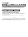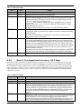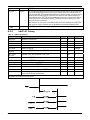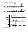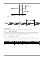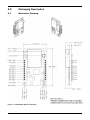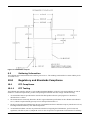
1
S M A R T M E S H® W I R E L E S S H A R T L T P 5 9 0 0 - W H M
2.4 GHz 802.15.4 Wireless Mote
About SmartMesh WirelessHART
Dust Networks’ SmartMesh® WirelessHART is an industry-leading wireless networking solution designed for critical monitoring and
control applications. WirelessHART serves a wide range of applications from renewable energy generation, such as solar and wind power,
to factory machine health monitoring and data center HVAC energy management. The SmartMesh WirelessHART system delivers
dynamic network optimization and intelligent routing to achieve unsurpassed levels of wireless network scalability, system-wide reliability
and low latency, coupled with industrial-class security. Additionally, ultra-low power operation permits even greater deployment flexibility
for wire-free applications.
Product Description—LTP5900
The LTP5900 mote module combines Dust Networks’ robust sensor networking solution breakthrough EternaTM SoC technology in an
easy-to-integrate 22-pin module. As part of the SmartMesh WirelessHART system, the LTP5900 enables customers to integrate a
standards-based wireless network into sensors and actuators to provide scalable bidirectional communications.
The LTP5900 is designed for use in line-powered, battery-powered, or energy-scavenging sensor and actuator applications that demand
reliable performance and ultra-low power operation. With Dust Networks’ innovative IEEE 802.15.4-compliant design and integrated
power amplifier, the LTP5900 enables a decade of battery life on two AA batteries. All motes function as wireless routers, enabling a
redundant, high performance, full-mesh topology.
The LTP5900 integrates all radio circuitry components, including an MMCX-type antenna connector to eliminate the need for complex RF
design. To accelerate customer development time and reduce development costs, Dust Networks provides a fully engineered RF solution,
comprehensive APIs, and complete development documentation.
Key Product Features
WirelessHART Compliance
•
Interoperable with WirelessHART Devices
Highly Scalable
•
Automatic network formation—new motes join automatically
from anywhere in the network
•
All motes are wireless routers, providing a full-mesh network
that easily scales to tens of thousands of motes per square km
• Time-synchronized communication across 15 channels
virtually eliminates in-network collisions, allowing for dense
deployments in overlapping radio space
Superior Reliability
•
SmartMesh WirelessHART Intelligent Networking Platform
enables greater than 99.99% network reliability even in the
most challenging monitoring and control environments
•
Time-synchronized channel hopping minimizes the impact of
crippling multipath interference in dynamic RF environments
LTP5900 Mote Datasheet
Dust Networks
Ultra-low Power Operation
•
Industry-leading radio technology capable of line-powered,
battery-powered, or energy-scavenging operation
•
Automatic network-wide coordination optimizes power
consumption, enabling a decade of network operation on
two Lithium AA batteries
Easy to Integrate and Deploy
•
Fully engineered RF, with power amplifier (PA), balun,
crystals, antenna matching circuitry and antenna connector
•
Comprehensive APIs provide rich and flexible functionality
to ease software development and device integration
Secure Global Market Solution
•
Fully engineered RF, with power amplifier (PA), balun,
crystals, and antenna matching circuitry
•
AES-128 bit encryption
1
Table of Contents
1.0
Absolute Maximum Ratings ................................................................................4
2.0
Normal Operating Conditions .............................................................................4
3.0
Electrical Specifications .....................................................................................5
4.0
Radio..................................................................................................................5
4.1 Detailed Radio Specifications ................................................................................ 5
4.2 Antenna Specifications......................................................................................... 6
5.0
Pinout ................................................................................................................6
5.1 LTP5900 Pinout................................................................................................... 6
6.0
Power Supply Design .........................................................................................8
7.0
Mote Boot Up......................................................................................................8
7.1 Power-on Sequence............................................................................................. 8
7.2 Inrush Current.................................................................................................... 8
7.3 Mote Boot Sequence............................................................................................ 9
7.4 Serial Interface Boot Up ......................................................................................10
7.4.1 LTP5900 Serial Interface Boot Up ...................................................................10
8.0
Interfaces ........................................................................................................10
8.1 Reset Pin ..........................................................................................................10
8.2 Timestamps ......................................................................................................10
8.3 Settable I/O Modes ............................................................................................11
8.3.1 Mode 1: Three/Four/Five-signal Serial Interface (9600 bps) ...............................11
8.3.2 Mode 3: Five-signal Serial Interface (115.2 kbps) .............................................12
8.3.3 UART AC Timing ..........................................................................................13
8.4 Mote Serial API ..................................................................................................15
8.5 Temperature Sensor...........................................................................................15
9.0
Packaging Description......................................................................................16
9.1 Mechanical Drawing............................................................................................16
9.2 Soldering Information .........................................................................................17
10.0
Regulatory and Standards Compliance .............................................................17
10.1
FCC Compliance...........................................................................................17
10.1.1 FCC Testing ................................................................................................17
10.1.2 FCC-approved Antennae ...............................................................................18
10.1.3 OEM Labeling Requirements ..........................................................................18
10.2
Industry Canada (IC) Compliance...................................................................18
10.2.1 IC Testing...................................................................................................18
10.2.2 IC-approved Antennae..................................................................................18
10.2.3 OEM Labeling Requirements ..........................................................................18
10.3
CE Compliance ............................................................................................19
10.3.1 Declaration of Conformity .............................................................................19
10.3.2 European Compliance ...................................................................................19
10.3.3 OEM Labeling Requirements ..........................................................................19
2
Dust Networks
LTP5900 Mote Datasheet
10.3.4 Restrictions.................................................................................................19
10.4
Compliance to Restriction of Hazardous Substances (RoHS) ...............................19
10.5
Industrial Environment Operation...................................................................20
10.6
Encryption Cipher ........................................................................................20
11.0
Related Documentation ....................................................................................20
12.0
Order Information............................................................................................20
LTP5900 Mote Datasheet
Dust Networks
3
1.0
Absolute Maximum Ratings
The absolute maximum ratings shown below should not be violated under any circumstances. Permanent damage to the
device may be caused by exceeding one or more of these parameters.
Unless otherwise noted, all voltages in Table 1 are made relative to VSS.
Table 1
Absolute Maximum Ratings
Parameter
Min
Typ
Max
Units
Supply voltage (VDD to VSS)
–0.3
3.76
V
Voltage on any digital I/O pin
–0.3
VDD + 0.3
V
Comments
up to 3.6
Input RF level
Input power at antenna
connector
10
dBm
+85
°C
Lead temperature
+245
°C
For 10 seconds
VSWR of antenna
3:1
±8000
V
HBM
±2
kV
HBM
±200
V
CDM
Storage temperature range
–40
ESD protection
Antenna pad
All other pads
Caution! ESD sensitive device. Precaution should be used when handling the device to prevent permanent
damage.
2.0
Normal Operating Conditions
Unless otherwise noted, Table 2 assumes VDD is 3.6 V and temperature is 25 °C.
Table 2
Normal Operating Conditions
Parameter
Operational supply voltage range
(between VDD and VSS)
Min
Typ
Max
Units
3.76
V
200
mVp-p
50 Hz to 2 MHz
1.5
V
Reset trip point
4.4
mA
Searching for network,
typically 150 ms on and
2850 ms in doze*
mA
max 750 uS + VDD rise time
from 1 V to 1.9 V.
mA
TX, 5 ms maximum
mA
TX, 5 ms maximum, +85 °C,
3.3 V
mA
TX, 5 ms maximum
1.5
uA
¯¯¯ asserted, following PoR
RST
completion
+85
°C
8
°C/min
-40 °C to +85 °C
90
% RH
Non-condensing
2.75
Voltage supply noise
Voltage supervisor trip point
Comments
Including noise and load
regulation
Peak current
During Power on Reset
12
Power amplifier enabled
9.5
Power amplifier enabled
12
Power amplifier disabled
5.2
Reset
Operating temperatures
-40
Maximum allowed temperature
ramp during operation
Operating relative humidity
10
* The duration of doze time and “on” time is determined by the joinDutyCycle command in the mote serial API. Refer to
the SmartMesh IA-510 Mote Serial API Guide for details.
4
Dust Networks
LTP5900 Mote Datasheet
Unless otherwise noted, Table 3 assumes VDD is 3.6 V.
Table 3
Current Consumption
Parameter
Min
Typ
Max
Units
Comments
Transmit
Power amplifier enabled
9.5
mA
Power amplifier disabled
5.2
mA
4.4
mA
Receive
3.0
Table 4
Electrical Specifications
Device Load
Parameter
Min
Typ
Max
Units
Comments
Total capacitance
6
µF
VDD to VSS
Total inductance
4.9
µH
VDD to VSS
Unless otherwise noted, VDD is 3.6 V and temperature is –40 °C to +85 °C.
Table 5
Digital I/O Type 1
Digital Signal
Min
Typ
Max
Units
VIL (low-level input voltage)
–0.3
0.6
V
VIH (high-level input voltage)
VDD-0.3
VDD + 0.3
V
VOL (low-level output voltage)
VOH (high-level output voltage)
0.4
VDD-0.3
Input leakage current
4.0
V
IOL(max) = 1.2 mA
V
IOH(max) = −1.8 mA
nA
25 °C
Radio
4.1
Table 6
50
Comments
Detailed Radio Specifications
Detailed Radio Specifications
Parameter
Operating frequency
Min
Typ
2.4000
Number of channels
15
Channel separation
5
Occupied channel bandwidth
Frequency Accuracy
Max
Units
2.4835
GHz
MHz
2.7
-40
MHz
+40
At –20 dBc
ppm
Modulation
Raw data rate
Comments
IEEE 802.15.4 DSSS
250
kbps
0
dBm
–95.0
dBm
–92.5
dBm
Power amplifier enabled
+8
dBm
VDD = 3.6 V, 25 °C
Power amplifier disabled
0
dBm
VDD = 3.6 V, 25 °C
Receiver operating maximum input
level
Receiver sensitivity
At 50% PER, VDD = 3 V,
25 °C
At 1% PER, VDD = 3 V,
25 °C
Output power, conducted
LTP5900 Mote Datasheet
Dust Networks
5
Parameter
Min
Typ
Max
Units
Comments
Range*
Power amplifier enabled:
Indoor
†
100
Outdoor
†
Free space
m
300
m
1200
m
25
m
200
m
350
m
25 °C, 50% RH, +2 dBi
omni-directional antenna
Power amplifier disabled:
Indoor†
Outdoor
†
Free space
* Actual RF range performance is subject to a number of installation-specific variables including, but not restricted to
ambient temperature, relative humidity, presence of active interference sources, line-of-sight obstacles, near-presence
of objects (for example, trees, walls, signage, and so on) that may induce multipath fading. As a result, actual
performance varies for each instance.
†
1 meter above ground.
4.2
Antenna Specifications
A MMCX-compatible male connector is provided on board for the antenna connection. The antenna must meet specifications
in Table 7. For a list of FCC-approved antennae, see section 10.1.2.
Table 7
Antenna Specifications
Parameter
Value
Frequency range
2.4 – 2.4835 GHz
Impedance
50 Ω
Maximum VSWR
3:1
Connector
MMCX*
* The LTP5900 can accommodate the following RF mating connectors:
• MMCX straight connector such as Johnson 135-3402-001, or equivalent
• MMCX right angle connector such as Tyco 1408149-1, or equivalent
When the mote is placed inside an enclosure, the antenna should be mounted such that the radiating portion of the antenna
protrudes from the enclosure. The antenna should be connected using a MMCX connector on a coaxial cable. For optimum
performance, the antenna should be positioned vertically when installed.
5.0
Pinout
The LTP5900 has two 11-pin Samtec MTMM-111-04-S-S-175-3 (or equivalent) connectors on the bottom side for handling
all of the I/O. The third pin in each of the connectors is not populated, and serves as a key for alignment. The connectors are
mounted on opposite edges of the long axis of the LTP5900.
5.1
LTP5900 Pinout
The LTP5900 provides a bidirectional flow-controlled serial interface (see section 8.3 Settable I/O Modes).
Table 8
6
LTP5900 Pin Functions
Pin
Number
Pin Name
1
VSS
2
VDD
3
KEY (no pin)
4
RX
5
TX
6
Reserved
Description
Ground
I/O Type
Direction
Pin State in
Deep Sleep†
Power
–
–
Power
Power
–
–
–
–
–
–
UART Rx
1
In
–
UART Tx
1
Out
VDD
No connect
–
–
–
Dust Networks
LTP5900 Mote Datasheet
Pin
Number
Pin Name
7
¯¯¯¯¯¯¯
MT_RTS
8
I/O Type
Direction
Pin State in
Deep Sleep†
UART active low mote ready to
send
1
Out
VDD
¯¯¯¯¯¯¯
MT_CTS
UART active low mote clear to
send
1
Out
VDD
9
¯¯¯¯¯¯¯
SP_CTS
UART active low serial peripheral
clear to send
1
In
–
10
¯¯¯¯
TIME
Falling edge time request
1
In
–
11
Mode_pin_B
Selects between Mode 1 & Mode
3 operation
1
In
–
12
¯¯¯¯¯¯¯¯¯¯¯¯
FLASH_P_EN
Active low flash power enable
1
In
–
13
Reserved
No connect
–
–
–
14
Reserved
No connect
–
–
–
15
Reserved
No connect
–
–
–
16
Reserved
No connect
–
–
–
17
SCK
SPI clock
1
In
–
18
MOSI
SPI master out slave in serial data
1
In
–
19
MISO
20
KEY (no pin)
21
¯¯¯¯¯¯
SPI_CS
22
¯¯¯
RST
Description
SPI master in slave out serial data
1
Out
–
–
–
–
–
Active low flash chip select
1
In
–
Active low reset
1
In
–
†
Deep sleep is the lowest possible power state, with VDD and GND connected. The mote microprocessor and radio are
inactive, and the mote must be awakened using the /RST signal (for more information see the lowPowerSleep command in
the IA-510 Mote Serial API Guide).
¯¯¯ input pin is internally pulled up and connecting it is optional. When driven active low, the mote is hardware reset
The RST
¯¯¯ pin. Note that the mote may also be
until the signal is de-asserted. Refer to section 7.1 for timing requirements on the RST
reset using the mote serial command (see the SmartMesh IA-510 Mote Serial API Guide).
¯¯¯¯ input pin is optional, and must either be driven or pulled up with a 5.1 MΩ resistor. Unless noted otherwise, all
The TIME
signals are active low.
LTP5900 Mote Datasheet
Dust Networks
7
Figure 1
LTP5900 Package with Pin Labels
6.0
Power Supply Design
Care should be taken in cases where the mote inputs will be driven to logic level high. Refer to the 040-0067 SmartMesh IA510 Mote Serial API Guide for information on mote bring-up and power cycling.
7.0
Mote Boot Up
7.1
Power-on Sequence
The LTP5900 has internal power-on reset circuits that ensure that the mote will properly boot. External resetting of the
device is not required and not recommended.
Table 9
Power-on Sequence
Parameter
¯¯¯ pulse width
RST
7.2
Min
Typ
Max
125
Units
µs
Comments
Reset timing
Inrush Current
During power on, the mote can be modeled as a lumped impedance, as shown in Figure 2. With a source impedance (Rsrc) of
1 Ω, the inrush current on the mote appears as shown in Figure 3.
8
Dust Networks
LTP5900 Mote Datasheet
Figure 2
LTP5900 Equivalent Series RC Circuit
VDD Inrush Current (Power On with Supply Impedance of 1 Ohm)
2000
1750
Current (mA)
1500
1250
1000
750
500
250
0
0
10
20
30
40
50
Time (us)
Figure 3
7.3
VDD Inrush Current
Mote Boot Sequence
Current
¯¯¯ the mote completes its boot-up process by loading the application image and loading the
Following the negation of RST
operating parameters. The LTP5900 lowers average current consumption by spreading the boot operation over time. This
method supports systems with supplies having a maximum DC current less than the peak current required by the LTP5900.
These systems must store enough charge to maintain the supply through the LTP5900’s peak current consumption. For more
information, contact your Dust Networks applications engineer. The maximum “average current” consumption for the
LTP5900 is defined by the maximum total charge Q consumed over a sliding window in time, Twindow.
LTP5900 Mote Datasheet
Dust Networks
9
Figure 4
Boot Sequence
Table 10 Boot Sequence Parameters
Parameter
Min
tboot_delay
Typ
Max
Units
Comments
3
5
s
The time between mote power greater
than 1.9 V and serial interface availability.
200
uC
Q
7.4
Serial Interface Boot Up
7.4.1
LTP5900 Serial Interface Boot Up
Twindow = 0.56 seconds
¯¯¯¯¯¯¯ line is high (inactive). The LTP5900 serial interface boots within tboot_delay
Upon LTP5900 power up, the MT_CTS
(see 7.3 Mote Boot Sequence) of the mote powering up, at which time the LTP5900 will transmit an HDLC boot event
packet. Note that full handshake is in effect and is required to receive this packet.
8.0
Interfaces
8.1
Reset Pin
The /RST input pin is internally pulled up. Connecting it is optional; however, in applications operating in the presence of
EMI, /RST should be actively driven high. When driven low, the mote hardware is in reset. Note that the mote may also be
reset using the mote reset command (0x08). For requirements on reset timing, see section 7.1.
The LTP5900 is a highly sophisticated device and Dust Networks recommends doing resets gracefully. If the device is in the
network, a disconnect command (0x07) should be issued before the /RST signal is asserted. This will result in the device
rebooting and sending the “boot” event.
The /RST signal may then be asserted since the device is not in the network.
Refer to the SmartMesh IA-510 LTP5900 Integration Guide for recommendations on how to connect to the /RST pin,
including voltage supervision. For detailed information about mote serial commands, refer to the SmartMesh IA-510 Mote
Serial API Guide.
8.2
Timestamps
The LTP5900 has the ability to deliver network-wide synchronized timestamps. The LTP5900 sends a time packet (as
described in the SmartMesh IA-510 Mote Serial API Guide) through its serial interface when one of the following occurs:
•
Mote receives an HDLC request to read time
•
¯¯¯¯ signal is asserted
The TIME
¯¯¯¯ pin is optional and has the advantage of being more accurate. The value of the timestamp is taken within
The TIME
¯¯¯¯ signal activation. If the HDLC request is used, due to packet processing the value of
approximately 1 ms of receiving a TIME
the timestamp may be captured several milliseconds after receipt of the packet. Refer to the IA-510 Mote Serial API Guide
for more information on timestamps.
10
Dust Networks
LTP5900 Mote Datasheet
Figure 5
¯¯¯¯ Pin
Operation of TIME
¯¯¯¯ Timing Values
Table 11 TIME
Variable
Description
Min
tstrobe
¯¯¯¯ strobe pulse width
TIME
tresponse
Negation of Time strobe to start of time packet
8.3
Max
125
Units
µs
100
ms
Settable I/O Modes
The LTP5900 offers a choice of two I/O modes. The functionality of the interface will be determined by the setting of
Mode pin B whose pinout is described in 5.0 Pinout.
Table 12 Mode Pin Settings
Pin
Mode pin B
Mode 1
Mode 3
Externally tied low
Externally tied high
All modes provide a means of transmitting and receiving serial data through the wireless network, as well as a command
interface that provides synchronized time stamping, local configuration, and diagnostics.
Mode 1 implements an 8-bit, no parity, 9600 bps baud three, four or five-signal serial interface with bidirectional packetlevel flow control operating at 9600 bps. In certain OEM designs, one or two of the serial handshake signals may be optional
for reduced pin count, as described in Table 13.
Mode 3 implements an 8-bit, no parity, 115.2 kbps baud five-signal serial interface with bidirectional packet-level flow
control and byte-level flow control in the mote-to-microprocessor direction only.
8.3.1
Mode 1: Three/Four/Five-signal Serial Interface (9600 bps)
The LTP5900 mode 1 provides a three, four, or five-signal serial interface that is optimized for low-powered embedded
applications (and in certain designs may provide a low pin count serial solution). The mode 1 serial interface is comprised of
¯¯¯¯¯¯¯ , MT_CTS
¯¯¯¯¯¯¯ , ¯¯¯¯¯¯¯
the data pins (TX, RX) as well as handshake pins (MT_RTS
SP_CTS) used for bidirectional flow control. The
¯¯¯¯¯¯¯
MT_RTS signal is ideal for designs where the microprocessor requires extra time to prepare to receive a packet (for example,
the OEM microprocessor sleeps periodically, but requires a wake-up signal prior to receiving a packet). Refer to Table 13 for
information on each handshake pin, including details on which pins are optional.
LTP5900 Mote Datasheet
Dust Networks
11
Table 13 Mode 1 Pin Usage
Pin
RX
I/O
Usage
Input
Serial data moving from the microprocessor to the mote.
TX
Output
Serial data moving from the mote to the microprocessor.
¯¯¯¯¯¯¯
MT_RTS
Output
¯¯¯¯¯¯¯ provides a mechanism to wake up the microprocessor in order to receive a
MT_RTS
packet. This signal is asserted when the mote is ready to send a serial packet. The signal
¯¯¯¯¯¯¯ signal from the microprocessor is detected low by the mote
stays low until the SP_CTS
(indicating readiness to receive a packet) or the
¯¯¯¯¯¯¯ times out, it will detMT_RTS to SP_CTS timeout defined in Section 8.3.3 expires. If MT_RTS
¯¯¯¯¯¯¯ to attempt to send the
¯¯¯¯¯¯¯ , wait for tMT_RTS retry and then re-assert MT_RTS
assert MT_RTS
serial packet again (see Figure 9).
¯¯¯¯¯¯¯ may be ignored by the microprocessor only if SP_CTS
¯¯¯¯¯¯¯ always stays low.
MT_RTS
¯¯¯¯¯¯¯
SP_CTS
Input
¯¯¯¯¯¯¯ provides packet-level flow control for packets transferred from the mote to the
SP_CTS
microprocessor. When the microprocessor is capable of receiving a packet it should assert
¯¯¯¯¯¯¯ signal.
the SP_CTS
¯¯¯¯¯¯¯ may be externally tied low (reducing pin count) only if the microprocessor is
SP_CTS
always ready to receive a serial packet.
¯¯¯¯¯¯¯
MT_CTS
Output
¯¯¯¯¯¯¯ provides packet-level flow control for packets transferred from the microprocessor
MT_CTS
to the mote that are destined for transfer over the network. Upon reset, following boot the
¯¯¯¯¯¯¯ until the mote establishes a wireless network connection. During
mote will negate MT_CTS
¯¯¯¯¯¯¯ if the mote does not have sufficient buffering to
operation, the mote will negate MT_CTS
¯¯¯¯¯¯¯ will also remain high if the mote is not part of the network.
accept another packet. MT_CTS
¯¯¯¯¯¯¯ pin is low before initiating each serial
The microprocessor must check that the MT_CTS
packet for wireless transmission.
¯¯¯¯¯¯¯
Note that the mote may receive local serial packets at any time regardless of the MT_CTS
state. (For a list of local commands, see the SmartMesh IA-510 Mote Serial API Guide.)
¯¯¯¯
TIME
8.3.2
Input
¯¯¯¯ pin can be used for triggering a timestamp packet. Its usage is optional.
The TIME
Mode 3: Five-signal Serial Interface (115.2 kbps)
The LTP5900 mode 3 provides a five-signal serial interface with byte-level flow control on transfers from the mote to the
¯¯¯¯¯¯¯ ,
microprocessor. The mode 3 serial interface is comprised of the data pins (TX, RX) as well as handshake pins (MT_RTS
¯¯¯¯¯¯¯ , ¯¯¯¯¯¯¯
¯¯¯¯¯¯¯ signal is ideal for designs where the microprocessor
MT_CTS
SP_CTS) used for bidirectional flow control. The MT_RTS
requires extra time to prepare to receive a packet (for example, the OEM microprocessor sleeps periodically, but requires a
wake-up signal prior to receiving a packet. Refer to Table 14 for information on each handshake pin, including details on
which pins are optional.
Table 14 Mode 3 Pin Usage
Pin
I/O
Usage
RX
Input
Serial data moving from the microprocessor to the mote.
TX
Output
Serial data moving from the mote to the microprocessor.
MT_RTS
¯¯¯¯¯¯¯
Output
MT_RTS
¯¯¯¯¯¯¯ provides a mechanism to wake up the microprocessor in order to receive a
packet. This signal is asserted when the mote is ready to send a serial packet. The signal
stays low until the SP_CTS
¯¯¯¯¯¯¯ signal from the microprocessor is detected low by the mote
(indicating readiness to receive a packet) or the tMT_RTS to SP_CTS timeout defined in
Section 8.3.3 expires. If MT_RTS
¯¯¯¯¯¯¯ times out, it will de-assert MT_RTS
¯¯¯¯¯¯¯, wait for tMT_RTS
retry and then re-assert MT_RTS
¯¯¯¯¯¯¯ to attempt to send the serial packet again (see
Figure 9).
SP_CTS
¯¯¯¯¯¯¯
Input
SP_CTS
¯¯¯¯¯¯¯ provides byte-level flow control for packets transferred from the mote to the
microprocessor. When the microprocessor is capable of receiving a packet it should assert
the SP_CTS
¯¯¯¯¯¯¯ signal. In mode 3 byte-level flow control is achieved by having the
microprocessor negate and then reassert the SP_CTS
¯¯¯¯¯¯¯ signal following the receipt of each
byte. The mote will begin transmission of the next byte after detecting the reassertion of
12
Dust Networks
LTP5900 Mote Datasheet
SP_CTS
¯¯¯¯¯¯¯.
MT_CTS
¯¯¯¯¯¯¯
Output
MT_CTS
¯¯¯¯¯¯¯ provides packet-level flow control for packets transferred from the microprocessor
to the mote that are destined for transfer over the network. Upon reset, following boot the
mote will negate MT_CTS
¯¯¯¯¯¯¯ until the mote establishes a wireless network connection. During
operation, the mote will negate MT_CTS
¯¯¯¯¯¯¯ if the mote does not have sufficient buffering to
accept another packet. MT_CTS
¯¯¯¯¯¯¯ will also remain high if the mote is not part of the network.
The microprocessor must check that the MT_CTS
¯¯¯¯¯¯¯ pin is low before initiating each serial
packet for wireless transmission.
Note that the mote may receive local serial packets at any time regardless of the MT_CTS
¯¯¯¯¯¯¯
state. For a list of local commands, see the SmartMesh IA-510 Mote Serial API Guide.
Input
TIME
¯¯¯¯
8.3.3
The TIME
¯¯¯¯ pin can be used for triggering a timestamp packet. Its usage is optional.
UART AC Timing
Table 15 UART Timing Values
Variable
Description
Min
Max
+2
Units
tRX_BAUD
Deviation from baud rate
-2
tRX_STOP
Number of stop bits (9600 bps)
1
bit period
tRX_STOP
Number of stop bits (115.2 kbps)
1.5
bit period
tTX_BAUD
Deviation from baud rate
-1
tTX_STOP
Number of stop bits
1
tSP_CTS to
MT_RTS
Assertion of SP_CTS
¯¯¯¯¯¯¯ to negation of MT_RTS
¯¯¯¯¯¯¯
0
tMT_RTS to
SP_CTS
Assertion of MT_RTS
¯¯¯¯¯¯¯ to assertion of SP_CTS
¯¯¯¯¯¯¯
+1
%
%
bit period
10
ms
500
ms
tMT_RTS retry
Time from a MT_RTS
¯¯¯¯¯¯¯ timeout to the retry.
tSP_CTS to TX
Assertion of SP_CTS
¯¯¯¯¯¯¯ to start of byte
0
500
ms
10
ms
tTX to SP_CTS
Start of byte to negation of SP_CTS
¯¯¯¯¯¯¯
1
bit period
tSP_CTS ack PW
Negation pulse width of SP_CTS
¯¯¯¯¯¯¯
500
ns
tdiag_ack_timeout*
The mote responds to all requests within this time.
125
ms
tinterbyte_timeout
Falling edge of TX to falling edge of SP_CTS
¯¯¯¯¯¯¯ (Mode 3 only)
7.1
ms
tinterpacket_delay
The sender of an HDLC packet must wait at least this amount
of time before sending another packet
20
ms
* For more information about supported requests and details on when tdiag_ack_timeout applies, refer to the
SmartMesh IA-510 Mote Serial API Guide.
LTP5900 Mote Datasheet
Dust Networks
13
Figure 6
Power-on Sequence (see section 7.3 for value of tboot_delay)
Figure 7
Byte-level Timing
tSP_CTS to MT_RTS
MT_RTS
tMT_RTS to SP_CTS
tSP_CTS ack PW
SP_CTS
tSP_CTS to TX
TX
tTX to SP_CTS
0x7E
Byte 0
0x7E
tinterbyte_timeout
Figure 8
14
Flow Control Timing
Dust Networks
LTP5900 Mote Datasheet
Figure 9
¯¯¯¯¯¯¯ Timeout Behavior
MT_RTS
Figure 10 Packet Timing
* The framing byte, 0x7E, must NOT be repeated at the start of each packet sent to the LTP5900.
8.4
Mote Serial API
The LTP5900 offers a comprehensive application programming interface (API) that provides full programmatic access to
control the mote, monitor its status (such as battery charge and network status), and provide access to the wireless mesh
network. Refer to the SmartMesh IA-510 Mote Serial API Guide for more information.
8.5
Temperature Sensor
The LTP5900 has an on-board temperature sensor. The temperature readings are available locally through the mote serial
API and through the network at the manager via the XML or serial API. For more information, refer to the SmartMesh IA510 Mote Serial API Guide, SmartMesh IA-510 Manager Serial API Guide, or SmartMesh IA-510 XML API Guide.
Table 16 Temperature Sensor
Parameter
Sensor input range
Min
Typ
-40
Accuracy
LTP5900 Mote Datasheet
Max
85
±7
Units
Comments
°C
°C
Dust Networks
15
9.0
Packaging Description
9.1
Mechanical Drawing
Figure 11 LTP5900 Mote Mechanical Drawing
16
Dust Networks
LTP5900 Mote Datasheet
Figure 12 LTP5900 Mote Footprint
9.2
Soldering Information
The LTP5900 can be hand soldered with a soldering iron at 230 °C. The soldering iron should be in contact with the pin for
10 seconds or less.
10.0
Regulatory and Standards Compliance
10.1
FCC Compliance
10.1.1
FCC Testing
The LTP5900 mote complies with Part 15.247 modular (Intentional Radiator) of the FCC rules and regulations. In order to
fulfill FCC certification requirements, products incorporating the LTP5900 mote must comply with the following:
1.
An external label must be provided on the outside of the final product enclosure specifying the FCC identifier as
described in 10.1.3 below.
2.
The antenna must be electrically identical to the FCC-approved antenna specifications for the LTP5900 as described in
10.1.2, with the exception that the gain may be lower than specified in Table 17.
3.
The device integrating the LTP5900 mote may not cause harmful interference and must accept any interference received,
including interference that may cause undesired operation.
4.
An unintentional radiator scan must be performed on the device integrating the LTP5900 mote, per FCC rules and
regulations, CFR Title 47, Part 15, Subpart B. See FCC rules for specifics on requirements for declaration of conformity.
LTP5900 Mote Datasheet
Dust Networks
17
10.1.2
FCC-approved Antennae
The following are FCC-approved antenna specifications for the LTP5900.
Table 17 FCC-approved Antenna Specifications for the LTP5900
Gain
Type
+2 dBi maximum
10.1.3
Dipole
Pattern
Omni-directional
Polarization
Vertical
Frequency
2.4-2.4835 GHz
Connector
MMCX
OEM Labeling Requirements
The Original Equipment Manufacturer (OEM) must ensure that FCC labeling requirements are met. The outside of the final
product enclosure must have a label with the following (or similar) text specifying the FCC identifier. The FCC ID and
certification code must be in Latin letters and Arabic numbers and visible without magnification.
Contains transmitter module FCC ID: SJC-LTP5900
Or
Contains FCC ID: SJC-LTP5900
10.2
Industry Canada (IC) Compliance
10.2.1
IC Testing
The LTP5900 is certified for modular Industry Canada (IC) RSS-210 approval. The OEM is responsible for its product to
comply with IC ICES-003 and FCC Part 15, Sub. B - Unintentional Radiators. The requirements of ICES-003 are equivalent
to FCC Part 15 Sub. B and Industry Canada accepts FCC test reports or CISPR 22 test reports for compliance with ICES-003.
10.2.2
IC-approved Antennae
The LTP5900 is designed to operate with antennas meeting the specifications shown in Table 18. Antennas not meeting these
specifications are strictly prohibited for use with the LTP5900. The required antenna impedance is 50 Ohms. Operation is
subject to the following two conditions: (1) this device may not cause interference, and (2) this device must accept any
interference, including interference that may cause undesired operation of the device.
Table 18 IC-approved Antenna Specifications for the LTP5900
Gain
Type
+2 dBi maximum
10.2.3
Dipole
Pattern
Omni-directional
Polarization
Vertical
Frequency
2.4-2.4835 GHz
Connector
MMCX
OEM Labeling Requirements
The Original Equipment Manufacturer (OEM) must ensure that IC labeling requirements are met. The outside of the final
product enclosure must have a label with the following (or similar) text specifying the IC identifier. The IC ID and
certification code must be in Latin letters and Arabic numbers and visible without magnification
Contains IC: 5853A-LTP5900
18
Dust Networks
LTP5900 Mote Datasheet
10.3
CE Compliance
10.3.1
Declaration of Conformity
We, Dust Networks, of 30695 Huntwood Ave, Hayward, CA 94544 USA, declare under our sole responsibility that our
product, SmartMesh IA-510 LTP5900, and in combination with our accessories, to which this declaration relates is in
conformity with the appropriate standards ETSI EN 300 328, ETSI EN 301 489-17 and EN 60950, following the provisions
of Radio Equipment and Telecommunication Terminal Equipment directive 99/5/EC with requirements covering EMC
directive 89/336/EEC, and Low voltage directive 73/23/EEC.
10.3.2
European Compliance
If the LTP5900 mote is incorporated into a product, the manufacturer must ensure compliance of the final product to the
European harmonized EMC and low-voltage/safety standards. A Declaration of Conformity must be issued for each of these
standards and kept on file as described in Annex II of the R&TTE Directive. Furthermore, the manufacturer must maintain a
copy of this LTP5900 user documentation and ensure the final product does not exceed the specified power ratings, antenna
specifications, and/or installation requirements as specified in the user manual. If any of these specifications are exceeded in
the final product, a submission must be made to a notified body for compliance testing to all required standards.
10.3.3
OEM Labeling Requirements
The ‘CE’ marking must be affixed to a visible location on the OEM product. The CE mark shall consist of the initials “CE”
taking the following form:
If the CE marking is reduced or enlarged, the proportions given in the drawing below must be respected.
The CE marking must have a height of at least 5 mm except where this is not possible on account of the nature of the apparatus.
The CE marking must be affixed visibly, legibly, and indelibly.
Furthermore, since the usage of the 2400 – 2483.5 MHz band is not harmonized throughout Europe, the Restriction sign must
be placed to the right of the ‘CE’ marking as shown below. See the R&TTE Directive, Article 12 and Annex VII for more
information.
Figure 13 CE Label Requirements
10.3.4
Restrictions
Norway prohibits operation near Ny-Alesund in Svalbard. More information can be found at the Norway Posts and
Telecommunications site (www.npt.no).
10.4
Compliance to Restriction of Hazardous Substances (RoHS)
Restriction of Hazardous Substances (RoHS) is a directive that places maximum concentration limits on the use of cadmium
(Cd), lead (Pb), hexavalent chromium(Cr+6), mercury (Hg), Polybrominated Biphenyl(PBB) and Polybrominated Diphenyl
Ethers (PBDE). Dust Networks is committed to meeting the requirements of the European Community directive 2002/95/EC.
This product has been specifically designed to utilize RoHS compliant materials and to eliminate, or reduce, the use of
restricted materials to comply with 2002/95/EC.
The Dust Networks RoHS compliant design features include:
•
RoHS compliant solder for solder joints
•
RoHS compliant base metal alloys
•
RoHS compliant precious metal plating
•
RoHS compliant cable assemblies and connector choices
LTP5900 Mote Datasheet
Dust Networks
19
10.5
Industrial Environment Operation
The LTP5900 is designed to meet the specifications of a harsh industrial environments which includes:
•
Shock and Vibration—The LTP5900 complies with high vibration pipeline testing, as specified in IEC 60770-1.
•
Temperature Extremes—The LTP5900 is designed for industrial storage and operational temperature range of –40 °C
to +85 °C.
10.6
Encryption Cipher
The LTP5900’s 128-bit Advanced Encryption Standard (AES) cipher has been certified compliant to the United States
National Institute of Standards and Technology (NIST) FIPS-197 (NIST certificate number, AES: 1437). To view the FIPS197 validation list, go to: http://csrc.nist.gov/groups/STM/cavp/documents/aes/aesval.html
11.0
•
•
•
Related Documentation
SmartMesh LTP5900 Integration Guide
SmartMesh WirelessHART Mote CLI Guide
SmartMesh WirelessHART Mote API Guide
12.0
Order Information
LEAD FREE FINISH
LTP5900IPC-WHMA???#PBF
PART
MARKING*
LTP5900
PACKAGE
DESCRIPTION
22-Lead (39mm x
24.4mm) PCB
TEMPERATURE
RANGE**
-40 °C to 85 °C
** See http://www.linear.com/ or contact your sales representative to determine the three digit software version field, ???.
For more information on lead free part marking, go to: http://www.linear.com/leadfree/
20
Dust Networks
LTP5900 Mote Datasheet
Trademarks
SmartMesh Industrial and Eterna are trademarks of Dust Networks, Inc. The Dust Networks logo, Dust, Dust Networks, and SmartMesh are registered
trademarks of Dust Networks, Inc. All third-party brand and product names are the trademarks of their respective owners and are used solely for
informational purposes.
Copyright
This documentation is protected by United States and international copyright and other intellectual and industrial property laws. It is solely owned by
Dust Networks, Inc. and its licensors and is distributed under a restrictive license. This product, or any portion thereof, may not be used, copied, modified,
reverse assembled, reverse compiled, reverse engineered, distributed, or redistributed in any form by any means without the prior written authorization of
Dust Networks, Inc.
RESTRICTED RIGHTS: Use, duplication, or disclosure by the U.S. Government is subject to restrictions of FAR 52.227-14(g) (2)(6/87) and FAR
52.227-19(6/87), or DFAR 252.227-7015 (b)(6/95) and DFAR 227.7202-3(a), and any and all similar and successor legislation and regulation.
Disclaimer
This documentation is provided “as is” without warranty of any kind, either expressed or implied, including but not limited to, the implied warranties of
merchantability or fitness for a particular purpose.
This documentation might include technical inaccuracies or other errors. Corrections and improvements might be incorporated in new versions of the
documentation.
Dust Networks does not assume any liability arising out of the application or use of any products or services and specifically disclaims any and all
liability, including without limitation consequential or incidental damages.
Dust Networks products are not designed for use in life support appliances, devices, or other systems where malfunction can reasonably be expected to
result in significant personal injury to the user, or as a critical component in any life support device or system whose failure to perform can be reasonably
expected to cause the failure of the life support device or system, or to affect its safety or effectiveness. Dust Networks customers using or selling these
products for use in such applications do so at their own risk and agree to fully indemnify and hold Dust Networks and its officers, employees,
subsidiaries, affiliates, and distributors harmless against all claims, costs, damages, and expenses, and reasonable attorney fees arising out of, directly or
indirectly, any claim of personal injury or death associated with such unintended or unauthorized use, even if such claim alleges that Dust Networks was
negligent regarding the design or manufacture of its products.
Dust Networks reserves the right to make corrections, modifications, enhancements, improvements, and other changes to its products or services at any
time and to discontinue any product or service without notice. Customers should obtain the latest relevant information before placing orders and should
verify that such information is current and complete. All products are sold subject to Dust Network's terms and conditions of sale supplied at the time of
order acknowledgment or sale.
Dust Networks does not warrant or represent that any license, either express or implied, is granted under any Dust Networks patent right, copyright, mask
work right, or other Dust Networks intellectual property right relating to any combination, machine, or process in which Dust Networks products or
services are used. Information published by Dust Networks regarding third-party products or services does not constitute a license from Dust Networks to
use such products or services or a warranty or endorsement thereof. Use of such information may require a license from a third party under the patents or
other intellectual property of the third party, or a license from Dust Networks under the patents or other intellectual property of Dust Networks.
Dust Networks, Inc is a wholly owned subsidiary of Linear Technology Corporation.
© Dust Networks, Inc. 2012. All Rights Reserved.
Document Status
Product Status
Definition
Advanced Information
Planned or under development
This datasheet contains the design specifications for product
development. Dust Networks reserves the right to change
specifications in any manner without notice.
Preliminary
Engineering samples and
pre-production prototypes
This datasheet contains preliminary data; supplementary data will
be published at a later time. Dust Networks reserves the right to
make changes at any time without notice in order to improve
design and supply the best possible product. The product is not
fully qualified at this point.
No Identification Noted
Full production
This datasheet contains the final specifications. Dust Networks
reserves the right to make changes at any time without notice in
order to improve design and supply the best possible product.
Obsolete
Not in production
This datasheet contains specifications for a product that has been
discontinued by Dust Networks. The datasheet is printed for
reference information only.
LTP5900 Mote Datasheet
Dust Networks
21