1
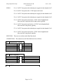
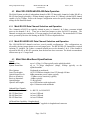
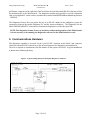
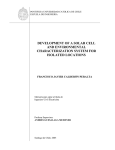
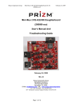
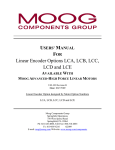
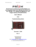
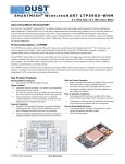
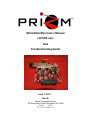
Mini4 Data Mux User’s Manual
(201780-xxx)
And
Troubleshooting Guide
June 7, 2010
Rev B
Moog Components Group
750 West Sproul Road, Springfield, PA 19064
E-Mail:
URL:
Tel: 610-328-4000 Fax:
Moog Components Group
Mini4 Data Mux, Rev B
(201780-xxx)
June 7, 2010
TABLE OF CONTENTS
Mini4 Data Mux Board P/N – 201780-xxx ...................................................................................................................... 3
Mini4 Revision History ................................................................................................................................................... 3
Mini4 Data Mux Board Dash (-) Number Definitions ..................................................................................................... 3
Mini4 Data Mux Board Operation ................................................................................................................................... 3
4.1 Mini4 Data Mux Board Indicator and Controls ....................................................................................... 4
4.2 Mini4 RS-232/RS-485/RS-422 Data Operation..................................................................................... 10
4.2.1
Mini4 RS-232 Data Channel Selection and Operation ................................................................................... 10
4.2.2
Mini4 RS-485/RS-422 Data Channel Selection and Operation ...................................................................... 10
4.3 Mini4 Data Mux Board Specifications .................................................................................................. 10
4.4 Mini4 Data Mux Board Dimensions ...................................................................................................... 11
4.5 Mini4 Data Mux BoardPower Requirements ......................................................................................... 11
4.6 Power Section Testing ........................................................................................................................... 11
4.7 Optical Section Testing .......................................................................................................................... 12
4.8 Data Section Testing .............................................................................................................................. 12
4.9 Stack Mini4 System Installation Checkout Procedure ........................................................................... 13
5
Diagnostics Overview .................................................................................................................................................... 13
6
Communications Hardware ............................................................................................................................................ 14
1
2
3
4
Manual Revisions:
August 7, 2008
September 17, 2008
June 7, 2010
Rev A - Preliminary manual
Rev A - corrected various sections
Rev B - corrected J6 connector pinout
Page 2 of 14
Moog Components Group
Mini4 Data Mux, Rev B
(201780-xxx)
June 7, 2010
1 Mini4 Data Mux Board P/N – 201780-xxx
The Mini4 Data Mux boards are typically used as a set. This board set provides for 4 channels of
RS232 data and 4 channels of RS422/RS485 data. In addition, the Mini4 Data Mux boards provide for
the use of one or more daughterboards for additional data channels.
NOTE: For details on a specific daughterboard, refer to the daughterboard manual. For a current list
of available daughterboards, please contact the factory sales personnel.
2 Mini4 Revision History
The Mini4 Data Mux board (201780-xxx) has gone through the following printed circuit board (PCB)
revisions:
PCB Revision A
PCB Revision 01
Original design, not currently in production.
Respin to correct routing.
3 Mini4 Data Mux Board Dash (-) Number Definitions
The Mini4 Data Mux boards have a Dash Number appended to the part number. This Dash Number
identifies the specific board configurations:
-01 Subsea Bottle custom version.
-02 Surface custom version.
-001 Standard version.
4 Mini4 Data Mux Board Operation
The Mini4 Data Mux boards include the fiber optic link interface, 4 channels of RS-232 data and 4
channels of RS-485 or RS-422 data. The boards interface to all of the on-board peripheral devices (such
as the fiber optic link chips (SERDES) and the data interface chips) through a programmable logic device.
The boards also provide the interface for a daughterboard connection. A block diagram of the basic Mini4
Data Mux Board I/O is shown on the following page and explained in the subsequent paragraphs.
The transmit portion (uplink from vehicle to surface) of the Mini4 Data Mux board takes in the 8 onboard
serial data signals and the daughterboard data and clock signals and converts them to a single serial
optical signal. The signal is transmitted to the Mini4 Data Mux board at the other end of the fiber optic
link in the control/viewing area. The receive portion of the Mini4 Data Mux board accepts the optical
signal, recovers the 8 serial data signals and routes them to the appropriate RS-232/RS-485/RS-422 driver
chips, and recovers the daughterboard clock and data signals and routes them to the daughterboard
connection. The downlink from the surface to the vehicle is identical to the uplink portion.
Page 3 of 14
Moog Components Group
Mini4 Data Mux, Rev B
(201780-xxx)
June 7, 2010
The Mini4 Data Mux boards require a +5VDC power source provided through the 2-pin Phoenix
connector at J5. The boards have on-board 5V to 3.3V and 2.5V converters to provide power for the
components that use these supply voltages.
4.1 Mini4 Data Mux Board Indicator and Controls
LEDS: There are 19 surface mount (SMD) LED indicators on the Mini4 Data Mux board to indicate
different statuses that are covered by function below.
Top of Board
LED
Indication
D1 (Green)
Located at the top left of the board serves as an indicator that either +5V or 3.3V dc
is available to the board connector, J2. Supply voltage (5V or 3.3V) to the daughterboard is selected via the placement of fuse F6 (3.3V) or F5 (5V)
D3 (Green)
Located on the top middle of the board, labeled „FIBR‟, provides an indication that
the transceiver module has detected the presence of an input signal on the fiber link.
When „ON‟ indicates that this board has a good level of received optical power from
the remote unit.
D6 (Green)
Labeled „2.5V‟, located on the mid-right of the board. When „ON‟ indicates the onboard 2.5V converter is operational
D7 (Green)
Not labeled, located on the bottom center of the board. When „ON‟ indicates that 5V
is available to the display LED ribbon header.
D8 (Green)
Labeled „5V‟, located on the lower right of the board. When „ON‟ indicates +5V dc
is available to the board.
D9 (Green)
Labeled „3.3V‟, located at bottom center of the board. When „ON‟ indicates 3.3V is
available on the board.
Bottom of Board
LED
Indication
D10 (Green)
Located on the upper right corner of the board, labeled “REM”. „ON‟ when the link
is established with the remote Mini4 Data Mux board and the data stream is
synchronized at the remote board‟s end.
D12 (Green)
Located on the upper left corner of the board, not labeled. When the RS-485
diagnostics processor has been accessed, this LED will toggle from “ON” to “OFF”
with each successive access.
Page 4 of 14
Moog Components Group
Mini4 Data Mux, Rev B
(201780-xxx)
June 7, 2010
D13 (Green)
Located on the upper right corner of the board, labeled “LOC”. „ON‟ when the link
is established with the remote Mini4 Data Mux board and the data stream is
synchronized at this board‟s end.
D18 (Green)
Located on the upper left of the board, labeled “TD”. „ON‟ when serial data is
being transmitted out of the board by the RS-485 diagnostics processor.
D22 (Green)
Located on the upper left of the board. „ON‟ when serial data is being received by
the RS-485 diagnostics processor.
D24
(Red/Green)
Located on the upper right of the board. Green is „ON‟ when serial data is being
received into the board on channel 8, Red is „ON‟ when serial data is being
transmitted out of the board on channel 8.
D26
(Red/Green)
Located on the upper right of the board. Green is „ON‟ when serial data is being
received into the board on channel 7, Red is „ON‟ when serial data is being
transmitted out of the board on channel 7.
D30
(Red/Green)
Located on the upper right of the board. Green is „ON‟ when serial data is being
received into the board on channel 6, Red is „ON‟ when serial data is being
transmitted out of the board on channel 6.
D31
(Red/Green)
Located on the upper right of the board. Green is „ON‟ when serial data is being
received into the board on channel 5, Red is „ON‟ when serial data is being
transmitted out of the board on channel 5.
D32
(Red/Green)
Located on the upper right of the board. Green is „ON‟ when serial data is being
received into the board on channel 4, Red is „ON‟ when serial data is being
transmitted out of the board on channel 4.
D34
(Red/Green)
Located on the upper right of the board. Green is „ON‟ when serial data is being
received into the board on channel 3, Red is „ON‟ when serial data is being
transmitted out of the board on channel 3.
D35
(Red/Green)
Located on the upper right of the board. Green is „ON‟ when serial data is being
received into the board on channel 2, Red is „ON‟ when serial data is being
transmitted out of the board on channel 2.
D36
(Red/Green)
Located on the upper right of the board. Green is „ON‟ when serial data is being
received into the board on channel 1, Red is „ON‟ when serial data is being
transmitted out of the board on channel 1.
NOTE: the fuses are the positive temperature coefficient self-resetting type and do not require
replacement
Page 5 of 14
Moog Components Group
FUSES:
Mini4 Data Mux, Rev B
(201780-xxx)
June 7, 2010
F1, a 1.5A PTC fuse protects the isolated power supply for data channels 8 & 7.
F2, a 2.6A PTC fuse protects the +5VDC input to the board.
F3, a 1.5A PTC fuse protects the isolated power supply for data channels 6 & 5.
F4, a 1.5A PTC fuse protects the isolated power supply for data channels 4 & 3.
F5, a 1.5A PTC fuse protects and selects +5VDC for the daughterboard.
Note: this fuse is replaced with a 0 ohm resistor, typically.
F6, a 1.5A PTC fuse protects and selects +3.3VDC for the daughterboard.
Note: this fuse is not placed, typically.
F7, a 1.5A PTC fuse protects the isolated power supply for data channels 2 & 1.
F8, a 1.5A PTC fuse protects and selects +5VDC for the daughterboard
Note: this fuse is not placed, typically.
SWITCHES: There are no switches on the Data Mux board.
CONNECTORS: The connectors on the Data Mux board are as follows:
J2
Daughterboard Connector
VDC Supply
RXD_DB1
GND
RXC_DB
RCV LINK
RXD_DB2
J3
o
o
o
o
o
o
o
o
o
o
o
o
2
4
6
8
10
12
VDC Supply
TXD_DB1
GND
TXC_DB
Future
TXD_DB2
o
o
o
o
o
o
o
o
o
o
2
4
6
8
10
RTGND
GND
+5V
+5V
Power /Diagnostics
RT+
GND
GND
+5V
+5V
J5
1
3
5
7
9
11
1
3
5
7
9
+5DC Power entry
Page 6 of 14
Moog Components Group
J6
Mini4 Data Mux, Rev B
(201780-xxx)
Serial Data
(RS-232) R1
GND_ISO_A
(RS-232) R2
(RS-232) R3
GND_ISO_B
(RS-232) R4
(RS-485/422) R5+
(RS-485/422) R5GND_ISO_C
(RS-485/422) R6+
(RS-485/422) R6(RS-485/422) R7+
(RS-485/422) R7GND_ISO_D
(RS-485/422) R8+
(RS-485/422) R8No Connect
1
3
5
7
9
11
13
15
17
19
21
23
25
27
29
31
33
o
o
o
o
o
o
o
o
o
o
o
o
o
o
o
o
o
o
o
o
o
o
o
o
o
o
o
o
o
o
o
o
o
o
2
4
6
8
10
12
14
16
18
20
22
24
26
28
30
32
34
T1 (RS-232)
GND_ISO_A
T2 (RS-232)
T3 (RS-232)
GND_ISO_B
T4 (RS-232)
T5+ (RS-485/422)
T5- (RS-485/422)
GND_ISO_C
T6+ (RS-485/422)
T6- (RS-485/422)
T7+ (RS-485/422)
T7- (RS-485/422)
GND_ISO_D
T8+ (RS-485/422)
T8- (RS-485/422)
No Connect
NOTE: J6 header is located at the center left side of the board.
Pin 1 is the bottom right pin – as identified by a square pad.
J6 – Board header: Amp/Tyco 1-103167-4
Mating ribbon connector: Amp/Tyco 3414-6000
Mating crimp connector: Amp/Tyco 3-87631-0 or 2-87631-9
Mating Crimp pins: Amp/Tyco 5-102095-4
J7
Led Status
GND
RLINK_LED
FIBER_LED
VID1_LED
VID3_LED
R1_LED
R2_LED
R3_LED
R4_LED
R5_LED
R6_LED
RDIAG_LED
1
3
5
7
9
11
13
15
17
19
21
21
o
o
o
o
o
o
o
o
o
o
o
o
o
o
o
o
o
o
o
o
o
o
o
o
2
4
6
8
10
12
14
16
18
20
22
22
PTC FUSE
TLINK_LED
FUTURE_LED
VID2_LED
VID4_LED
T1_LED
T2_LED
T3_LED
T4_LED
T5_LED
T6_LED
TDIAG_LED
NOTE: J7 header is located at the bottom center side of the board.
Pin 1 is the upper right pin – as identified by a square pad.
NOTE: J7 header is to be with a PRIZM display board only.
Contact PRIZM, if details are required.
Page 7 of 14
June 7, 2010
Moog Components Group
Mini4 Data Mux, Rev B
(201780-xxx)
ISP Header
J8
+3.3V
TCK
N/C
GND
1
3
5
7
o
o
o
o
o
o
o
o
2
4
6
8
TMS
TDI
TDO
NOTE: J8 to be used only by PRIZM.
JUMPERS:
There are 6 jumpers on the Mini4 Video Input with SPF Board:
(PIN 1 DENOTED BY SQUARE PCB PAD)
JP1:
RS-485/RS-422 selection for channel 8
1 o==o 2
1 o o 2
for RS-485
3 o==o 4
for RS-422
3 o o 4
JP2: RS-485/RS-422 Selection for channel 8
1 o o 2
| |
3 o o 4
1 o o 2
for RS-485
for RS-422
3 o o 4
JP3: RS-485 Receiver Termination Enable for channel 8
1 o
o2
Not terminated
JP4:
RS-485/RS-422 selection for channel 7
1 o==o 2
1 o= =o 2
Terminated
1 o o 2
for RS-485
3 o==o 4
for RS-422
3 o o 4
JP5: RS-485/RS-422 Selection for channel 7
1 o o 2
| |
3 o o 4
1 o o 2
for RS-485
for RS-422
3 o o 4
JP6: RS-485 Receiver Termination Enable for channel 7
Page 8 of 14
June 7, 2010
Moog Components Group
Not terminated
Mini4 Data Mux, Rev B
(201780-xxx)
1 o
o2
JP7:
RS-485/RS-422 selection for channel 6
1 o==o 2
1 o= =o 2
1 o o 2
for RS-485
3 o==o 4
JP8:
Terminated
for RS-422
3 o o 4
Cypress microprocessor programming header – do not use.
JP9: RS-485/RS-422 Selection for channel 6
1 o o 2
| |
3 o o 4
1 o o 2
for RS-485
for RS-422
3 o o 4
JP10: RS-485 Receiver Termination Enable for channel 6
1 o
o2
Not terminated
1 o= =o 2
Terminated
JP11: RS-485/RS-422 selection for channel 5
1 o==o 2
1 o o 2
for RS-485
3 o==o 4
for RS-422
3 o o 4
JP12: RS-485/RS-422 Selection for channel 5
1 o o 2
| |
3 o o 4
1 o o 2
for RS-485
for RS-422
3 o o 4
JP13: RS-485 Receiver Termination Enable for channel 5
1 o
o2
Not terminated
1 o= =o 2
Page 9 of 14
Terminated
June 7, 2010
Moog Components Group
Mini4 Data Mux, Rev B
(201780-xxx)
June 7, 2010
4.2 Mini4 RS-232/RS-485/RS-422 Data Operation
The Mini4 System provides 4 independent channels of RS-232 data and 4 channels of either RS-485 or
RS-422 data (jumper selectable). All data channels support at least 115.2 Kbaud, with the RS422 channel
capable of up to 2.5Mbps. Refer to the Jumper Configuration section for specific jumper definitions and
settings for the Data Mux board.
4.2.1 Mini4 RS-232 Data Channel Selection and Operation
The 4 channels of RS-232 are optically isolated in pairs (i.e. channels 1 & 2 share a common isolated
power as do channels 3 & 4). There are no baud rate jumpers to select for RS-232 operation. The
channels are simply time sampled at 12.5 mega samples per second (Msps). The maximum RS-232 data
rate is governed by the slew rate limiting on the RS-232 driver chips themselves.
4.2.2 Mini4 RS-485/RS-422 Data Channel Selection and Operation
The 4 RS-485/RS-422 channels can have several possible configurations. The configurations are
selected by placing jumper shunts on several jumper posts. The RS-485/RS-422 channels have optical
isolation (i.e. channels 1 & 2 share a common isolated power as do channels 3 & 4). If the channel is
selected for RS-485 or RS-422 operation, then the data rate does not matter. The board accommodates
all data rates up to 2.5 mega band.
4.3 Mini4 Data Mux Board Specifications
Optical
Link Data Rate:
System Frame Rate:
Fiber Options:
Laser Wavelengths:
Optical Output Levels:
Receiver Sensitivity:
Receiver Saturation:
Optical Budget:
Optical Link Lengths:
Onboard Data Channels
Number of Data Channels:
RS-232 Data Rates:
RS-485 Data Rate:
RS-422 Data Rate:
up to 1.4 Gbps, 1.0 Gbps typically on the uplink/downlink
up to 70 Mega samples/sec (Msps), 50Msps typically on the
uplink/downlink
Singlemode or multimode
All 16 CWDM wavelengths, from 1270 through 1610nm
0dBm transmitter power output, typically
-35 dBm receiver sensitivity, typically
-6 dBm, typically
35 dB, typically
up to 20 kilometers with singlemode
up to 1 kilometers with multimode
4 x RS-232, 4 x RS-485/422
At least 115Kbaud
At least 115Kbaud
At least 2.5Mbaud
Off board Data Capability - Daughterboard
Power
+5 or 3.3 VDC supplied via daughterboard connector
Page 10 of 14
Moog Components Group
Number of Data Channels
Mini4 Data Mux, Rev B
(201780-xxx)
June 7, 2010
Depends on daughterboard, refer to daughterboard manual
Remote LED Status Display Capability
J7 ribbon header carries LED status
as TTL level signals to Mini4 Display board (201650-xxx)
Misc.
Operating Temperature:
0 degree C to 65 degree C
(Except high temp version, which is -20 deg C to 70 deg C)
4.4 Mini4 Data Mux Board Dimensions
Printed circuit board (PCB): 3.55 in x 3.775 in x 0.60 in board-to-board
90.17 mm x 95.88 mm x 15.24 mm
4.5 Mini4 Data Mux BoardPower Requirements
+5 Volts at 0.75 Amps (3.5 Watts), maximum (Main board only
4.6 Power Section Testing
NOTE: There are connectors on the bottom of the Data Mux board have pins that are connected to
+5VDC and ground. If these pins are inadvertently shorted together or to a common chassis ground,
the board fuse (F2) will blow/trip.
If the +5V Power LED, +3.3V Power LED and +2.5V Power LED are out:
Check for continuity of fuse F2 with an ohmmeter.
Replace fuse if damaged.
If only the +3.3V Power LED is out:
Verify +5VDC across C21 on top of board
Verify +3.3VDC across C24 on top of board
If +3.3V is not available replace the board with a spare.
If +3.3V is available check the display LED (D9).
If only the +2.5V Power LED is out:
Verify +5VDC across C21 on top of board
Verify +2.5VDC across C17 on back of board
If +2.5V is not available replace the board with a spare.
If +2.5V is available check the display LED (D6).
If D1 is out and daughterboard operation is required:
Verify that either F6 (for +3.3VDC to D/B) or F5 (for +5VDC to D/B) is placed and is not blown
Replace fuse if damaged (it is a surface mount)
Page 11 of 14
Moog Components Group
Mini4 Data Mux, Rev B
(201780-xxx)
June 7, 2010
Verify proper voltage at connector J2
If voltage is available, check the display LED (D1).
4.7 Optical Section Testing
If the FIBER LED, RMT LINK LED and/or LOC LINK LED are off or flickering, one or more of the
following conditions is likely:
The fiber is broken or damaged.
The optical transceiver module is defective.
Excessive light loss (low received optical power) is being experienced.
The Mini4 board (not the optical transceiver module) is malfunctioning.
There is not enough attenuation in the optical link and the receiver is saturating.
If excessive optical loss is being experienced, the following conditions may be present:
Check the optical level with an optical power meter and inspect all fiber optic connections
including WDM/CWDMs and slip rings.
To determine if the fiber is broken, a laser module is out, or the board is malfunctioning, first:
Verify that the optical transceiver is tight in its socket.
Verify that shunts (jumpers) are placed per system jumper configuration.
Check all fiber optic connections including WDM/CWDMs and slip rings to make sure that they
are not causing the problem.
Check that the optical fiber cable is straight at connectors on board for minimum optic loss.
4.8 Data Section Testing
If one or more RS-232 data channels are out or has errors:
Run RS-232 data into appropriate pins of connector J6 of the channel being tested. The RS-232 data
can be input into either the remote vehicle or surface Mini4 board.
On the other end of the link, short the same pins of connector J6 of the Mini4 RS-232 channel being
tested. This will allow the two Mini4 boards to talk to each other in loop back. Both RX and TX
LEDs on both boards should be lit and/or flickering in response to the data traffic.
If the RS-232 data channel is not operating correctly, first check the RS-232. If the wiring appears
correct, then first replace the Data Mux board with a spare and check the RS-232 channel again. If
the problem is still there, return the original Data Mux board, replace the other Data Mux board with a
spare and check the RS-232 again.
If any of the LEDs are not operating correctly check one of the other channels. If the LEDs operate
on that channel, replace the Mini4 board with a spare board or use the working channels only.
If one or more RS-485 data channel is out or has errors:
Run RS-485 data into appropriate pins of connector J6. The RS-485 data can be input into either the
remote vehicle or surface Mini4 board.
Page 12 of 14
Moog Components Group
Mini4 Data Mux, Rev B
(201780-xxx)
June 7, 2010
On the other end of the link, attach the other computer used for RS-485 testing to the same pins of
connector J6 of the Mini4 RS-485 channel. This will allow the two RS-485 test computers to talk to
each other through the Mini4 boards. Both RX and TX LEDs on both boards should be lit and/or
flickering in response to the data traffic.
If the RS-485 data channel is not operating correctly, first check the RS-485 wiring then the jumpers
on both Mini4 boards. If the wiring and jumpers appear correct, then replace first the Data Mux board
with a spare and check the RS-485 again. If the problem is still there, return the Data Mux board,
replace the other Data Muxf board with a spare and check the RS-485 again.
If any of the LEDs are not operating correctly check one of the other channels. If the LEDs operate
on that channel, replace the Mini4 board with a spare board or use the working channels only.
If one or more RS-422 data channel is out or has errors:
Run RS-422 data into appropriate pins of connector J6. The RS-422 data can be input into either the
remote vehicle or surface Mini4 board.
On the other end of the link, short the TX3+ pin to the RX3+ pin and the TX3- to RX3- pins of
connector J6 of the Mini4 RS-422 channel being tested. This will allow the two Mini4 boards to talk
to each other in loop back. Both RX and TX LEDs on both boards should be lit and/or flickering in
response to the data traffic.
If the RS-422 data channel is not operating correctly, first check the RS-422 wiring then the
jumpers on both Mini4 boards. If the wiring and jumpers appear correct, then replace first the
Data Mux board with a spare and check the RS-422 again.
If the problem is still there, return the original Data Mux board, replace the other Data Mux board
with a spare and check the RS-422 again. If any of the LEDs are not operating correctly check one
of the other channels. If the LEDs operate on that channel, replace the Mini4 board with a spare
board.
4.9 Stack Mini4 System Installation Checkout Procedure
For this PC/104 stack Mini4 System installation checkout procedure, it is assumed that the Mini4 System
is composed of a Data Mux board mounted in the vehicle and a Data Mux board on the surface. +5VDC
power for the Mini Mux boards is supplied by the user‟s DC power supply. Power to be connected to the
green 2-pin Phoenix connectors located on the right side of the board (J5). Note that these boards DO
NOT have PC/104 connectors.
1. At the vehicle, mount the Mini4 Data Mux board at a convenient space within the existing PC/104
stack. The board does not use the PC/104 bus. +5VDC power must be applied to the green 2-pin
Phoenix connector J5.
2. Repeat all of the previous steps to install the Mini4 Data Mux board at the surface.
5 Diagnostics Overview
The Mini4 Video Input and Output boards have been designed to include hardware and firmware for
monitoring various real-time parameters of interest on the boar. This capability is accessed via a black3-
Page 13 of 14
Moog Components Group
Mini4 Data Mux, Rev B
(201780-xxx)
June 7, 2010
pin Phoenix connector on the right side of the board that carries bi-directional RS-485 telemetry to/from
the monitoring PC to the Mini4 boards. The diagnostics modem will typically be used in conjunction
with a user-supplied PC on the surface, which has been loaded with PRIZM Modem Monitoring software
– PMON II.
The Diagnostics feature does not require the use of an RS-485 channel in the multiplexer system for
connectivity between the topside Diagnostic PC and the remote multiplexer. The Diagnostics for the
Mini4 TRANSPARENTLY carries the local and remote diagnostics over the fiber optic link.
NOTE: The diagnostics feature in no way interferes with normal operation of the Mini4 boards
– it is not necessary to be running the diagnostics software for the Mini4 boards to work.
6 Communications Hardware
The diagnostics capability is accessed via the 3-pin RT+/RT- connector on the black 3-pin connector,
which provides the RS-485 connectivity to the on-board processor for diagnostics communications.
The user is required to communicate with the modems of the system via RS-485. A typical installations
is shown in the following drawing.
Figure 1- Typical Cabling/Wiring for Back plane Diagnostics Telemetry
Page 14 of 14