1
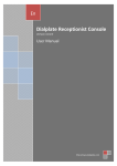
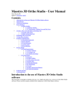
365
WARM CS-CBM CABINET
USER MANUAL AND MAINTENANCE
Index
1
2
3
4
5
NORMS AND REGULATIONS.......................................................................................................... 15
1.1
Guarantee norms:.......................................................................................................................... 15
1.2
Environmental notes:.................................................................................................................... 15
1.3
Identification: ............................................................................................................................... 15
INSTALLATION .................................................................................................................................. 16
2.1
Lifting and Movement: ................................................................................................................. 16
2.2
Positioning:................................................................................................................................... 16
2.3
Environmental Specifications:...................................................................................................... 17
2.4
Electrical Connection: .................................................................................................................. 17
FUNCTIONING.................................................................................................................................... 18
3.1
Start-up: ........................................................................................................................................ 18
3.2
Command Console: ...................................................................................................................... 18
3.3
Keyboard ...................................................................................................................................... 18
3.4
The meaning of the leds................................................................................................................ 18
3.5
How to visualise and change the set point .................................................................................... 19
3.6
The ON/OFF Function.................................................................................................................. 19
3.7
Local Alarms ................................................................................................................................ 19
3.8
Stopping the Machine:.................................................................................................................. 19
MAINTENANCE .................................................................................................................................. 20
4.1
Preliminary Operations:................................................................................................................ 20
4.2
General Cleaning: ......................................................................................................................... 20
ELECTRICAL DIAGRAMS ............................................................................................................... 21
2
INSTALLATION
This product must be installed by qualified personnel.
2.1
Lifting and Movement:
The product is to lifted by a transport vehicle using transport pallets, in the following
manner:
- Position the forks at the level of the
vehicle (e.g. lorry).
- Move forward with the transport pallet so
as to insert the forks under the cabinet.
- Ensure that the cabinet is perfectly
balanced on the forks before lifting it
(fig.2).
Fig. 2
-
Position the cabinet on the ground.
Lift the cabinet using the pallets as shown
in figure 3.
- Unscrew the screws that anchor the lists
to the base (fig.3 pos. A) and remove the
base (fig.3 pos. B).
Proceed in the same way to remove the other
base.
The cabinet must be moved manually when
on the ground.
Fig. 3
2.2
Positioning:
Please carry out the following operations to ensure correct positioning:
-
-
Fig. 4
Position the cabinet in such a way as to
leave sufficient space for use and
maintenance in conditions of safety as
foreseen by the UNIEN 292/2 norm point
6.2.1 and in paragraph 2.5
Ensure the existence of a suitable earthing
plant as foreseen by the European Norms.
Once the cabinet is placed in the
desidered area, it must be put horizontally
through the adjustable feets. (fig.4)
2.3
Environmental Specifications:
When positioning the display cabinet remember to consider that its correct operational
activity is guaranteed in temperature conditions of < 30°C and relative humidity of < 55%.
Please also ensure that:
- It is not exposed to direct sunlight;
- The air conditioning or heating in the environment where the cabinet is positioned is not
focused directly on the cabinet.
It is essential to respect the aforementioned conditions in order to avoid malfunctions, which
will not be covered by guarantee.
2.4
Electrical Connection:
Please ensure that there is a suitable earthing plant before installation, as outlined by the
current norms in the country of sale. Check that the network tension is compatible with
the characteristics outlined on the plate situated on the operator’s side of the display
cabinet (see fig.1 pag. 3). Also check to ensure that the line to which the cabinet is
connected is of the correct dimensions to support the load of the cabinet itself.
WARNING! Fluctuations in tension greater than 10% of the nominal tension indicated
on the plate may cause permanent damage to the compressor and to the other pieces of
electro-mechanical equipment that will not be covered by guarantee.
Respect any national regulations for electrical installations.
Position the general plant switch to OFF.
The display cabinet is supplied with a cable with three wires;
Yellow – Green = Earth
Blue = Neutral
Brown = Phase
WARNING! Never cut or remove the aforementioned yellow-green cable for any
reason.
The three supply cables must be connected to the main network, which must be equipped
with an efficient earthing network, in accordance with the national and local norms (where
existent) for electrical installations and they must be suitable for the electrical absorption of
the display cabinet. Please refer to the table in chapter 6 – Total Power Absorption column.
WARNING! The electrical connection to the network must be carried out by means of
the three wires included, the central plant to which the cabinet is connected must also
have a switch with contact openings measuring at least 3mm and protected by fuses.
WARNING! Apply an adequate anchoring method to the supply cable in the
connection box, making reference to the table outlined below.
NOMINAL SECTION [mm2]
NOMINAL CURRENT OF
THE APPLIANCE [A]
3
3÷6
6 ÷ 10
10 ÷ 16
16 ÷ 25
25 ÷ 32
32 ÷ 40
40 ÷ 63
FLEXIBLE CABLES
[mm2]
0,5
0,75
1
1,5
2,5
4
6
10
÷
÷
÷
÷
÷
÷
÷
÷
0,75
1
1,5
2,5
4
6
10
16
CABLES FOR EARTHING
[mm2]
1
1
1
1,5
2,5
4
6
10
÷
÷
÷
÷
÷
÷
÷
÷
2,5
2,5
2,5
4
6
10
16
25
3
3.1
FUNCTIONING
Start-up:
1)
Operate the central electrical equipment’s
main switch.
2) Operate the showcase’s main switch
behind the back protection board. Remove
the fixing screws from the back board, as
shown in picture 7 position B, and set the
main switch on the “1” position (picture 7
position A) by activating the showcase’s
electrical power supply.
3.2
Fig. 7
Command Console:
The refrigerating plant of the display cabinet is controlled by means of an electronic console.
The electronic console consists of:
1) a command console
2) a display
3.3
Keyboard
T640: tastiera orizzontale a 8 tasti
(185x38mm).
To visualise or change the set point. When programming this button is used to select a
parameter or to confirm a value.
This button is used during programming for going through the parameter codes or for
increasing their value.
This button is used during programming for going through the parameter codes or
decreasing their value.
Use this button to turn the display cabinet lights on and off.
Turn the instrument on and off.
3.4
The meaning of the leds
There are a series of luminous points on the display, the meaning of which you will find in
the table below:
LED
MODE
ON
FLASHING
ON
Function
Heating ON
Programming phase (flashing with LED )
ALARM SIGNAL
- In the “Pr2” programme it indicates that the parameter is also
present in “Pr1”
3.5
How to visualise and change the set point
1. Press the SET key and release it to see the set point: you will visualise the set point
immediately.
2. To change the set point press the SET key and keep it pressed for 3 seconds: the led will
flash
;
3. To change the value activate
4.
3.6
and
.
To memorise the new set point, press the SET key or wait 15 seconds to exit the
programming feature.
The ON/OFF Function
By pressing the ON/OFF key the instrument will show “OFF”.
In this configuration the loads of all of the regulations will be deactivated. To turn the
instrument back ON press the ON/OFF key again.
The OFF condition allows for the exclusion of the instrument from monitoring without
generating any type of alarm.
N.B. The LIGHT key remains active in the OFF position.
3.7
Local Alarms
MESSAGE
CAUSE
STATE OF OUTPUTS
“ P1 ”
Thermostat probe failure
Output according to “ Con “ and “ COF “ parameters
“ HA “
High temperature alarm
Unchanged
“ LA “
Low temperature alarm
Unchanged
“ EE ”
Memory anomaly
“ EAL “
Digital input alarm
Unchanged
“ BAL ”
Blockage alarm from digital
input
Regulation outputs deactivated
Clock alarm
Unchanged
“ rtc “
3.8
Stopping the Machine:
To stop the machine completely, activate the
switch (A) that is situated behind the back
protection panel. By removing fixing screws
of the back motor panel (as shown in picture 8
pos. B) it is possible to turn the main switch
to “0” position (see picture 8 pos. A), thus
disconnecting power supply to cabinet.
Fig. 8
4
4.1
MAINTENANCE
Preliminary Operations:
Before carrying out any preliminary maintenance or cleaning operations you must disconnect
the electricity supply by turning off the general plant switch in the room where the display
cabinet is situated.
4.2
General Cleaning:
-
Stainless steel surfaces: Clean with a sponge or a damp cloth using water and a
neutral detergent, rinse and dry off with a soft cloth.
-
Wooden surfaces: Clean with a sponge or a damp cloth using water and a neutral
detergent, rinse and dry off with a soft cloth.
-
Glass surfaces: Clean with a sponge or a damp cloth using water and a neutral
detergent, rinse and dry off with a soft cloth.
5
ELECTRICAL DIAGRAMS
ELECTRICAL DIAGRAM TCBM
The following electrical diagrams will have to be used by qualified personnel on the basis of
the current regulations in vigour in the country of sale.
ELECTRICAL DIAGRAM TCS