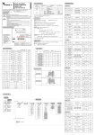
Download Series X400 Quick Start Guide
Transcript
Four push-button keys are
available:
MENU
DECREASE
INCREASE
ENTER
PASSWORD OVERVIEW:
The factory set password is 33
and can be changed for security
reasons.
• To access the ‘Configuration
Data’ listed in Section I, a
password is always needed.
• To access the ‘Parameters
Data’ listed in Section II, a
password may or may not be
needed depending on the
password used (see Password
Information).
• To access the ‘Operator
Information’ listed in Section
III, a password is not required.
PASSWORD INFORMATION:
If Password is set at 0 to 4999:
The ‘Parameters Data’ listed in
section II is available to the operator at all times. This password
is only needed to access
QUICK
START
GUIDE
M400 line
‘Configuration Data’ listed in
Section I.
If Password is set at 5000 to
9999:
The ‘Parameters Data’ listed in
Section II is NOT available to the
operator at all times. This password is needed for access to
both ‘Parameters Data’ Section
II and ‘Configuration Data’
Section I.
To Enter Known Password:
Push MENU key until ‘PASS’ is
on lower display, then press
INCREASE or DECREASE key
to known password (the factory
set password is 33), then push
ENTER key. You are now in
Configuration Data Section I.
To Change Password:
(Note: there is no need to change
the factory set password of 33
except for security reasons).
After entering known password, (if
ConF is not on lower display already)
push MENU key until ‘ConF’ is on
lower display, push ENTER key until
‘Code’ is displayed in lower display,
push INCREASE or DECREASE key
to new password, press ENTER key
to save new password. (IMPORTANT: record this new password in
a safe place for future reference !!!)
Press MENU key once to exit
Configuration Data Section I.
QSUGM400RKH -12/03/02
c
C
UL
US
LISTED
IMPORTANT
Before functioning properREAD THIS FIRST: ly in your application, you
will need to set (in order) the
controller’s:
• Password
• Configuration data (especially the software configuration code)
• Parameters data
This ‘Quick Start Guide’ will
help take you through this
process in a minimal
amount of time. References
to the larger ‘M400 User
Manual’ are used, so have
that manual available as
you read through this guide.
Additional support is available via:
• Athenacontrols.com on
the web
• Technical support on the
phone at 610-828-2490
8am to 5pm EST weekdays
• Your
local
Athena
Controls authorized representative or distributor
Section I – CONFIGURATION DATA:
Section II – PARAMETERS DATA:
Section III – OPERATOR INFORMATION:
Configuration Data is high level data that defines
how the controller reacts to your process. This
data entry requires a password. Push MENU key
once to exit Configuration.
Parameters Data is detailed data that defines
how the controller reacts to your process. This
data entry may require a password (see password overview). Depending on the software configuration code, some displays may vary. Push
MENU key 3 times to exit Parameters.
This information is always available to the operator and does not require a password.
Software Configuration Code:
This five-digit code defines type of input, control mode & output, direct/reverse action and
alarm types. This code may be changed to meet
your application. The factory set ‘Software
Configuration Code’ is 3002-3 for J thermocouple input, PID control on output #1, reverse
acting mode, output #2 as absolute high alarm,
& output #3 as absolute low alarm. To change
code; push MENU key until ‘ConF’ is displayed,
push INCREASE or DECREASE keys to code
needed, then push ENTER key to save this new
code. See M400 User Manual pages 18 & 19 for
available code listing.
To Change Engineering Units:
Press ENTER key until ‘Unit’ is displayed, push
INCREASE or DECREASE keys to desired selection, press ENTER key to save this new engineering unit. See M400 User Manual page 37
for engineering unit listing. Examples of engineering units are: ºF and ºC.
Additional configuration functions available:
# of display decimals (linear input only) +
options of : Communication baud rate, retransmission range, DI functions, timer / startup functions, & current transformer input.
See M400 User’s Manual pages 35 to 37 for a
detailed explanation of these functions.
To Display and Change Alarm Setpoint:
Push MENU key until A2SP is on lower display
(alarm 2 setpoint), press INCREASE or
DECREASE key to change upper display value
(factory default value is 32), press ENTER key
to save. Repeat for A3SP (alarm 3 setpoint).
To Start Autotune Software:
Push MENU key until ‘tune’ displays, press
INCREASE or DECREASE key to select ‘start’
or ‘stop’ (factory default value is ‘stop’), press
ENTER key. Green ‘AT’ indicator will light until
software calculation is completed.
To Enter Parameter Group 1:
Push MENU key until A2SP displays. Then press
ENTER key until ‘Pb’ displays. This group will
allow access to PID tuning, output/alarm limit
& heat/cool parameters.
See M400 User Manual pages 25 & 26 for
details.
To Enter Parameter Group 2:
Push MENU key until ‘tune’ displays. Then press
ENTER key, ‘AdPt’ displays. This parameter
group will allow access to setpoint, alarm, adaptive tuning, and option parameters.
See M400 User Manual page 26-28 for details.
Normal Display – Process Variable (PV):
The normal display shows PV (input value) in the
upper display, and SP on the lower display. On
the left part of the display; a red 1, 2, or 3 indicates that output is active. A steady green ‘MAN”
indicates manual mode, and a flashing ‘MAN”
indicates autotune software is active. See M400
user Manual page 20 for other indicators.
To Change from Auto to Manual mode:
Push the MENU key once, ‘AMan’ displays in
lower display, ‘Auto’ displays in upper display.
Push INCREASE key once, ‘Man’ displays in
upper display, press ENTER key to save entry.
Use same procedure to go back to Auto mode,
but use DECREASE key to select ‘Auto’.
To Change Setpoint (SP) Value:
Push either the DECREASE or INCREASE key to
change the SP value.
To Display PV Engineering Units:
Push ENTER key once and the type of unit will
display briefly in the lower display (examples: ºC
or ºF). This value can only be changed via password access.
To Display Output Value while in Auto mode:
Push the ENTER key twice, ‘Out’ briefly displays
on lower display with output value in the upper
display. This value can only be changed when in
the manual mode.
Athena M400 Platinum™ Controller Software Map
OPERATOR
INFORMATION
P.v.
PARAMETERS DATA
(may require password entry, see configuration data for password entry
press key Q three times to exit)
P.v.
Unit
S.P.
Out
TCur
tMr
Q = MENU key è= ENTER key $%= DECREASE/INCREASE key
Shown when in
manual mode.
Shown when in
auto mode, not
shown when
configured for
on/off controller.
A2S.P
TUne
Press $%
keys once to display value, press
$% keys
more than once
to change value.
Press $%
keys once to
display
'Strt or 'Stop
then press the
èkey to enter
your selection
P.v.
A3S.P
OPHS
A2hy
A2Lb
P.b.
AdPt
A3hY
Shown with current transformer
option.
T.i.
P.b.a
A3Lb
Shown with
timer option.
T.d.
t.i.A
tLba
t.c.
t.d.A
t.Fil
O.C.
tine
In.Sh
T.c.C.
SP2
dErr
rCGa
SL .u
StOp
hY.C
SL. d
SttM
dbnd
S.P. L.
SaOP
OP. H
S.P. H.
Addr
OP.HC
SPSU
rt.Lo
hy.
thSU
rt.Hi
Hard
Conf
rel:
Press $% keys
once to display current
S
' P value,
press $% keys
more than once to change
S
' P value.
CONFIGURATION DATA
(requires password entry
press Q key once to exit)
PASS
Press $% keys to
password value desidered,
then press the è key
to enter your selection.
ConF
Con2
tAct
Unit
Prot
Sc.dd.
baud
Sc.Lo
retr
Sc.Hi
rtH
ILFn
HtFS
tMod
Code
Note: some prompts may not appear depending on options selected and how other prompts are configured.
Detail can be found on pages 20 to
24 of the M400 User’s Manual
Details can be found on pages 25 to
34 of the M400 User’s Manual
Conf
Hard
Out
(PV)
reL.
(SP)
tCur
A2hY
A2Lb
A2SP
A3SP
A3hY
A3Lb
AdPt
Addr
dbnd
dErr
hY
hYc
InSh
O.C.
OPH
=
=
=
=
=
=
=
configuration code
hardware code
control output value in %
process variable value
software release code
setpoint value
current transformer load
current in amperes
tMr = timer remaining time
Unit = engineering unit
=
=
=
=
=
=
=
=
=
=
=
=
=
=
=
alarm 2 (AL2) hysteresis
AL2 latch/block functions
alarm 2 setpoint
alarm 3 (AL3) setpoint
AL3 hysteresis
AL3 latch/block functions
adaptive tuning
communications address
deadband (heat/cool)
error dead band
control output hysteresis
cool output hysteresis
input shift
overshoot control
control output high limit
Note: parameter listings are in alphabetical order
Details can be found on pages 35 to 45 of the
M400 User’s Manual
OPHC
OPHS
Pb
Pba
band
rCga
rtHi
rtLo
SaOp
SL.d
Sl.u
SP2
SPH
SPL
SPSU
= cool output high limit
= output high limit at startup
= proportional band
= calculated proportional
= cool relative gain
= retransmission high range
= retransmission low range
= output safety value
= setpoint ramp down
= setpoint ramp up
= stand-by setpoint value
= setpoint high limit
= setpoint low limit
= start-up setpoint
StOP
Sttm
t.c.
tcC
t.d.
tdA
tFiL
thSU
t.i.
tiA
tLbA
tiMe
Tune
= soft-start output value
= soft-start activation time
= cycle time
= cool cycle time
= derivative time
= calculated derivative time
= filter time constant
= start-up hold time
= integral time
= calculated integral time
= loop break alarm delay
= timer setting
= self-tuning prompt
baud
Code
Con2
ConF
HtFS
ILFn
Pass
Prot
(PV)
retr
rtH
Scdd
ScHi
ScLO
tAct
tMod
Unit
=
=
=
=
=
=
=
=
=
=
=
=
=
=
=
=
=
baud rate
password
alarm 3 configuration code
main configuration code
current transformer primary high range
digital input function
password entry
communications protocol
process variable value
analog output range
analog output selection
number of decimals
analog high range
analog low range
timer action
timer/startup mode
engineering units


