1
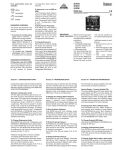
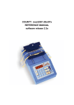
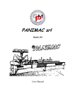
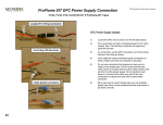
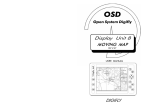
9.957.099 00
PROFLAME 2 TRANSMITTER
USE AND INSTALLATION INSTRUCTIONS
Read the instructions before use. This control must be installed in accordance with the rules in force.
9957099_00_nero_mod_05-10-2011.i1 1
05/10/2011 8.36.26
e
ol
y
a
e
y
f
.
e
t
g
A
p
PROFLAME 2 TRANSMITTER USE AND INSTALLATION INSTRUCTIONS
rt
IMPORTANT
The Proflame Transmitter 2 is an integrated part of the Proflame 2 System, which consists of these elements:
• Proflame 2 Transmitter, to be used in conjunction with:
• Integrated Fireplaces Control (Proflame 2 IFC)
The Proflame 2 Transmitter provides for controlling the following hearth appliance functions:
1. Main Burner On/Off
2. Main Burner flame modulation (6 levels)
3. Choice of standing or intermittent pilot (CPI/IPI)
4. Thermostat and Smart thermostat functions
5. Accent light modulation (6 levels)
6. Split flow valve
7. On/Off relay
8. Comfort Fan speed modulation (6 levels)
The Proflame Transmitter uses a streamline design with a simple button layout and informative LCD display
(Fig. 1). A Mode Key is provided to index between the features and a Thermostat Key is used to turn on/off or
index through Thermostat functions (Fig. 1 & 2). Additionally, a Key Lock feature is provided (Fig. 22).
Blue back lit LCD display
ON/OFF Key
THERMOSTAT Key
Up/Down Arrow Key
MODE Key
Fig. 1: PROFLAME Transmitter
9957099_00_nero_mod_05-10-2011.i2 2
05/10/2011 8.36.31
Transmission
Low battery alarm
Thermostat OFF/
ON/SMART
Room
Temperature
CPI mode
Set Point
Temperature/Level/State
Aux ON
Flame ON
Split Flow
Dimmer ON
Comfort fan
Fig. 2: Transmittter LCD display.
TECHNICAL DATA
Remote Control
Supply voltage
4.5 V (three 1.5 V AAA batteries)
Ambient temperature ratings
0 - 50 °C (32 - 122 °F)
Radio frequency
315 MHz
WARNING
PROFLAME 2 TRANSMITTER USE AND INSTALLATION INSTRUCTIONS
Key Lock
The Transmitter and Receiver are radio frequency devices.
placing the Receiver in or near metal may severely reduce the signal
range.
Attention!
- Turn “OFF” the main gas supply of the appliance during installation or
maintenance of the Receiver device.
- Turn “OFF” main gas supply to the appliance prior to removing or
reinserting the batteries.
- IN CASE OF REMOTE CONTROL MALFUNCTION TURN OFF THE IFC DEVICE USING
THE “ON/OFF” MAIN SWITCH.
- FOR INSTALLATION/MAINTENANCE SWITCH OFF THE IFC DEVICE REMOVING MAIN
POWER SUPPLY PLUG.
9957099_00_nero_mod_05-10-2011.i3 3
05/10/2011 8.36.32
T
PROFLAME 2 TRANSMITTER USE AND INSTALLATION INSTRUCTIONS
OPERATING PROCEDURE
Initializing the System for the first time
Power the receiver. Activate the procedure of the receiver address programming, see the
receiver instruction (*). The Receiver will “beep” three (3) times to indicate that it is ready
to synchronize with a Transmitter. Install the 3 AAA type batteries in the Transmitter battery
bay, located on the base of the Transmitter. (fig. 3) With the batteries already installed in
the Transmitter, push the On button. The Receiver will “beep” four times to indicate the
Transmitter’s command is accepted and sets to the particular code of that Transmitter. The
system is now initialized.
(*) The receiver may be independent or integral to the IFC hearth appliance
control module. The receiver instruction may not be independent when part
of the IFC.
Fig. 3: Battery compartment.
Temperature indication Display
With the system in the “OFF” position, press the Thermostat Key and the Mode Key at the same
time. Look at the LCD screen on the Transmitter to verify that a C or F is visible to the right of
the Room Temperature display. (Fig. 4 and fig. 5)
Fig. 4: Remote Control display in Farenheit.
Fig. 5: Remote Control display in Celsius.
Turn on the Appliance
With the system OFF, press the ON/OFF Key on the
Transmitter. The Transmitter display will show some other
active Icons on the screen. At the same time the Receiver
wil activate the appliance. A single “beep” from the
Receiver will confirm reception of the command.
Turn off the Appliance
With the system ON, press the ON/OFF Key on the
Transmitter. The Transmitter LCD display will only show
the room temperature (Fig. 6). At the same time the
Receiver will turn off the appliance. A single “beep” from
the Receiver confirms reception of the command.
9957099_00_nero_mod_05-10-2011.i4 4
Fig. 6: Remote Control display.
05/10/2011 8.36.38
The proflame has six (6) flame levels. With the system on, and the flame level at the maximum
in the appliance, pressing the Down Arrow Key once will reduce the flame height by one step
until the flame is turned off.
The Up Arrow Key will increase the flame height each time it is pressed. If the Up Arrow Key is
pressed while the system is on but the flame is off, the flame will come on in the high position.
( Fig. 7 & 8 ) A single “beep” will confirm reception of the command.
Fig. 7: Flame Off
Fig. 8: Flame level 5
Flame Level 1
Flame Level Maximum
PROFLAME 2 TRANSMITTER USE AND INSTALLATION INSTRUCTIONS
Remote‑Flame Control
Room Thermostat ( Transmitter Operation)
The Remote Control can operate as a room thermostat. The thermostat can be set to a desired
temperature to control the comfort level in a room.
To activate this function, press the Thermostat Key (Fig. 1). The Lcd display on the Transmitter
will change to show that the room thermostat is “ON” and the set temperature is now
displayed (Fig. 9). To adjust the set temperature, press the Up or Down Arrow Keys until the
desired set temperature is displayed on the LCD screen of the Transmitter.
ROOM TEMPERATURE
SET TEMPERATURE
Fig. 9
9957099_00_nero_mod_05-10-2011.i5 5
Fig. 10
05/10/2011 8.36.41
PROFLAME 2 TRANSMITTER USE AND INSTALLATION INSTRUCTIONS
Smart Thermostat (Transmitter Operation)
The Smart Thermostat function adjusts the flame height in accordance to the difference
between the set point temperature and the actual room temperatures. As the room
temperature gets closer to the set point the Smart Function will modulate the flame down.
To activate this function, press the Thermostat Key (Fig. 1) until the word "SMART" appears to
the right of the temperature bulb graphic (Fig. 11).
To adjust the set temperature, press the Up or Down Arrow Keys until the desidered set
temperature is displayed on the LCD screen of the Transmitter (Fig. 12).
Note. When Smart Thermostat is activated, manual flame height adjustment is disabled.
Fig. 11: Smart flame function
Fig. 12
Fan Speed Control
If the appliance is equipped with a hot air circulating fan, the speed of the fan can be
controlled by the Proflame system. The fan speed can be adjusted through six (6) speeds. To
activate this function use the Mode Key (fig.1) to index to the fan control icon (Fig. 13). Use the
Up/Down Arrow Keys (fig.1) to turn on, off or adjust the fan speed (fig. 14). A single “beep”
will confirm reception of the command.
Fig. 13
Fig. 14
9957099_00_nero_mod_05-10-2011.i6 6
05/10/2011 8.36.43
OP
The auxiliary function controls the AUX power outlet by the dimmable light control. To activate
this function use the Mode Key (fig. 1) to index to the AUX icon (fig. 15 & 16).
The intensity of the output can be adjusted through six (6) levels. Use the Up/Down Arrow Keys
(fig.1) adjust the output level (fig. 16). A single “beep” will confirm reception of the command.
Note. This function is available only with the IFC Control Module.
Fig. 15
Fig. 16
Split Flow control
PROFLAME 2 TRANSMITTER USE AND INSTALLATION INSTRUCTIONS
Remote dimmer control (Light)
The secondary burner is controlled by the split Flow. To activate this function use the Mode Key
(fig. 1) to index to the SPLIT FLOW mode icon (fig. 19 & 20).
Pressing the Up Arrow Key will activate the secondary burner. Pressing the Down Arrow Key
will turn the secondary burner off. A single “beep” will confirm the reception of the command.
Fig. 19
Fig. 20
9957099_00_nero_mod_05-10-2011.i7 7
05/10/2011 8.36.44
PROFLAME 2 TRANSMITTER USE AND INSTALLATION INSTRUCTIONS
Remote auxiliary relay control
The auxiliary function controls the AUX relay outlet. To activate this function use the Mode Key
(fig. 1) to index to the AUX icon (fig. 17 & 18).
Pressing the Up Arrow Key will activate the outlet. Pressing the Down Arrow Key will turn the
outlet off. A single “beep” will confirm the reception of the command.
Fig. 17
Fig. 18
Continous Pilot/Intermittent Pilot (CPI/IPI) selection
With the system in "OFF" position press the Mode Key (fig. 1) to index to the CPI mode icon
(fig. 21 & 22).
Pressing the Up Arrow Key will activate the Continous Pilot Ignition mode (CPI). Pressing the
Down Arrow Key will return to IPI. A single “beep” will confirm the reception of the command.
NOTE: If the system is equipped with a CPI/IPI toggle switch:
• Set the CPI/IPI switch to CPI position(switch closed) to enable remote CPI/IPI
operation.
• Set the CPI/IPI switch to IPI position (switch open) to disable remote CPI/IPI
operation. The system will now work in IPI mode only regardless of the selection on
the remote control hand set.
Fig. 21
Fig. 22
9957099_00_nero_mod_05-10-2011.i8 8
05/10/2011 8.36.45
This function will lock the keys to avoid unsupervised
operation.
To activate this function, press the MODE and UP Keys at
the same time (fig. 22).
To de-activate this function, press the MODE and UP Keys
at the same time.
Fig. 22
LOW BATTERY pOwer DETECTION
Transmitter
The life span of the remote control batteries depends on
various factors: quality of the batteries used, the number
of ignitions of the appliance, the number of changes to
the room thermostat set point, etc.
When the Transmitter batteries are low, a Battery Icon
will appear on the LCD display of the Transmitter (Fig. 23)
before all battery power is lost. When the batteries are
replaced this Icon will disappear.
Fig. 23
PROFLAME 2 TRANSMITTER USE AND INSTALLATION INSTRUCTIONS
KEY LOCK
9957099_00_nero_mod_05-10-2011.i9 9
05/10/2011 8.36.46
PROFLAME 2 TRANSMITTER USE AND INSTALLATION INSTRUCTIONS
WARNING
Fire Hazard. Can cause severe injury or death
The Transmitter causes ignition of the appliance. The appliance can turn on
suddenly. Keep away from the appliance burner when operating the remote system. 10
9957099_00_nero_mod_05-10-2011.i10 10
05/10/2011 8.36.46
140
70
37
71
36
70
70
PROFLAME Transmitter
36
Dimensions in millimetres.
36
PROFLAME 2 TRANSMITTER USE AND INSTALLATION INSTRUCTIONS
Dimensional drawings
11
9957099_00_nero_mod_05-10-2011.i11 11
05/10/2011 8.36.46
9957099_00_nero_mod_05-10-2011.i12 12
05/10/2011 8.36.47
PROFLAME 2 TRANSMITTER USE AND INSTALLATION INSTRUCTIONS