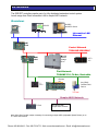
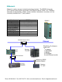
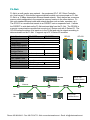
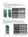
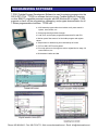
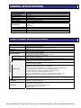
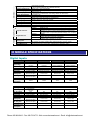
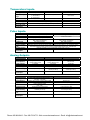
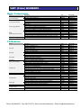
1
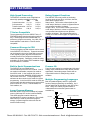
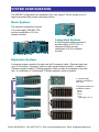
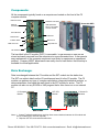
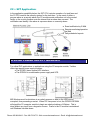
PROGRAMMABLE CONTROLLERS
S2E CPU
S2T CPU
100 Mb Ethernet
Toshiba Computer
Toshiba Automation
Phone: 800.894.0412 - Fax: 888.723.4773 - Web: www.ctiautomation.net - Email: [email protected]
V-Series S2E/S2T
Small, Powerful Modular Style
Programmable Controllers
Toshiba’s S2E/S2T controllers are small, modular type
programmable controllers suitable for simple relay
replacement all the way to complex control applications.
The S2E/S2T are 3rd generation T2 Series CPUs used with
V-Series racks, I/O, and power supplies. The S2E/S2T
provides a functional, economical, and compact solution to
a wide range of applications in automotive, machine control,
and process control systems.
S2E
Local I/O
Program
Speed
Station Bus
2048 Points
32 Ksteps
(Includes Comments)
0.11 µs/contact
0.65 µs/transfer
17.3 µs/floating point add.
No
S2T
Local I/O
Program
Speed
Station Bus
2048 Points
32/64 Ksteps
(Includes Comments)
0.09 µs/contact
0.54 µs/transfer
12.1µs/floating point add.
Yes
Phone: 800.894.0412 - Fax: 888.723.4773 - Web: www.ctiautomation.net - Email: [email protected]
KEY FEATURES
High Speed Processing
Debug Support Functions
The S2E/S2T controllers excel at applications
where high speed processing is required.
S2E
S2T
Contact Instruction: 0.11 µs
0.09 µs
Coil Instruction:
0.22 µs
0.18 µs
Transfer Instruction: 0.65 µs
0.54 µs
16-bit Addition:
1.08 µs
0.90 µs
The S2E/S2T offer many useful on-line debug
functions such as input force, coil force, data set,
status latch & sample trace.
Status Latch: This function collects (latches) the
on/off state of devices or values in registers when a
user specified condition is initiated.
Sample Trace: This function collects (records) the
on/off state of devices or values in registers over a
user specified interval when a user specified
condition is initiated. The collected data can be
viewed as a historical trend graph or exported as a
*.csv file.
T-Series Compatible
The programming tool for the S2E/S2T is the TPDS MS Windows based programming software.
Any T-Series program can be loaded and run
without any program conversion. Any HMI, OIS, or
Scada software used with the T-Series is also
compatible.
Comment Storage in CPU
The device/register tag and comment can be stored
in the S2E/S2T CPU memory. Tags and comments
can be viewed in the on-line mode without access
to the original program (tags and comments are
normally stored on the computer hard disk that
created the program). Debugging, trouble shooting
and editing is much simpler at the installation if tags
and comments are viewable.
Sample Trace Screen
Built-in Serial Communications
Process I/O
The S2E/S2T have an RS485 serial
communications port on the CPU module. One of
two modes is selectable; computer link mode or
free ASCII mode. In the computer link mode a
higher level controller, MMI/OIS, SCADA software
can connect to the CPU. T-PDS programming
software can also connect in this mode for remote
programming. In the free ASCII mode the CPU can
communicate with devices that have a simple ASCII
protocol such as T1 PLCs, Toshiba ASDs, bar
code readers, etc.
Fast 8 channel analog input modules and 4 channel
analog output modules solve many difficult process
applications. One analog output module has an
output hold function for safety during a down
condition
Large Program Memory
Both S2E & S2T CPUs have 32k steps of program
memory (64k step S2T version is also available).
This allows program creation without any
consideration for memory constraints. Non-volatile
flash memory is used for permanent program
storage. Important register values can also be
stored in flash memory.
Multiple Programming Languages
Both LD (ladder diagram) and SFC (sequential
function chart) programming are available. Up 11
lines of ladder can be included in each SFC action
block. Using SFC makes programs easier to
understand and it makes the system easier to
troubleshoot.
0
Step
Transition
Action in Individual Step
1
2
4
3
Phone: 800.894.0412 - Fax: 888.723.4773 - Web: www.ctiautomation.net - Email: [email protected]
SYSTEM CONFIGURATION
The S2E/S2T configurations are available from a very simple 3 I/O slot system to a to a
large local system with several networking options.
Basic System:
The simplest configuration consists
of a power supply, S2E/S2T CPU,
and any combination of 3 I/O or
network modules.
Integrated System:
A fully integrated system consists of
a power supply, an S2T CPU, a
computer module, and any
combination of 6 I/O or network
modules.
Expansion System:
A maximum system consists of a main rack and 3 expansion racks. Each rack can have
up to 8 I/O modules. Expansion racks can also accept network modules. In addition to
V-Series expansion racks, T2 Series expansion racks can also be connected to the main
rack. A combination of V-Series and T2 Series expansion racks is possible.
♦ A power supply
module is necessary in
each rack.
♦ Expansion cables are
available as follows:
30 cm,
50 cm,
70 cm,
1.5 m
. Max length = 4.5 m.
Phone: 800.894.0412 - Fax: 888.723.4773 - Web: www.ctiautomation.net - Email: [email protected]
SYSTEM COMPONENTS
A typical S2E/S2T system consists of a base rack with modules mounted on the rack.
From left to right modules are: Expansion Interface, Power Supply, CPU, and I/O
modules. If the rack supports the station bus, then a computer module or higher level
network module can be mounted following the CPU module.
S2E CPU Module
I/O Modules / Network Modules
Power Supply Module
Expansion I/O Interface
Base
Computer Link Port (RS485)
Programmer Port (RS232C)
COMPUTER MODULE
It is no surprise that Toshiba Corporation, a company well known for rugged laptop
computers, also has computer modules for its automation product line. The C2 module
is a Pentium III air cooled, fan-less computer designed for harsh industrial and process
environments. There are three models available:
Models:
Model No.
CPU
OS
Cache Memory
RAM Memory
HDD or
Opt Flash
Memory
IF: USB
Serial
PS2
LAN
Display
PC Card
RAS
Note:
GC2PU37ES
GC2PU37GS
GC3PU37HS
Mobile Pentium P3, 500 Mhz Processor
Windows 2000 Pro
Windows 2000 Pro
Windows XP Pro
Primary 32 Kb Secondary 256 Kb (CPU on die)
128 Mb
256 Mb
256 Mb
30 Gb
30 Gb
30 Gb
2 Gb
2 Gb
2 Gb
1 Ch. (Type A USB 1.0)
1 Ch. (Type A USB 1.0)
1 Ch. (Type A USB 1.0)
1 Ch. RS232C, 9 pin
1 Ch. RS232C, 9 pin
1 Ch. RS232C, 9 pin
1 Ch. Mouse, 1 Ch. Keyboard
1 Ch. Ethernet, 10 BaseT, 100 BaseTx, RJ45
1 Ch. RGB analog, 2 Mb RAM, 1600 x 1200, 65536 Colors
2 Slots, PCMCIA Type II
CPU Failure Detection (WDT), Thermal Failure Detection, Auto Shutdown on
Power Failure
Requires S2T CPU and rack with station bus.
Phone: 800.894.0412 - Fax: 888.723.4773 - Web: www.ctiautomation.net - Email: [email protected]
Components:
All the components typically found on a computer are located on the front of the C2
computer module.
RGB Connector
PCMPCA Card Slots
Ethernet
10/100 BaseTx
HDD (Hard Disk
Drive) is removable
on PU37 models
Removable HDD
LED Indicators
COM Port 1
Reset Switch
Mouse Port
Initialize Switch
Keyboard Port
USB Connector
DIP Switches
The hard disk in the C2 module (PU37) is removable. Hugh amounts of data can be
stored and easily removed from the computer at a more convenient time. It also permits
easy replacement of the computer component most likely to experience an operational
problem. Company MIS/IT departments can easily clone a hard disk so that a backup is
available for critical applications.
Data Exchange:
Data is exchanged between the C2 module and the S2T module via the station bus.
The S2T can collect data from the I/O modules and send it to the C2 module. The C2
module can perform any type of; complex calculations, diagnostic/statistical analysis, or
data manipulation, then send the result back to the S2T module for action. The C2
module can also run any SCADA or HMI program that is often times run on an external
PC.
C2 Computer
Module
S2T CPU
Module
Station Bus
V-Series I/O
Modules
I/O Bus
Notes: 1. Contact Toshiba for applications requiring direct communications between the C2 module and
the I/O modules (S2T CPU not required).
2. Requires S2T CPU and rack with station bus.
Phone: 800.894.0412 - Fax: 888.723.4773 - Web: www.ctiautomation.net - Email: [email protected]
C2 + S2T Application:
In the application possibility below, the S2T CPU controls operation of a tank farm and
the C2 CPU controls the security system for the tank farm. In the event of either a
process alarm or a security alarm, the C2 module sends notification out to the central
facility or the on-duty foreman over the internet that an alarm has occurred. The
notification can identify it the alarm is a process alarm or a security alarm.
♦ Event notification by E-Mail
♦ Remote monitoring/operation
via Web
♦ Daily scheduled reports.
SPECIAL POWER SUPPLY MODULES
For critical PLC applications or applications using the C2 computer module, Toshiba
offers two special power supply modules:
♦ The GPS691 has a special UPS interface.
♦ The GPS694 is a combination power supply and UPS.
MS Windows must be shutdown in an orderly manner or data on the HDD can be
corrupted, thus preventing a restart. When 120 Vac power is lost, the GPS691/GPS694
will signal the C2 computer module to begin an orderly shutdown of Widows. This is
done without any input from a keypad or mouse. Power to the C2 module is maintained
until Windows has shut-down.
Phone: 800.894.0412 - Fax: 888.723.4773 - Web: www.ctiautomation.net - Email: [email protected]
NETWORKS
The S2E/S2T controllers can be part of a fully distributed networked control system.
Levels range from Plant Information LAN to simple ASCII network.
Overview:
OIS-DS
with OPC Server
OIS-DS
PC
Information LAN
Ethernet
S2T
PLC
Control Network
TOSLINE S20/S20LP
∗MV300
Medium
Voltage
Drive
S2E
PLC
T2/T3
PLC
Field Network
TOSLINE F10, FL-Net, DeviceNet
Remote
I/O
T1
PLC
Any ODVA
Certified Field
Device
Simple ASCII Network
T1 PLC
Any Device with
simple ASCII Protocol
∗ An Active Star Coupler maybe necessary for connecting multiple ASDs (Adjustable Speed Drivers) on to
a Tosline S20 network.
Phone: 800.894.0412 - Fax: 888.723.4773 - Web: www.ctiautomation.net - Email: [email protected]
Ethernet:
Ethernet is used as an open industrial networking standard. The GEN651 allows the
S2T to access other devices connected on an Ethernet network. Either 10 or 100 Mbps
data rates can be selected. Cables, routers, switches, transceivers, converters, etc. are
commonly available from 3rd party vendors.
Order Number
Topology
Protocol
Transmission
Transmission Speed
Max No. of Stations
Max No. of
Modules/Station
Max Distance
Parameter Tool
Note
GEN651
Bus/Star
Ethernet TCP/UDP
Point-to-Point, Multicast, Broadcast
10 Mbps/100Mbps
256
4
GEN651
100m between stations/repeaters
EtherSetup_E Software
Standard Ethernet Switch
Existing
T3H PLC
S2T
PLC
Standard Ethernet Switch
Ethernet
EtherSetup_E software is
used to set:
♦ IP Address
♦ Subnet Mask
♦ Gateway
♦ Port Number
for each Ethernet module.
Ethernet to RS232
Interface Module
Existing
T2N PLC
Existing
T1 PLC
Phone: 800.894.0412 - Fax: 888.723.4773 - Web: www.ctiautomation.net - Email: [email protected]
Tosline S20/S20LP:
Tosline S20/S20LP is an N-to-N high-speed data link network. Implicit token passing
avoids the possibility of message collision. A Tosline S20/S20LP network is ideal for
real-time control between PLCs or between PLCs and Toshiba ASDs.
Tosline-S20LP
The Tosline-S20LP is a high-reliability
loop type fiber optic system. The doubleloop configuration and the floating master
function allow the Tosline-S20LP to
continue data link operation even if a
transmission cable is cut or a station
drops out of the network.
Tosline S20
The Tosline-S20 is a bus type data link
network. The transmission media can be
either co-axial or fiber optic cable
depending on the application
requirement. These station modules can
be mounted in any I/o slot, main, or
expansion rack, of a S2E/S2T system.
Order Number
GSN627**S (S2T)
GSN626**S ( S2T)
GSN622**S (S2E)
GSN625**S (S2T)
GSN621**S (S2E)
Topology
Transmission
Transmission
Speed
Max No. of
Stations
Max Distance
Double Optic Loop
Optic Bus
Scan/Broadcast
2 Mbps
Co-ax Bus
64
Scan Capacity
Scan Update Time
Service
Parameter Tool
Connectable
Devices
Note
SN622
SN626
30 km total, 1 km
10 km total, 1 km
1 km total.
between stations.
between stations.
4096 words.
1024 words.
1024 words.
61.4 ms/4096 words.
25 ms/1024 words.
25 ms/1024 words.
Scan Transmission & Message Transmission
Tosline SLS Software.
S2T, PCS, V1000.
S2E/S2T, PCS, ASD,
S2E/S2T, PCS, ASD,
MV300.
For Additional Details See TL-S20 & TL-S20LP User’s Manuals
SN621
SN625
Remote Programming/Monitoring is possible
through Tosline-S20/20LP
Tosline-S20/S20LP
S2E/S2T
S2E/S2T
T-PDS Programming
Software
Or
SLS Setup Software
Phone: 800.894.0412 - Fax: 888.723.4773 - Web: www.ctiautomation.net - Email: [email protected]
FL-Net:
FL-Net is a multi-vendor open network. Any equipment (PLC, NC, Robot Controller,
etc.) that has an FL-Net certified communications module can communicate on FL-Net.
FL-Net is a 10 Mbps deterministic Ethernet based network. Each station has a common
memory which sends data to the respective memory location in the other stations. FLNet uses standard Ethernet cable and network devices such as hubs, repeaters, etc).
The GFL612 is a module that mounts in an S2E/S2T main or expansion rack. It allows
the S2E/S2T to write data on the FL-Net and read data from the FL-Net. The GFL654 is
a remote communications module that mounts in a V-Series rack with V-Series I/O. The
GFL654 writes the status of its inputs on to the FL-Net and sets its outputs according to
data received from the FL-Net. It supports up to 32 V-Series I/O modules.
Order Number
Protocol
Topology
Transmission
Transmission Speed
Max No. of Stations
Max No. of
Modules/Station
Max Distance
Scan Capacity
Scan Update Time
Service
Parameter Tool
Conn. Devices
Note
GFL612**S
GFL612
GFL654**S
GFL654
Ethernet UDP/IP
Bus/Star
FL Control Network Ver. 2.0
10 Mbps
254
4
1
Per FL-Net Spec.
Per FL-Net Spec.
8 k words + 8 k bites
50 ms or less
FL-Net Message Transmission
S2E/S2T Program
Switches on Module
S2E/S2T, Any FL-Net certified device.
Not compatible with FL-Net Ver. 1.0
PLC
Remote
I/O
Any FL-Net
Certified Device
Ethernet
Remote
I/O
PLCs
Any FL-Net
Certified Device
Phone: 800.894.0412 - Fax: 888.723.4773 - Web: www.ctiautomation.net - Email: [email protected]
Tosline-F10:
Tosline- F10 is a field network suitable for small distributed I/O systems. It also allows
data link between S2E/S2T and older T-Series/EX-Series PLCs. Tosline-F10 is
extremely easy to setup and use compared to other field networks. There are two types
of Tosline-F10 modules available for the S2E/S2T CPUs.
♦ GUN611 Master Station
♦ GUN612 Remote Station
Model No.
GUN611**S & GUN612**S
Master Stn
Remote Stn
Topology
Bus
Access Method
Poling/Selecting
Trans. Speed
750 Kbps/250 Kbps
Max. Trans Dist.
750 Kbps: 0.5 Km
250 Kbps: 1.0 Km.
Max No. of Stns
32
Comm Service
Scan Transmission
Capacity
32 Words
Update Time
7 ms/32 words (750 Kbps)
12 ms/32 words (250 Kbps).
Conn. Devices
S2E/S2t, T1/T2/T3 PLCs.
Remote I/O Blks, ASD, etc.
Note:
For additional information see
Tosline-F10 User’s Manual
DeviceNet:
DeviceNet is an open field network. Many field devices (certified by ODVA) are
available from other manufactures to connect to DeviceNet. The DN611A is a Toshiba
DeviceNet scanner module for the S2E/S2T CPUs. The DN611A can read/write data to
any other manufacturer’s certified device; such as remote I/O blocks, manifolds valves,
sensors, ASDs, etc.
GDN611A
Model No.
Topology
Number of Slaves
Trans. Speed
Media Access
Modulation
Trans Dist. Thin
Thick
Max. Drop Length
Total Drop Length
Function
Number of DN611
Note:
GDN611A*S
Bus.
63 max.
125/250/500 Kbps.
CSMA/NBA
Base-band.
100 m
125k 250k 500k
500m 250m 100m
6m
6m
6m
156m 78m 39m
Bit Strop, Poll,
Limited by PS Capacity.
For Additional Information
see GDN611 User’s Manual.
Phone: 800.894.0412 - Fax: 888.723.4773 - Web: www.ctiautomation.net - Email: [email protected]
ASCII Networks
The S2E & S2T have two ports
that can be used for ASCII
communications, the RS232
programming port and the
RS485 serial port. Both ports
can function in the Computer
Link Mode. The RS485 serial
port can also function in the
Free ASCII mode.
Port.
Trans. Method
Trans. Speed
Framing
Protocol
Program RS232
Serial RS485
Half-duplex
9600 Bps
Start Bit: 1
Data Bits: 8
Parity: Odd/None
Stop Bit: 1
Computer Link
Programmer
Half-duplex
9600/19,200 Bps
Start Bit: 1
Data Bits: 7/8
Parity: Odd/Even/None
Stop Bit: 1/2
Computer Link
Free ASCII
Programmer
Programmer Port—Computer Link Mode
OIS
Operator Interface Station (like the
OIS60) connected directly to controller.
This leaves the RS485 port open for
remote connection by T-PDS
programming software, SCADA software
or other OISs’.
RS232
Serial Port—Computer Link Mode
RS485
Any higher level computer, cell
controller, or DCS having T-Series
protocol can read and write information
into the S2E & S2T controllers.
32 Stations Max
Serial Port—Free ASCII Mode
T1 PLCs setup in Computer Link Mode. Communication is possible to
any device (bar-code reader, weigh scale, etc) having a serial ASCII
communications mode (with fixed trailing code).
RS485
32 Stations Max
T1
PLC
Phone: 800.894.0412 - Fax: 888.723.4773 - Web: www.ctiautomation.net - Email: [email protected]
PROGRAMMING SOFTWARE
T-PDS (Toshiba-Program Development Software) is used for entering programs into the
S2E & S2T CPUs. T-PDS is a software that runs on any Toshiba Notebook Computer
or other IBM-PC compatible personal computer with MS Windows 95 or higher. T-PDS
supports on-line & off-line programming, debugging, and program documentation for all
T-Series programmable controllers. T-PDS has:
♦ A full-featured program editor that includes cut & paste search &
replace, insert, delete, etc.
♦ Group programming and block merger.
♦ Load, save, and compare programs between disk file and CPU.
♦ Monitor power flow status of on-line ladder program and register
values.
♦ Sample trace for determining time relationships of events.
♦ /O Force ON & OFF from keyboard.
♦ Print map options such as register values, register/device usage, full
cross-reference, etc.
♦ Built-modem initialize and dial.
Phone: 800.894.0412 - Fax: 888.723.4773 - Web: www.ctiautomation.net - Email: [email protected]
GENERAL SPECIFICATIONS
Item
Operation temperature
Storage temperature
Humidity
Dust
Atmosphere
Vibration immunity
Shock immunity
Noise immunity
Insulation resistance
Withstand voltage
Grounding
Cooling
Specification
0 to 55°C
-20 to 70°C
5 to 95%RH (no condensation)
3
10mg/m or less
No corrosive gas, no flammable gas
2
IEC61131-2 (10 to 150Hz, 9.8m/s )
2
IEC61131-2 (150m/s )
Power impulse: 1500Vp-p 1µs
ESD: 8kV
EMC directive
50MΩ or more (between external and internal circuits)
1500Vac for 1 minute
100Ω or less (type D grounding)
Natural air cooling
FUNCTIONAL SPECIFICATIONS
Item
Control Method
Processor
Station Bus
I/O Method
Number of I/O Points
Programming Language
Program Capacity
Application program
Memory
Instruction Set
Execution Speed
Scan System
Multi-Tasking
Specification
Stored program cyclic scan method
Overall control: 32-bit microprocessor
Instruction execution: Special designed language processor (LP)
S2T only.
Batch I/O (refresh with main task), direct I/O, or combination
1024 points (when 32 points I/O used)
2048 points (when 64 points I/O used)
Local I/O memory: 8192 bits/512 words (1 word = 16 bits)
Ladder diagram (relay symbol + function block)
Sequential Function Chart (SFC),
Steps: S2E=32K, S2T=32K (PU662T), S2T=64K (PU672T). Includes comments.
Main memory: SRAM (battery back-up)
Auxiliary memory: Flash memory (for program backup).
Basic ladder instructions: 24 types
Function instructions: 206 types
• Sequence (contact, coil, timer, counter, etc.)
• Data transfer (single word / double word, register table)
• Arithmetic (single word / double word, binary / BCD, signed / unsigned, floating-point)
• Logic operation (single word/double word, register table, bit table)
• Compare (single word / double word, signed / unsigned, floating-point)
• Program control (jump, For-Next, subroutine, SFC, etc.)
• Functions (limit, trigonometric, square root, integral, PID, function generator, etc.)
• Conversion (ASCII, BCD, 7-Seg, double word integer / floating-point real)
Others
S2E: 0.11µs / contact, 0.22µs / coil, 0.65µs / transfer, 1.08µs / addition, 17.3µs / floating-point mpl.
S2T: 0.09µs / contact, 0.18µs / coil, 0.54µs / transfer, 0.90µs / addition, 12.1µs / floating-point mpl
Floating scan or constant scan
(constant: 10 to 200ms, 10ms units)
1 Main program
4 Sub-program (1 initial task fixed)
1 Timer interrupt (interval: 1 to 1000ms, 1ms units)
8 I/O interrupt (task switch 500µs or less)
256 Subroutines
Phone: 800.894.0412 - Fax: 888.723.4773 - Web: www.ctiautomation.net - Email: [email protected]
I/O Relay/Register
User data
Auxiliary Relay/Register
Special Relay/Register
Timer Relay/Register
Counter Relay/Register
Data Register
Link Relay/Register
RAS
Comm Ports
Link Relay/Register
File Register
Index Register
Retentive Memory
Real-time Clock/Calendar
Computer Link Port
Programmer Port
Self-Diagnosis
Monitoring
Debug/Maintenance
8192 points / 512 words
(X/Y or XW/YW: batch I/O, I/O or IW/OW: direct I/O)
16000 points / 1000 words (R/RW)
4096 points / 256 words (S/SW)
1000 points (T./T)
(10ms timers or 100ms timers: user setting, default: 64 10ms timers)
512 points (C./C)
8192 words (D)
16000 points / 2048 words (Z/W) for TOSLINE-S20
(leading 1000 words: bit access possible)
4096 points / 256 words (L/LW) for TOSLINE-F10
32768 words (F), 512k additional for PU672T
3 words (I, J, K)
User specified range for RW, T, C, D, and whole F registers
Year, month, day, day of the week, hour, minute, second (battery back-up)
Interface
RS485 (4-wire)
Bit rate
300, 600, 1200, 2400, 4800, 9600, 19200 bps
Computer link mode: T-series computer link protocol (ASCII/binary)
Protocol
Free ASCII mode: non-procedure (desired message, max. 512 bytes)
Interface
RS232C
Bit rate
9600 bps (fixed)
T-series computer link protocol (ASCII/binary)
Protocol
(available ASCII command: ST, DR, DW)
Power interrupt check, battery voltage check, I/O bus check, I/O registration check,
I/O response, I/O parity, watchdog timer, illegal instruction, LP check, others
Event history record, scan time measurement, constant scan delay, others
On-line trace monitor, force function, sampling trace, status latch, others
I/O MODULE SPECIFICATIONS
Digital Inputs:
Item
Module type
Input voltage
Min. ON voltage
Max. OFF voltage
Input current
Input points
ON delay time
OFF delay time
Wire connection
Internal 5V power
consumption
Item
DI632D
Min. ON voltage
Max. OFF voltage
Input current
Input points
ON delay time
OFF delay time
Wire connection
Internal 5V power
consumption
IN653
IN663
AC input
100 to 120Vac,
+10/15% (50/60Hz)
80Vac
30Vac
7mA (at 100Vac)
16points (16/common)
200 to 240Vac,
+10/15%(50/60Hz)
160Vac
60Vac
6mA (at 200Vac)
16points (16/common)
20ms or less
20ms or less
15ms or less
15ms or less
Terminal block
Terminal block
100mA
100mA
15mA
15mA
DI633
DI634
DI635
DI635H
Module type
Input voltage
DI653
DC input, sink/source
12 to 24Vdc/ac,
100 to 110Vdc,
+10/-15%
+10/-15%
9.6V
84V
4.3V
22V
8mA (at 24Vdc)
2.3mA (at 100Vdc)
8 points (isolated)
16 points (8/common)
10ms or less (DC)
10ms or less
20ms or less (AC)
10ms or less (DC)
10ms or less
15ms or less (AC)
Terminal block
Terminal block
DC input, sink/source
12 to 24Vdc/ac,
+10/-15%
9.6V
3.6V
8mA (at 24Vdc)
16 points (16/common)
10ms or less (DC)
20ms or less (AC)
10ms or less (DC)
15ms or less (AC)
Terminal block
15mA
24Vdc, +10/-15%
24Vdc, +10/-15%
24Vdc, +10/-15%
16V
5V
4mA (at 24Vdc)
32 points (8/common)
16V
5V
4mA (at 24Vdc)
64 points (8/common)
16V
5V
4mA (at 24Vdc)
64 points (8/common)
10ms or less
10ms or less
1.0ms or less
15ms or less
15ms or less
1.5ms or less
Connector
Connector
Connector
70mA
100mA
100mA
Phone: 800.894.0412 - Fax: 888.723.4773 - Web: www.ctiautomation.net - Email: [email protected]
Digital Outputs:
Item
Module type
Output voltage
Load current
Output points
ON delay time
OFF delay time
Leakage current
Wire connection
Internal 5V power
consumption
DO633
DO635
DO633P
DC output, sink
5 to 24Vdc, ±10%
DO634
5 to 24Vdc, ±10%
DC output, source
12 to 24Vdc, +10/-5%
5 to 24Vdc, +10/-5%
1A/point (12/24V)
0.3A/point (5V)
1.2A/4 points
16 points (16/common)
1ms or less
1ms or less
0.1mA or less (24Vdc)
Terminal block
0.1A/point (12/24V)
0.05A/point (5V)
0.1A/point (12/24V)
0.05A/point (5V)
1A/point (12/24V)
1.2A/4 points
32 points (8/common)
1ms or less
1ms or less
0.1mA or less (24Vdc)
Connector
64 points (8/common)
1ms or less
1ms or less
0.1mA or less (24Vdc)
Connector
16 points (16/common)
1ms or less
1ms or less
0.1mA or less (24Vdc)
Terminal block
60mA
150mA
250mA
60mA
Item
Module type
Output voltage
Load current
Output points
ON delay time
OFF delay time
Leakage current
Wire connection
Internal 5V power
consumption
RO663
RO662S
AC663
Relay contact output, NO contact
24Vdc, +20% (max)
24Vdc, +20% (max)
240Vac, +10% (max)
240Vac, +10% (max)
2A/point (resistive load)
2A/point (resistive load)
8A/common
16 points (8/common)
8 points (isolated)
10ms or less
10ms or less
15ms or less
15ms or less
None
None
Terminal block
Terminal block
AC output
100 to 240Vac, +10/-15%
(50/60Hz)
0.5A/point
0.6A/2 points
12 points (4/common)
1ms or less
1/2 cycle + 1ms or less
1.2mA or less (at 100Vac)
3mA or less (at 240Vac)
Terminal block
80mA
40mA
300mA
Analog Inputs:
Item
AD624L
AD634L
AD624
AD674
0 to 10V
1 to 5V, 4 to 20mA
±10V
500kΩ or more
Voltage: 1MΩ or more
Current: 250Ω
1MΩ or more
Input channels
Resolution
Conversion cycle
1 to 5V, 4 to 20mA
Voltage: 500kΩ or
more
Current: 250Ω
4 channels
8 bit (0 to 250)
1ms/4 channels
4 channels
8 bit (0 to 250)
1ms/4 channels
Overall accuracy
±1%FS (0 to 55°C)
±1%FS (0 to 55°C)
4 channels
12 bit (0 to 4000)
2ms/4 channels
±0.5%FS (25°C)
±1%FS (0 to 55°C)
4 channels
12 bit (-2000 to 2000)
2ms/4 channels
±0.5%FS (25°C)
±1%FS (0 to 55°C)
Internal 5V power
consumption
50mA
50mA
50mA
50mA
Input signal
Input impedance
Item
AD628S
AD638S
AD668
Voltage: 500kΩ or more
Current: 250Ω
8 channels (isolated)
8 channels (isolated)
Resolution
12 bit (0 to 4000)
12 bit (-2000 to 2000)
Conversion cycle
2ms/8 channels
2ms/8 channels
Overall accuracy
±0.2%FS (25°C)
±1%FS (0 to 55°C)
±0.2%FS (25°C)
±1%FS (0 to 55°C)
±5V, ±10V, 0 to 5V, 0 to 10V,
1 to 5V, 0 to 20mA, 4 to 20mA
Voltage: 1MΩ or more
Current: 250Ω
8 channels
16 bit (-32000 to 32000)
(FS: ±10V)
1ms/channel
(8ms/8 channels)
±0.2%FS (25°C)
±0.5%FS (0 to 55°C)
Internal 5V power
consumption
600mA
600mA
300mA
Input signal
Input impedance
Input channels
0 to 5V, 0 to 20mA
±10V
500kΩ or more
Phone: 800.894.0412 - Fax: 888.723.4773 - Web: www.ctiautomation.net - Email: [email protected]
Temperature Inputs:
Item
Input signal
Temperature input
range
Input channels
Resolution
Conversion cycle
Overall accuracy
Internal 5V power
consumption
TC618
RT614
Thermocouple K, J, E
±100mV
K: -200 to 1200°C
J: -200 to 800°C
−
E: -200 to 600°C
7 channels (1ch for CJC)
8 channels
16 bit (-32000 to 32000)
16 bit (0.05°C/count)
1ms/channel (8ms/8 channel) (averaging available)
±0.2%FS (25°C), ±0.5%FS (0 to 55°C)
Pt100 (3-wire)
4 channels
12 bit (0.1°C/count)
200ms/4 channels
±0.3%FS (25°C)
300mA
500mA
-50 to 270°C
Pulse Inputs:
Item
Input channels
Input voltage
Input current
Input pulse rate
Counting rate
Count value
Counter operation
mode
Interrupt function
Internal 5V power
consumption
PI632
PI672
2 channels (phase A, B, M)
2 channels (phase A, B, M)
5/12/24V, ±5%
Conforms to RS422
15.5mA (5V), 15mA (12V), 12.5mA (24V)
Max. 100kpps (other than quadrature)
Max. 100kpps (other than quadrature)
Max. 50kpps (quadrature)
Max. 50kpps (quadrature)
Max. 200k count/sec
Max. 200k count/sec
24-bit binary (0 to 16777215)
24-bit binary (0 to 16777215)
Quadrature bi-pulse counter (90° phase shift), up/down counter (phase A = up / phase B = down),
auto-reset universal counter, speed counter, programmable interval timer, gate ON timer
Interrupt generation at count match with preset (main unit only)
500mA
650mA
Analog Outputs:
Item
DA622L
DA622
DA672
Overall accuracy
±1%FS (0 to 55°C)
1 to 5V, 4to 20mA
Voltage: 5kΩ or more
Current: 600Ω or less
2 channels
12 bit (0 to 4000)
1ms/2 channels
±0.5%FS (25°C)
±1%FS (0 to 55°C)
±10V
Output channels
Resolution
Conversion cycle
1 to 5V, 4to 20mA
Voltage: 5kΩ or more
Current: 600Ω or less
2 channels
8 bit (0 to 250)
1ms/2 channels
2 channels
12 bit (-2000 to 2000)
1ms/2 channels
±0.5%FS (25°C)
±1%FS (0 to 55°C)
Internal 5V power
consumption
70mA
170mA
170mA
Output signal
Load impedance
Item
Output signal
Load impedance
Output channels
Resolution
Conversion cycle
Overall accuracy
Output at PLC
error
Internal 5V power
consumption
DA664
5kΩ or more
DA624S
±5V, ±10V, 0 to 5V, 0 to 10V, 1 to 5V,
0 to 20mA, 4 to 20mA
Voltage: 1kΩ or more, current: 600Ω or less
4 channels
16 bit (-32000 to 32000)
(FS: ±10V)
1ms/channel (4ms/4 channels)
±0.2%FS (25°C)
±0.5%FS (0 to 55°C)
1ms/4 channel or less
±0.2%FS (25°C)
±0.5%FS (0 to 55°C)
−
Output hold or reset (selectable)
230mA
220mA
0 to 20mA
550Ω or less
4 channels (isolated)
16 bit (0 to 64000)
Phone: 800.894.0412 - Fax: 888.723.4773 - Web: www.ctiautomation.net - Email: [email protected]
Change Detect DC Input
Item
Input voltage
Min. ON voltage
Max. OFF voltage
Input current
Input points
ON delay time
OFF delay time
Interrupt function
CD633
12 to 24Vdc, +10/-15%
9.6V
3.6V
7mA (at 24Vdc)
16 points (16 points/ common)
1ms or less
1ms or less
Interrupt generation at input signal state changing* (main unit only)
* signal state changing: rising / falling / both (user setting)
Internal 5V power
consumption
200mA
Communication Interface
Item
CF611
Interface
Transmission
mode
Synchronizing
Protocol
Bit rate
Code
Message length
Connectable
device
Signal connection
Internal 5V power
consumption
RS232C, 1 port
Full duplex
Start-stop method (asynchronous)
Non-procedure (trailing code detection)
300, 600, 1200, 2400, 4800, 9600, 19200 bps
ASCII (7 or 8 bits)
Max. 320 byte
Computer, bar-code reader, display device, sensor, printer, or other serial ASCII devices
D-Sub 9-pin connector (female)
550mA
Position Control Outputs
Item
Number of axis
Control method
Axis control
Control units
Positioning range
Pulse output
speed
Pulse output
method
Pulse output
signal
Acc/dec system
Operation mode
Other functions
Internal 5V power
consumption
MC612
MC614
2 axis
Pulse train output
Pulse, mm, inch, degree, etc.
±9,999,999 (control units)
4 axis
Pulse train output
Each axis independent, 2 axis linear
interpolation, 2 axis circular interpolation
Pulse
-134,217,727 to +134,217,726
Max. 200kpps
Max. 1.3Mpps
CW/CCW or pulse + direction
CW/CCW or pulse + direction
Each axis independent, 2 axis linear interpolation
5 to 24Vdc (50mA),
RS422
Automatic trapezoidal
Zero return, Jog, fix feed, direct positioning,
point No operation, automatic stepping,
jog/position switch, interrupt positioning
Electric gear, over ride, position change,
back-rash compensation, teaching,
feed-back pulse input (for monitoring)
700mA
RS422
Automatic trapezoidal / automatic S curve
Zero return, Jog, direct positioning,
point No operation, automatic stepping,
pulsar input operation
Over ride, position change,
back-rash compensation, teaching
700mA
Phone: 800.894.0412 - Fax: 888.723.4773 - Web: www.ctiautomation.net - Email: [email protected]
PART (Order) NUMBERS
Basic Components:
Name
S2E CPU Module
S2T CPU Modules
C2 Computer Modules
Power Supply Modules
Base
(main/expansion common)
Expansion I/O interface
Description
32K steps, built-in RS485 port
32K steps, built-in RS485 port
64K steps, built-in RS485 port, 1 Mb Memory
P-III, 500 Mhz, 128 Mb RAM, 30 Gb HDD, Windows 2000 Pro
P-III, 500 Mhz, 256 Mb RAM, 30 Gb HDD, Windows 2000 Pro
P-III, 500 Mhz, 256 Mb RAM, 30 Gb HDD, Windows XP Pro
24Vdc Input
100 to 110 Vdc Input
100 to 240 Vac, w/UPS Interface Connection
100 to 240 Vac Input
100 to 240 Vac, w/Battery for Computer Module Shutdown
Base Rack for S2T/S2, 4 Station Bus Slots, no I/O slots. Not for S2E.
Base Rack for S2T/S2, 9 Slots (Up to 5 station bus slots). Not for S2E.
Base Rack for S2E, 3 I/O Slots/ Expansion Rack for S2T/S2, 4 I/O Slots.
Base Rack for S2E, 5 I/O Slots/ Expansion Rack for S2T/S2, 6 I/O Slots.
Base Rack for S2E, 7 I/O Slots/ Expansion Rack for S2T/S2, 8 I/O Slots.
Parallel I/O bus 1 line (main/expansion common)
Type
PU612E
PU662T
PU672T
C2PU37
C2PU37
C2PU37
PS632
PS652
PS691
PS693
PS694
BU643D
BU648E
BU664
BU666
BU668
IF661
Part Number
GPU612E*S
GPU662T*S
GPU672T*S
GC2PU37ES
GC2PU37GS
GC2PU37HS
GPS632**S
GPS652**S
GPS691**S
GPS693**S
GPS694**S
GBU643D*S
GBU648E*S
GBU664**S
GBU666**S
GBU668**S
GIF661**S
Description
8 points (isolated), 12-24Vdc/ac input
16 points, 12-24Vdc/ac input
32 points, 24Vdc input
64 points, 24Vdc input
64 points, 24Vdc input (high-speed)
16 points, 100-110Vdc input
16 points, 100-120Vac input
16 points, 200-240Vac input
16 points, 24Vdc output, 1A/point
16 points, 24Vdc output, 1A/point (current source)
32 points, 24Vdc output, 0.1A/point
64 points, 24Vdc output, 0.1A/point
12 points, 100-240Vac output, 0.5A/point
16 points, 240Vac/24Vdc output, 2A/point
8 points (isolated), 240Vac/24Vdc output, 2A/point
4 channels, 1-5V / 4-20mA, 8 bit
4 channels, 0-10V, 8 bit
4 channels, 1-5V / 4-20mA, 12 bit
4 channels, ±10V, 12 bit
8 channels, 0-5V / 1-5V / ±5V / ±10V / 0-20mA / 4-20mA, 16 bit
8 channels (isolated), 0-5V / 0-20mA, 12 bit
8 channels (isolated), ±10V, 12 bit
4 channels, Pt100 input, 12 bit
8 channels, K / J / E / ±100mV, 16 bit
2 channels, 1-5V / 4-20mA, 8 bit
2 channels, 1-5V / 4-20mA, 12 bit
2 channels, ±10V, 12 bit
4 channels, 0-5V / 1-5V / ±5V / ±10V / 0-20mA / 4-20mA, 16 bit
4 channels (isolated), 0-20mA, 16 bit (output hold available)
2 channels, 100kpps, 5/12/24Vdc (interrupt generation)
2 channels, 100kpps, RS422 (interrupt generation)
16 points, 12-24Vdc input (interrupt generation)
2 axis, pulse output, 200kpps, independent / linear interpolation
4 axis, pulse output, 1.3Mpps, independent / linear / circular interpolation
RS232C 1 port, ASCII non-procedure
Type
DI632D
DI633
DI634
DI635
DI635H
DI653
IN653
IN663
DO633
DO633P
DO634
DO635
AC663
RO663
RO662S
AD624L
AD634L
AD624
AD674
AD668
AD628S
AD638S
RT614
TC618
DA622L
DA622
DA672
DA664
DA624S
PI632
PI672
CD632
MC612
MC614
CF611
Part Number
GDI632D*S
GDI633**S
GDI634**S
GDI635**S
GDI635H*S
GDI653**S
GIN653**S
GIN663**S
GDO633**S
GDO633P*S
GDO634**S
GDO635**S
GAC663**S
GRO663**S
GRO662S*S
GAD624L*S
GAD634L*S
GAD624**S
GAD674**S
GAD668**S
GAD628S*S
GAD638S*S
GRT614**S
GTC618**S
GDA622L*S
GDA622**S
GDA672**S
GDA664**S
GDA624S*S
GPI632**S
GPI672**S
GCD632**S
GMC612**S
GMC614**S
GCF611**S
I/O Modules:
Name
DC Input
AC Input
DC Output
AC Output
Relay Contact Output
Analog Input
RTD Input
Thermocouple Input
Analog Output
Pulse Input
Change Detect DC Input
Position Control
Communication Interface
Phone: 800.894.0412 - Fax: 888.723.4773 - Web: www.ctiautomation.net - Email: [email protected]
Network Modules:
Name
Ethernet
FL-Net
TOSLINE-S20
DeviceNet
TOSLINE-F10
Description
Ethernet 10/100 BaseT, for S2T CPU only.
FL-Net controller station (Ver.2.0)
FL-Net remote I/O station (Ver.2.0)
TOSLINE-S20 co-axial bus (S2E)
TOSLINE-S20 co-axial bus (S2T)
TOSLINE-S20 optical bus (S2E)
TOSLINE-S20LP (loop) optical bus (S2T)
TOSLINE-S20DLP (double loop) optical bus (S2T)
Scanner module
Master station
Remote station
Type
EN651A
FL612
FL654
SN621
SN625
SN622
SN626
SN627
DN611A
UN611
UN612
Part Number
GEN651A*S
GFL612**S
GFL654**S
GSN621**S
GSN625**S
GSN622**S
GSN626**S
GSN627**S
GDN611A*S
GUN611**S
GUN612**S
Description
0.3m length
0.5m length
0.7m length
1.2m length
5m length
Type
CS6R3
CS6R5
CS6R7
CS6*1
CJ905
Part Number
GCS6R3*CS
GCS6R5*CS
GCS6R7*CS
GCS6*1*CS
TCJ905*CS
Description
Windows95/98/Me/NT/2000/XP (English), CD-ROM version
Windows95/98/Me/NT/2000/XP (English)
DeviceNet Wizard for TOSHIBA (English)
Windows98/Me/NT/2000 (English)
Type
TPDS32
S-LS
−
T-PSV
Part Number
TMW3CE2SS
SMW23E*SS
TDW33E2SS
TPV33E2SS
Description
Blank module for vacant slot
Spare lithium battery
Type
SP600
BT611
Part Number
GSP600A*S
GBT611*AS
Cables:
Name
I/O Expansion Cables
T-PDS Connection Cable
Support Software:
Name
Programming Tool
S20 Configuration Tool
DeviceNet Wizard
DDE Server
Miscellaneous:
Name
Vacant Slot Cover
Battery
Note: Type Number is often times the number found on a module. However the Part
Number is necessary for ordering a new/replacement module.
A
115
B
A
B
BU668/BU648E
402.5
417
135
137
135
95
EXTERNAL DIMENSIONS
C
BU666
295.5
309.5
BU664/BU643D
224.5
238.5
C
Terminal block
143
Connector
169
Units = mm
Phone: 800.894.0412 - Fax: 888.723.4773 - Web: www.ctiautomation.net - Email: [email protected]
QUALITY
Toshiba Corporation is a vertically integrated manufacturing company. Semiconductors
are the building blocks of all electrical and electronic equipment and Toshiba is one of
the leaders in semiconductor fabrication. Toshiba’s integration continues through
printed circuit board assembly and testing to complete finished products (notebook
computer, television, adjustable speed drive, X-ray machine, PLC, etc.)
Toshiba Corporation’s quality management
system in design, development and
manufacturing insure that all Toshiba
products meet or exceed the requirements
of Quality Management Standard ISO9001.
Phone: 800.894.0412 - Fax: 888.723.4773 - Web: www.ctiautomation.net - Email: [email protected]
OTHER TOSHIBA PRODUCTS
After choosing the V-Series PLC, please consider other high quality industrial products
from Toshiba Corporation and Toshiba International Corporation. All of these products
are designed for rugged industrial applications and can provide a worry free installation.
Phone: 800.894.0412 - Fax: 888.723.4773 - Web: www.ctiautomation.net - Email: [email protected]