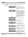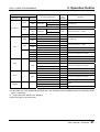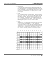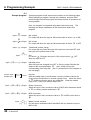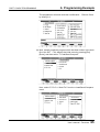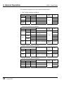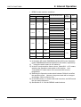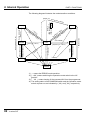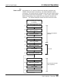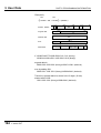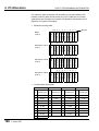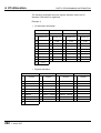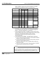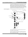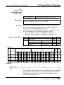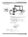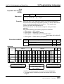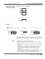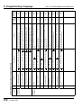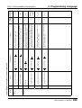
1
6F8C0928 Sequence Controller S2T User's Manual - Function - This manual is prepared for users of Toshiba’s Programmable Controller S2T. Read this manual thoroughly before using the S2T. Also, keep this manual and related manuals so that you can read them anytime while the S2T is in operation. General Information 1. The S2T has been designed and manufactured for use in an industrial environment. However, the S2T is not intended to be used for systems which may endanger human life. Consult Toshiba if you intend to use the S2T for a special application, such as transportation machines, medical apparatus, aviation and space systems, nuclear controls, submarine systems, etc. 2. The S2T has been manufactured under strict quality control. However, to keep safety of overall automated system, fail-safe systems should be considered outside the S2T. 3. In installation, wiring, operation and maintenance of the S2T, it is assumed that the users have general knowledge of industrial electric control systems. If this product is handled or operated improperly, electrical shock, fire or damage to this product could result. 4. This manual has been written for users who are familiar with Programmable Controllers and industrial control equipment. Contact Toshiba if you have any questions about this manual. 5. Sample programs and circuits described in this manual are provided for explaining the operations and applications of the S2T. You should test completely if you use them as a part of your application system. Hazard Classifications In this manual, the following two hazard classifications are used to explain the safety precautions. ! WARNING ! CAUTION Indicates a potentially hazardous situation which, if not avoided, could result in death or serious injury. Indicates a potentially hazardous situation which, if not avoided, may result in minor or moderate injury. It may also be used to alert against unsafe practices. Even a precaution is classified as CAUTION, it may cause serious results depending on the situation. Observe all the safety precautions described on this manual. Before reading this manual Safety Precautions Installation: ! CAUTION 1. Excess temperature, humidity, vibration, shocks, or dusty and corrosive gas environment can cause electrical shock, fire or malfunction. Install and use the S2T and in the environment described in the S2T User’s Manual - Hardware. 2. Improper installation directions or insufficient installation can cause fire or the units to drop. Install the S2T in accordance with the instructions described in the S2T User’s Manual - Hardware -. 3. Turn off power before installing or removing any units, modules or terminal blocks. Failure to do so can cause electrical shock or damage to the S2T and related equipment. 4. Entering wire scraps or other foreign debris into to the S2T and related equipment can cause fire or malfunction. Pay attention to prevent entering them into the S2T and related equipment during installation and wiring. Wiring: ! CAUTION 1. Turn off power before wiring to minimize the risk of electrical shock. 2. Exposed conductive parts of wire can cause electrical shock. Use crimp-style terminals with insulating sheath or insulating tape to cover the conductive parts. Also close the terminal covers securely on the terminal blocks when wiring has been completed. 3. Operation without grounding may cause electrical shock or malfunction. Connect the ground terminal on the S2T to the system ground. 4. Applying excess power voltage to the S2T can cause explosion or fire. Apply power of the specified ratings described in the S2T User’s Manual - Hardware. 5. Improper wiring can cause fire, electrical shock or malfunction. Observe local regulations on wiring and grounding. User’s manual - Functions 1 Before reading this manual Operation: ! WARNING 1. Configure emergency stop and safety interlocking circuits outside the S2T. Otherwise, malfunction of the S2T can cause injury or serious accidents. ! CAUTION 2. Operate the S2T and the related modules with closing the terminal covers. Keep hands away from terminals while power on, to avoid the risk of electrical shock. 3. When you attempt to perform force outputs, RUN/HALT controls, etc. during operation, carefully check for safety. 4. Turn on power to the S2T before turning on power to the loads. Failure to do so may cause unexpected behavior of the loads. 5. Set operation mode switches of the S2T and I/O modules. Improper switch settings may cause malfunction of the S2T and related equipment. 6. Do not use any modules of the S2T for the purpose other than specified. This can cause electrical shock or injury. 7. Configure the external circuit so that the external power required for output modules and power to the loads are switched on/off simultaneously. Also, turn off power to the loads before turning off power to the S2T. 8. Install fuses appropriate to the load current in the external circuits for the relay output modules. Failure to do so can cause fire in case of load over-current. 9. Check for proper connections on wires, connectors and modules. Insufficient contact can cause malfunction or damage to the S2T and related equipment. 10. Turn off power immediately if the S2T is emitting smoke or odor. Operation under such condition can cause fire or electrical shock. Also unauthorized repairing will cause fire or serious accidents. Do not attempt to repair. Contact Toshiba for repairing. 2 V series S2T Before reading this manual Maintenance: ! CAUTION 1. Do not charge, disassemble, dispose in a fire nor short-circuit the batteries, It can cause explosion or fire. Observe local regulations for disposal of them. 2. Turn off power before removing or replacing units, terminal blocks or wires. Failure to do so can cause electrical shock or damage to the S2T and related equipment. 3. Replace a blown fuse with a specified one. Failure to do so can cause fire or damage to the S2T. 4. Perform daily checks, periodical checks and cleaning to maintain the system in normal condition and to prevent unnecessary troubles. 5. Check by referring “Troubleshooting” section of the S2T User’s Manual - Hardware, when operating improperly. Contact Toshiba for repairing if the S2T or related equipment is failed. Toshiba will not guarantee proper operation nor safety for unauthorized repairing. 6. The contact reliability of the relays used in the relay output module will reduce if the switching exceeds the specified life. Replace the module if exceeded. 7. Replace the battery every 2 years to maintain the S2T’s program and data normally. 8. Do not modify the S2T and related equipment in hardware nor software. This can cause fire, electrical shock or injury. 9. Pay special attention for safety if you attempt to measure circuit voltage at the S2T’s terminal. 10. Turn off power before replacing modules. Failure to do so can cause electrical shock or damage to the S2T and related equipment. If you attempt to replace an I/O module while power on (by using on-line I/O replacement function), carefully check for safety. User’s manual - Functions 3 Before reading this manual Purpose of this manual Inside of this manual This manual describes the functions (those functions which can be achieved by the CPU and the basic hardware) of the Programmable Controller S2T. This manual also provides the necessary information for designing application programs and operating the S2T. Read this manual carefully to use the S2T with it’s maximum performance. This manual is divided into the following 3 Parts. Part 1. Basic Programming ............. Gives the basic information for programming, and shows how to write a program into the S2T with a simple example. Part 2. Functions............................. For the full understanding of the S2T functions, first explains the internal operation of the S2T CPU, and then explains the detailed functions of the S2T. Part 3. Programming Information .... Explains the information for designing a program which will fully use the functions of the S2T. Also explains Ladder diagram and SFC as programming languages for the S2T. Explains in the detailed information summarized in Part 1. Those who are using the S2T for the first time should first read Part 1 in order to understand the basics of programming. When Parts 2 and 3 are read in addition, the advanced control functions of the S2T will be understood without difficulty. Those experienced in using the S2T may skip Part 1, but refer to Parts 2 and 3 as necessary so as to fully use performance. An index is provided at the end of this manual for that purpose. When it comes to the configuration, some of the contents of Parts 1 and 3 are duplicated. However, please note that some portions of the explanation in Part 1 are summarized for ease of understanding. 4 V series S2T Before reading this manual Related manuals The following related manuals are available for the S2T. S2T User’s Manual-Hardware This manual covers the S2T’s main body and basic I/O-their specifications, handling, maintenance and services. S2T User’s Manual-Functions This document explains the functions of the S2T and how to use them. The necessary information to create user programs is covered in this volume. T-series Instruction Set This manual provides the detailed specifications of instructions for Toshiba’s T-series Programmable Controllers. T-PDS Basic Operation Manual This manual explains how to install the T-series program development system (T-PDS) into your personal computer and provides basic programming operations. T-PDS Command Reference Manual This manual explains all the commands of the T-series program development system (T-PDS) in detail. T-series Computer Link Function This manual explains the specification and handling method of the Tseries Programmable Controller’s Computer Link function. User’s manual - Functions 5 Before reading this manual Note and caution symbols Users of this manual should pay special attention to information preceded by the following symbols. Calls the reader’s attention to information considered important for full understandings of programming procedures and/or operation of the equipment. Calls the reader’s attention to conditions or practices that could damage the equipment or render it temporarily inoperative. Terminology 6 V series S2T AWG ASCII CPU EEPROM IF I/O LED ms NEMA PLC PS RAM ROM µs Vac Vdc American Wire Gage American Standard Code for Information Interchange Central Processing Unit Electrically Erasable Programmable Read Only Memory Interface Input/Output Light-Emitting Diode millisecond National Electrical Manufacture’s Association Programmable Controller Power Supply Random Access Memory Read Only Memory microsecond ac voltage dc voltage Contents PART 1 BASIC PROGRAMMING 1. Overview ...................................................................... 15 1.1 System design procedures ................................................... 15 1.2 Basic programming procedures ............................................ 16 2. Operation Outline........................................................ 19 2.1 Operation modes and functions ............................................ 19 2.2 Modes transition conditions .................................................. 20 2.3 Operation flow chart ............................................................. 22 3. I/O Allocation ............................................................... 24 3.1 I/O allocation ........................................................................ 24 3.2 Input and output registers ..................................................... 25 3.3 Rules for I/O allocation ......................................................... 27 3.4 Unit base address setting functions ...................................... 30 4. User Program .............................................................. 32 4.1 User program configuration .................................................. 32 4.2 System information............................................................... 33 4.3 User program ....................................................................... 34 4.4 Program execution sequence ............................................... 36 5. User Data ..................................................................... 37 5.1 User data types and functions .............................................. 37 5.2 Conditions for data initialization ............................................ 40 6. Programming Example ............................................... 41 6.1 Sample system..................................................................... 41 6.2 Input/output allocation .......................................................... 42 6.3 Sample program ................................................................... 44 6.4 Programming procedure ....................................................... 48 User’s manual - Functions 7 Contents PART 2 FUNCTIONS 1. Overview ......................................................................73 1.1 S2T System configuration..................................................... 73 1.2 Functional specifications....................................................... 74 2. Internal Operation........................................................75 2.1 Basic internal operation flow .............................................. 75 2.2 System initialization .............................................................. 76 2.3 Mode control......................................................................... 78 2.4 Scan control ......................................................................... 83 2.4.1 Scan mode ....................................................................... 85 2.4.2 Batch I/O processing ........................................................ 87 2.4.3 Timer update..................................................................... 89 2.5 Peripheral support ................................................................ 90 2.6 Programming support functions ............................................ 91 3. User Program Execution Control ...............................94 3.1 Program types ...................................................................... 94 3.2 Main/sub programs execution control ................................... 95 3.3 Interrupt programs execution control .................................. 102 4. Peripheral Memory Support Functions ...................104 4.1 Flash Memory (EEPROM) support ..................................... 104 4.2 Expansion memory support ................................................ 105 5. RAS Functions...........................................................106 5.1 Overview ............................................................................ 106 5.2 Self-diagnosis..................................................................... 106 5.3 Event history....................................................................... 110 5.4 Power interruption detection function.................................. 112 5.4.1 8 V series S2T Hot restart function ......................................................... 112 5.5 Execution status monitoring................................................ 113 5.6 Sampling trace function ...................................................... 114 5.7 Status latch function ........................................................... 119 Contents 5.8 Debug support function ...................................................... 120 5.8.1 Force function................................................................. 120 5.8.2 Online program changing function .................................. 120 5.8.3 DEBUG mode functions.................................................. 121 5.9 System diagnostics............................................................. 128 5.10 Password function .............................................................. 132 User’s manual - Functions 9 Contents PART 3 PROGRAMMING INFORMATION 10 V series S2T 1. Overview ....................................................................135 1.1 Aims of Part 3..................................................................... 135 1.2 User memory configuration................................................. 135 2. User Program Configuration ....................................137 2.1 Overview ............................................................................ 137 2.2 System information............................................................. 139 2.3 User program ..................................................................... 142 2.3.1 Main program ..................................................................... 143 2.3.2 Sub-program ...................................................................... 144 2.3.3 Interrupt program................................................................ 146 2.3.4 Sub-routines ....................................................................... 149 2.4 Comments .......................................................................... 151 3. User Data....................................................................152 3.1 Overview ............................................................................ 152 3.2 Registers and devices ........................................................ 155 3.3 Register data types............................................................. 180 3.4 Index modification............................................................... 187 3.5 Digit designation ................................................................. 191 4. I/O Allocation .............................................................196 4.1 Overview ............................................................................ 196 4.2 Methods of VO allocation.................................................... 197 4.3 Register and module correspondence ................................ 201 4.4 Network assignment ........................................................... 203 5. Programming Language ...........................................208 5.1 Overview ............................................................................ 208 5.2 Ladder diagram .................................................................. 211 5.3 SFC .................................................................................... 218 5.4 Programming precautions................................................... 233 Contents 5.5 5.5.1 Network support function .................................................... 235 Expand memory card data access through computer link .................................................................. 235 5.5.2 TOSLINE-S20LP (loop) support...................................... 238 5.5.3 Ethernet support ............................................................. 239 5.6 5.6.1 Double-word multiplication and division (D(/) .................. 241 5.6.2 Essential PID (PID3)....................................................... 243 5.6.3 Floating point essential PID (FPID3) ............................... 248 5.6.4 Expanded data transfer (XFER)...................................... 253 5.6.5 Network data send (SEND)............................................. 259 5.6.6 Network data receive (RECV) ......................................... 263 5.7 INDEX Instructions ......................................................................... 240 List of instructions............................................................... 267 ................................................................................................ 293 User’s manual - Functions 11 Contents 12 V series S2T PART 1 BASIC PROGRAMMING 1. Overview PART 1 BASIC PROGRAMMING 1.1 System design procedures Normally, the design of a control system to which the S2T is applied is carried out by the following procedure. System Planning Study the configuration of the control system and device configurations (including PLC selection). System Designing Thoroughly study the operation sequence of the system and the abnormal sequence. Detailed Designing Study the interfaces between S2T I/O modules and external devices, and determine the types of I/O modules. System Wiring Program Designing Create the S2T program according to the system operation sequence. Input/Output Operation Check Programming Enter the program by using the T-series programmer (T-PDS). Program Loading Load the program into the S2T. Debugging Carry out the S2T operation check by simulated inputs. Combination Test Carry out an operation check by combining with external devices (the power circuit should be cut off). Test Run Carry out system trial operation and adjustment. Program Storing Store the program on a disk file and make documentation. Hot Run User’s manual - Functions 15 1. Overview PART 1 BASIC PROGRAMMING 1.2 Basic programming procedures 16 V series S2T The basic procedures for creating a S2T program and loading the program into the S2T are as follows. (1) Determination of I/O Determine the types and arrangement of the I/O modules and make an input/output map for the external devices and the S2T’s data memory. (2) Program Designing Create the program based on the operation sequence of the system. At this time, give due consideration to constructing the program by dividing it into an input signal processing section, a control condition section and an output section. Also the program will follow the flow of control operation. By this means, the program should be easy to study, and therefore modification and additions should be simple. (3) Starting the T-PDS Start up the T-series Programmer (TPDS). (4) Selecting Offline Mode Set the T-PDS to Offline mode and initialize the Workfile (Workfile=Offline memory) (5) I/O Allocation Write the input/output allocation information based on the I/O allocation determined in (1) above. (6) Programming Write the program designed in (2) above into the disk. Do not forget the END instruction at the end of the program. (7) Start up the S2T Connect the S2T and the programmer (T-PDS) by the dedicated cable, and start the S2T with HALT mode. (8) Selecting Online Mode Set the T-PDS to Online mode. When communications between the S2T and the T-PDS are established, the S2T operation mode is displayed on the T-PDS screen. 1. Overview PART 1 BASIC PROGRAMMING (9) Clearing Memory Clear the S2T’s memory by issuing the Clear Memory command from the T-PDS. If the S2T is in ERROR mode, issue the Error Reset command, then issue the Clear Memory command. (10) Program Transfer Transfer the program created in offline mode to the S2T. (11) Program Debugging Put the S2T into RUN mode and check the operation. When the I/O modules are not all mounted, use the Forced RUN (RUN-F) function. (12) Program Modification Carry out any required modifications to the program. (13) Writing into the EEPROM (14) Normal Operation When the S2T CPU has built-in flash memory (PU662T/PU672T), write the program into the flash memory. Put the RAM/ROM switch to ROM, and the operation mode switch to RUN. Operation will then start automatically the next time when power is switched ON. The above procedure is called ‘Offline mode programming’. In the Offline mode programming, after the user program is developed without the S2T hardware, it will be loaded into the S2T at a time. User’s manual - Functions 17 1. Overview PART 1 BASIC PROGRAMMING On the other hand, the method of connecting the programmer (T-PDS) to the S2T and writing the program directly into the S2T is called ‘Online mode programming’. The procedure of Online mode programming is as follows. (1) Determination of I/O (2) Program Designing (3) Starting the T-PDS (7) Starting up the S2T (8) Selecting Online Mode (9) Clearing Memory Clear (initialize) the S2T’s memory. I/O Allocation When all the necessary I/O modules are mounted, the Automatic I/O Allocation function can be used. Programming Write the program directly into the S2T’s memory. (11) Program Debugging (12) Program Modification (13) Writing into the EEPROM (14) Normal Operation Set the T-PDS to Online mode. NOTE ▽▲▽ (1) Take special care for Safety during program debugging and test run. (2) If power is switched on when the RAM/ROM switch is in RAM, the S2T will not enter RUN mode automatically even if the Operation mode switch is in RUN. (See Section 2.2) 18 V series S2T 2. Operation Outline PART 1 BASIC PROGRAMMING 2.1 Operation modes and functions There are 3 modes of RUN, HALT and ERROR as basic operation modes of the S2T. Also, as a variation of the RUN mode, the RUN-F mode is available for debugging. RUN Mode: This is the program execution mode. The S2T repeats the reading of external inputs, execution of the user program and the determination of external output states. (One cycle of this operation is called a ‘scan’). Monitoring of the program execution state and forced input/output can be performed using the programmer. RUN-F Mode: This is a mode to force the program execution even when the I/O modules are not mounted. (In the normal RUN mode, this would give an I/O no answer error). This is used for program debugging. HALT Mode: This is the operation stop mode. The S2T switches OFF all outputs and stops user program execution. Normally, programming is carried out in this mode. Also, writing the program into the flash memory (in the case of the PU662T/PU672T) is available in this mode only. ERROR Mode: This is the ‘Error Down’ state. When the S2T detects an error by self-diagnosis which renders continuation of operation impossible, it will switch OFF all outputs, stop the use program execution and enter the ERROR mode. In the ERROR mode, all writing operations to the S2T are prohibited. In order to escape from this mode, it is necessary either execute ‘Error Reset’ from the programmer, or to switch the power supply OFF and ON again. NOTE ▽▲▽ 1. Programs can be changed in both the RUN mode and the RUNF mode (this is called the ‘online program changing function’). However, only normal programming in the HALT mode is described in Part 1. See Part 2 for the online program changing function. 2. Apart from the above 4 modes, there are actually the HOLD mode and the DEBUG mode as well. These are described in Part 2. User’s manual - Functions 19 2. Operation Outline 2.2 Modes transition conditions PART 1 BASIC PROGRAMMING To determine/change the operation mode of the S2T, the operation mode switch on the CPU module, programmer PLC control commands and S2T self-diagnosis are available. Also, the RAM/ROM switch on the CPU module controls the operation mode at power up. These are described below. * Operation Mode Switch...HALT/RUN Switch Position Operation Mode HALT When the mode switch is shifted from RUN or P-RUN to HALT, the operation mode will turn to the HALT mode. Also, when power is switched ON with the mode switch at HALT, the S2T will start up in the HALT mode. RUN When the mode switch is shifted from HALT to RUN, the operation mode will turn to the RUN mode. The mode when power is switched ON in the RUN position will be determined by the RAM/ROM switch. * Auto-RUN/Standby selection Switch Position Operation Mode Auto-RUN The S2T’s initial operation mode is determined by the mode control switch (HALT / RUN). When this switch is in RUN, the S2T moves into RUN mode automatically. Standby The S2T stays in HALT mode regardless of the mode control switch (HALT / RUN) after power on. Then the operation mode can be changed manually, i.e. by programmer command or by changing the mode control switch. * RAM/ROM switch: Switch Position Operation Mode RAM User program stored in RAM is used. (Program transfer from Flash Memory to RAM is not executed) ROM At the beginning of RUN mode, user program stored in flash memory is transferred to RAM. (It is called Initial load) * Mode control switch: Switch Position 20 V series S2T Operation Mode HALT User program execution is stopped. (HALT mode) Normally, programming is performed in the HALT mode. S2T operation mode control by programmer is not allowed. RUN S2T executes user program cyclically. (RUN mode) It is the normal switch position under operation. Even in the RUN mode, program changes are possible. However, saving into the flash memory is available only in the HALT mode. S2T operation mode control by programmer is possible. 2. Operation Outline PART 1 BASIC PROGRAMMING Previous state OP mode RAM/ROM RAM — (Power OFF) ROM — Mode SW HALT Power ON RUN Power ON HALT Power ON RUN Power ON — HALT RAM RUN HALT HALT ROM RUN RUN — HALT Auto-RUN RUN Standby HALT Auto-RUN Standby Error detection at power ON Command RUN RUN Command Force RUN Mode SW →RUN RUN Command RUN RUN Force RUN RUN-F HALT HALT HALT RUN HALT Error detection RUN — RUN — Initial Load execution → RUN Initial Load execution → RUN-F Mode unchange Command invalid (Mode unchange) ERROR Mode SW →HALT HALT Command HALT HALT Command RUN RUN Command Force RUN RUN Command invalid (Mode unchange) ERROR Mode SW →HALT HALT Command HALT HALT Command RUN RUN-F Command Force RUN RUN-F Error detection ERROR Mode SW (HALT/RUN) ERROR Command (except Error Reset) ERROR Command No Initial Load RUN-F Command (any) Error detection ERROR ERROR Command — — Initial Load execution → RUN RUN →HALT No Initial Load RUN →RUN Mode SW No Initial Load Initial Load execution Mode SW Command Remarks HALT RUN RUN RUN-F OP mode after transition HALT — RUN OP mode transition factor Error Reset HALT Command invalid (Mode unchange) Invalid Recovery to HALT mode 1) In this table, OP mode, RAM/ROM and Mode SW mean Operation mode, RAM/ROM switch and Operation Mode switch, respectively. 2) — means the switch status is not related to. 3) See next page for the Initial Load. User’s manual - Functions 21 2. Operation Outline 2.3 Operation flow chart PART 1 BASIC PROGRAMMING User programs can be produced without fully understanding the internal processes of the S2T. However, understanding the outline of the internal processes will be effective in producing more efficient programs and in carrying out appropriate debugging. The following drawing gives a S2T internal process overview. Power On Self-diagnosis (always) (ERROR mode) (HALT mode) System Initialization Initial Load ① User Data Initialization ② Operation Mode Control User program memory (RAM) Flash memory (RUN/RUN-F mode) ① ⑤ Batch Input Processing Program ③ [END] Data Batch Output Processing ② ④ Data ⑤ User Program Execution ⑤ Input Output ① ③ Input module ④ Output module ① Initial Load When the RAM/ROM switch is in ROM and the operation mode switch is in RUN, the following contents stored in the flash memory will be transferred to the S2T RAM at power up and at transiting from the HALT mode to the RUN mode. (1) Whole user program (2) Leading 4k words of data register (D0000 to D4095) 22 V series S2T 2. Operation Outline PART 1 BASIC PROGRAMMING ② User Data Initialization User data (data register, timer, counter, input register, output register, etc.) are initialized. User data is explained in Section 5. ③ Batch Input Processing The status of external input signals will be read from input modules and stored in the input registers. (The input register is sometimes called the ‘input image table’.) ④ Batch Output Processing The status of output registers is written to the output modules. The output module determines the ON/OFF state of output based on this. (The output register is sometimes called the ‘output image table’.) ⑤ User Program Execution The instructions stored in the user program memory are read one by one, and the contents of the output register are updated while referring to the contents of the user data. This is an essential function of the S2T. One cycle from operation mode control to user program execution is called ‘one scan’. The time required for 1 scan is called the ‘scan cycle’ (or the ‘scan time’). Generally, the shorter the scan cycle, the faster the output response to a change in input signal. NOTE ▽▲▽ The important items related to the S2T operation mode and the switches are summarized below. (1) When power is turned on with the RAM/ROM switch at RAM position, the S2T starts up in HALT mode. Therefore, use the RAM position during debug and test run, and set to ROM in normal operation, regardless of the type of the S2T CPU. (2) The object of the Initial Load is whole program and the leading 4k words of data register (D0000 to D4095). Therefore, even if the range of D0000 to D4095 is specified as retentive, these data will be initialized by the data of the flash memory. User’s manual - Functions 23 3. I/O Allocation 3.1 I/O allocation PART 1 BASIC PROGRAMMING As described in Section 2.3, communication between input modules or output modules and the user program is executed via the input registers and the output registers. I/O allocation is the determination of which address of the I/O registers shall be assigned to which I/O module. Basically, this is determined by the mounting order of the modules. Therefore, informing the CPU of the module mounting order is called ‘I/O allocation’. The following two methods are available for performing I/O allocation. Either method requires that the S2T is in the HALT mode and that the operation mode switch is in a position RUN. (1) Automatic I/O Allocation Execute the automatic I/O allocation command to the S2T from the programmer. The S2T CPU reads the module types of I/O modules mounted (see the table on the next page) and stores this in the user program memory as I/O allocation information. (2) Manual I/O Allocation Set the mounting positions and the module types of I/O modules on the I/O allocation screen of the programmer, and write this information to the S2T. Manual I/O allocation is used when performing programming in a state in which not all the I/O modules have been mounted, or when using the unit base address settings described in Section 3.4. Manual I/O allocation is also used for offline mode programming. When the I/O allocation information is stored in the S2T memory by these methods, the correspondence between the I/O modules and the I/O register is automatically determined by the rules described in Section 3.3. *) In practice, special allocation of module types other than those shown in the table on the next page can be executed by manual I/O allocation. However, the description is omitted here. The details are described in Part 3. 24 V series S2T 3. I/O Allocation PART 1 BASIC PROGRAMMING The module type of I/O module is expressed in the following table by a combination of a functional classification (X: lnput, Y: Output, X+Y: I/O mixed) and the number of registers occupied (W). Module DI632D/652 3.2 Input and output registers Description Module Type 8 points DC input X 1W DI633 16 points DC input X 1W DI634 32 points DC input X 2W DI635/635H 64 points DC input X 4W IN653/663 16 points AC input X 1W DO633/633P/653 16 points DC output Y 1W DO634 32 points DC output Y 2W DO635 64 points DC output Y 4W AC663 16 points AC output Y 1W RO663 16 points Relay output Y 2W RO662S 8 points Relay output (isolated) Y 1W AD624L/634L AD624/634 RT614 4 channels analog input X 4W AD668/TC618 8 channels analog input X 8W DA632L DA662/672 4 channels analog output Y 4W DA664 4 channels analog output Y 4W PI632 2 channels pulse input iX+Y 2W CF611 ASCII module iX+Y 4W SN621/622/625/626/627 TOSLINE-S20 data transmission TL-S UM611/612 TOSLINE-F10 data transmission TL-F In the previous Section, I/O allocation is the performance of correspondence between I/O modules and input/output registers. Here, the configurations of input registers and output registers, and methods of address expression are described. In descriptions hitherto, input registers and output registers have been treated as separate entities. However, from the viewpoint of memory configuration, this is not correct. User’s manual - Functions 25 3. I/O Allocation PART 1 BASIC PROGRAMMING In practice, the input register and the output register use the same memory area which is called the ‘I/O register’. In other words, before performing I/O allocation, the I/O register is not colour-divided for input and output. Colour-division of input and output in register units (16-bit units) is performed by carrying out I/O allocation. (Before allocation, internally, all are regarded as output registers). This idea can be conveyed by the following drawing. I/O Register (before I/O allocation) I/O Register (after I/O allocation) YW000 YW000 YW001 I/O allocation YW001 YW002 YW002 ... ... YW 255 YW255 Register contents (16-bit data) Register address Input/output classification (Input=XW, Output=YW) This address expresses allocation as output This address expresses allocation as input The I/O register is a 16-bit register, and 256 registers are available. (‘16-bit’ signifies that it stores the ON/OFF information for 16 points.) The I/O register used in the user program is expressed as follows. When an input register When an output register ...XW □□□ ...YW □□□ The above □□□expresses the register address (also called the ‘register number’), a decimal number from 000 to 255. Also, each bit (called a ‘device’) in the I/O register is expressed as follows. When a bit in an input register (input device) When a bit in an output register (output device) ★ ...X □□□□ ★ ...Y □□□□ ★ The above □□□expresses the register address and the □ expresses the bit position in the register. As bit positions, 16 positions of 0,1, ..., 9, A, B, C, D, E, F are available. 26 V series S2T 3. I/O Allocation PART 1 BASIC PROGRAMMING 3.3 Rules for I/O allocation When I/O allocation is performed either by the automatic I/O allocation or the manual I/O allocation method, the I/O allocation information (information on which type of module is mounted in which position) is produced in the user program memory. The coordination between the registers and the I/O modules is decided according to the following rules. (1) In the basic unit, allocation is carried out from the module immediately to the right of the CPU in sequence from the lowest register address. P S C X X X Y Y X X Y P 2 2 2 2 4 4 4 2 U W W W W W W W W XW000, XW001 XW002, XW003 XW004, XW005 YW006, YW007 YW008, YW009, YW010, YW011 YW020, YW021 XW016, XW017, XW018, XW019 XW012, XW013, XW014, XW015 (2) In the case of expansion units, allocations are given following on from the previous stage unit in sequence from the left end module to the right end module. Register allocation table Basic (#0) PU P C I F S P U 0 1 2 3 4 5 6 7 X X X Y Y X X Y 2 2 2 2 4 4 4 2 W W W W W W W W U n i t S l o Type t Register 0 0 X 2W XW000, XW001 7 Y 2W YW020 P Expansion I (#1) F S 0 1 2 3 4 5 6 7 X X X X Y Y Y Y 1 0 Y 2W XW022, XW023 2 2 2 2 2 2 1 1 W W W W W W W W 2 X 2W XW026, XW027 1 X 2W XW024, XW025 3 X 2W XW028, XW029 4 Y 2W XW030, XW031 P Expansion I (#2) F S 0 1 2 3 4 5 6 7 Y X X Y Y X X Y 2 2 2 2 2 2 2 2 W W W W W W W W 5 Y 2W XW032, XW033 6 Y 2W XW034 7 Y 2W XW035 2 0 Y 2W XW036, XW037 *) In the I/O allocation, for convenience, the module mounting position is expressed by a combination of the unit number and the slot number. Unit number: #0, #1, #2, #3 in sequence from the basic unit Slot number: 0,1, 2, ...7 in sequence from the module mounting position at the left end. User’s manual - Functions 27 3. I/O Allocation PART 1 BASIC PROGRAMMING (3) Slots in which no module is mounted (in manual I/O allocation, slots for which no type is set) do not occupy registers. These are called ‘vacant’ slots. P S C X X X P 2 2 2 U W W W V a c a n t V Y Y a c a 2 2 n W W t V a c a n t XW000, XW001 XW002, XW003 XW004, XW005 YW006, YW007 YW008, YW009 (4) In case of the 4-slot basic rack (BU643D), slots 4 to 7 are regarded as vacant. Similarly, in case of the 6-slot expansion rack (BU666), slots 6 to 7 are regarded as vacant. Basic (#0) PU P C I F S P U 0 1 2 X X Y 2 2 2 W W W 0 1 2 P X X X Expansion I (#1) F S 2 2 2 W W W 28 V series S2T 3 Y 2 W Register allocation table U n i t S l o t Type Register 0 0 X 2W XW000, XW001 1 X 2W XW002, XW003 2 Y 2W XW004, XW005 3 Vacant — 7 Vacant — 1 0 Y 2W XW006, XW007 1 X 2W XW008, XW009 2 X 2W XW010, XW011 3 X 2W XW012, XW013 4 Vacant — 7 Vacant — 3. I/O Allocation PART 1 BASIC PROGRAMMING (5) After an input/output register is allocated to an I/O module, the individual external signals on the module are allocated to each bit (device) on the register. At this time, in modules to which multiple registers are allocated, lower register address is allocated to the lower common (LC) side. (Example) The following is the input signal and input device coordination when XW004 and XW005 are allocated to a 32-point input module (X2W). X0041 1 X0043 3 X0045 5 X0047 7 X0048 8 X004A A X004C C X004E E LC1 PS PS X0051 1 X0053 3 X0055 5 X0057 7 X0058 8 X005A A X005C C X005E E HC1 NC 2 4 6 8 10 12 14 16 18 20 22 24 26 28 30 32 34 36 38 1 3 5 7 9 11 13 15 17 19 21 23 25 27 29 31 33 35 37 0 X0040 2 X0042 4 X0044 6 X0046 LC0 PS 9 X0049 B X004B D X004D F X004F 0 X0050 2 X0052 4 X0054 6 X0056 HC0 PS 9 X0059 B X005B D X005D F X005F NC (6) Special modules (modules which are not designated by X, Y, X+Y, iX, iY, iX+Y as module types) such as data transmission modules do not occupy input/output registers. (7) Input/output registers which are not allocated, internally become output registers, and can be used in the same way as auxiliary registers/relays in the program. User’s manual - Functions 29 3. I/O Allocation 3.4 Unit base address setting functions PART 1 BASIC PROGRAMMING As a special function for input/output allocation, there is a function which can set the base register address of each unit. This function is achieved by the manual I/O allocation. If this function is used, the register address does not shift even when module additions are carried out in the future. PU P C I F S P U Basic (#0) 0 1 2 3 4 5 6 7 X X X X X X X 4 4 4 2 2 2 2 W W W W W W W 0 1 2 3 4 5 6 7 Y Y Y Y Y Y Y P Expansion I (#1) F S 4 4 2 2 2 2 2 W W W W W W W P Expansion I (#2) F S PU 0 1 2 3 4 5 6 7 X X X X X X X 2 2 2 2 2 2 2 W W W W W W W 0 1 2 3 4 5 6 Y Y Y Y Y Y P Expansion I (#3) F S 7 2 2 1 1 1 1 W W W W W W Register allocation table U n i t Unit base address S l o t 0 00 PU Type 30 V series S2T S l o t Type — 2 60 0 X 2W XW060, XW061 Register X 4W XW000∼XW003 1 X 2W XW062, XW063 1 X 4W XW004∼XW007 2 X 2W XW064, XW065 2 X 4W XW008∼XW011 3 X 2W XW066, XW067 3 X 2W XW012, XW013 4 X 2W XW068, XW069 4 X 2W XW014, XW015 5 X 2W XW070, XW071 5 X 2W XW016, XW017 6 X 2W XW072, XW073 6 X 2W XW018, XW019 7 — 3 90 — 0 Y 2W YW090, YW091 0 Y 4W YW030∼YW033 1 Y 2W YW092, YW093 1 Y 4W YW034∼YW037 2 Y 1W YW094 2 Y 2W YW038, YW039 3 Y 1W YW095 3 Y 2W YW040, YW041 4 Y 1W YW096 4 Y 2W YW042, YW043 5 Y 1W YW097 5 Y 2W YW044, YW045 6 — 6 Y 2W YW046, YW047 7 — 7 30 Unit base address 0 7 1 Register U n i t — 3. I/O Allocation PART 1 BASIC PROGRAMMING NOTE ▽▲▽ (1) Apart from register address skipping between units, when the unit base address setting function is used, it follows the I/O allocation rules described in Section 3.3. (2) A setting which gives a latter stage unit a low register address cannot be performed. For example, a setting by which the base address of Unit #1 is 50 and the base address of Unit #2 is 30 cannot be performed. (3) When automatic I/O allocation is performed, there is no base address designation for any unit. The registers are allocated in succession. (As described in Section 3.3). User’s manual - Functions 31 4. User Program 4.1 User program configuration PART 1 BASIC PROGRAMMING A group of instructions for executing control is called a ‘user program’. This is also called an ‘application program’, a ‘sequence program’ or a ‘logic circuit’. In this manual it will be called a ‘user program’. The memory area which stores the user program is called the ‘user program memory’, and in the S2T it has a capacity of 32k steps. (PU662T)/64k steps (PU672T) However, out of this, 0.5k steps are used to store the user program ancillary information (this is called ‘system information’). Therefore, the actual user program capacity will be 31.5k/63.5k steps. Also, if Tags and Comments are stored in the S2T, a part of this area is used. A ‘step’ is the minimum unit which composes an instruction and, depending on the type of instruction, there will be 1-10 steps per instruction. Flash memory 0.5k steps System information 31.5k steps/ 63.5k steps User program RAM memory Tag and comment NOTE ▽▲▽ (1) For the conditions for transfer from the flash memory to the RAM (the Initial Load), see Section 2.3. (2) Tag and Comment are explained in Part 3. 32 V series S2T PART 1 BASIC PROGRAMMING 4.2 System information 4. User Program ‘System information’ is the area which stores execution control parameters and user program control information for executing the user program, and occupies 0.5k steps. The following contents are included in the system information. (1) Machine parameters (model type, memory capacity) (2) User program information (program ID, system comments, number of steps used, etc.) (3) Execution control parameters (scanning mode, sub-program and interrupt program execution conditions) (4) Retentive memory area information (5) I/O allocation information (6) I/O interrupt assignment information (7) Network assignment information (8) Computer link parameters (9) System diagnosis function execution conditions Out of these, the CPU automatically performs the setting/updating of the machine parameters of (1) and the number of steps used of (2). Items apart from these are set by the user from the programmer. Here, only the retentive memory area information of (4) and the I/O allocation information of (5) are described. The other items are described in Part 2 and Part 3. * Retentive memory area The ranges for retaining the data during power off can be set for the auxiliary register (RW), the timer register (T), the counter register (C) and the data register (D). Data other than within these set ranges will be 0-cleared (device is OFF) in the data initialization process at power up. This setting is performed in a way to designate from the first address (0) to a designated address for each of the above registers. (See Section 5.2 for details) * I/O allocation information As described in Section 3,I/O allocation information is stored here by executing automatic I/O allocation or manual I/O allocation. The CPU determines input/output register allocation based on this information. Also, as self-diagnosis, the CPU executes a check as to whether the modules in the allocation information are correctly mounted. User’s manual - Functions 33 4. User Program 4.3 User program PART 1 BASIC PROGRAMMING The user program is a group of instructions for executing control, and has a capacity of 31.5k/63.5k steps. The function which executes the user program is the main function of the programmable controller S2T. The user program is stored by each program type as shown in the following diagram, and it is managed by units called ‘blocks’ in each program type. Also, in 1 block, the user program is managed by a rung number (in the case of ladder diagram). Therefore, in the monitoring/editing the user program, a specified rung can be called by designating the program type, block number and rung number. User Program Configuration (Program Types) Program Type Internal Structure (Blocks) Block Internal Structure (Rung Numbers) Rung 1 Main program Block 1 Sub-program #1 Rung 2 Sub-program #2 MOV Block 2 Rung 3 Sub-program #3 Block 3 Sub-program #4 Timer interrupt program I/O interrupt program #1 I/O interrupt program #2 I/O interrupt program #3 I/O interrupt program #4 I/O interrupt program #5 I/O interrupt program #6 I/O interrupt program #7 I/O interrupt program #8 Sub-routine 34 V series S2T Block n (n=maximum 256) Rung m (m=no limit) 4. User Program PART 1 BASIC PROGRAMMING * Program Types As program types, the main program, sub-programs (#1-#4), the timer interrupt program, I/O interrupt programs (#1-#8) and the subroutines are available. Although there is a capacity limit of within a total of 31.5K/63.5k steps, there is no capacity limit on any of the program types. * Blocks From 1 to 256 are effective as block numbers. Every block has no capacity limit. In the S2T, apart from the Ladder diagram, the SEC language can be used. However multiple languages cannot be used in one block. In other words, when multiple languages are used, it is necessary to separate blocks. In the case of using the ladder diagram only, there is no need to divide the block. * Rungs Within the block, the user program is managed by the rung number. (In the case of the Ladder diagram). A ‘rung’ signifies one grouping which is linked by lines other than right and left power rails. There is no limit to the number of rungs which can be programmed within one block. The size of one rung is limited to 11 lines × 12 rows (maximum 132 steps), as shown in the following diagram. 1 2 3 4 5 6 7 8 9 10 11 12 1 2 3 4 5 6 7 8 9 10 11 User’s manual - Functions 35 4. User Program 4.4 Program execution sequence PART 1 BASIC PROGRAMMING The main program is the main body of the user program which executes every scan, and must have at least one END instruction. Here, the program execution sequence is described in the case of the main program only. The operation of other program types is described in Part 2. The user program is executed in the following sequence. ① The main program is .executed in sequence from the first block (the lowest number block) to the block which contains the END instruction. ② Within one block, it is executed in sequence from the first rung (Rung 1) to the last rung (in the case of the block containing the END instruction, to the rung which has the END instruction). ③ Within one rung, it is executed in accordance with the following rules. (1) When there is no vertical connection, execution is carried out from left to right. 1 2 3 (2) When there are OR connections the OR logic path is executed first. 1 2 4 4 6 7 3 5 (3) When there are branches, execution is carried out from the upper line to the lower line. 1 (4) A combination of (2) and (3) above. 1 3 2 2 3 4 5 6 7 4 5 6 8 7 NOTE ▽▲▽ 1. The block numbers need not be consecutive. In other words, there may be vacant blocks in the middle. 2. The rung numbers must be consecutive. In other words, vacant rungs cannot be programmed in the middle. 36 V series S2T 5. User Data PART 1 BASIC PROGRAMMING 5.1 User data types and functions Data stored in the RAM memory of the CPU and which can be referred directly in a user program, such as the states of input/output signals, control parameters and arithmetical results during execution of the user program are called ‘user data’. From the viewpoint of treatment, user data can be considered as divided into registers and devices. Registers are locations which store 16-bit data. The following types are available according to their functions. Code Name Function Number Address Range XW Input register Stores input data from the input module (batch input) YW Output register Stores output data to the output module (batch output) IW Direct input register Direct input data from the input module (direct input) OW Direct output register Direct output data to the output module(direct output) RW Auxiliary register Used as a temporary memory for results during execution of the user program 1000 words RW000-RW999 SW Special register Stores error flags, execution control flags, clock-calendar data timing clocks, etc. 256 words SW000-SW255 T Timer register Stores elapsed time during timer instruction execution 1000 words T000-T999 C Counter register Stores current count value during counter instruction execution 512 words C000-C511 D Data register Used for storing control parameters and as a temporary memory for execution results 8192 words D0000-D8191 W Link register Data exchange area with data transmission module (TOSLINE-S20) 2048 words W0000-W2047 LW Link relay register Data exchange area with data transmission module (TOSLINE-F10) 256 words LW000-LW255 File register Used for storing control parameters and for storing accumulated data 32768 words F0000-F32767 Index register Used for indirect addressing for register designation of instructions F I J K XW000-XW511 Total 512 words YW000-YW511 IW000-IW511 OW000-OW511 1 word I (No address) 1 word J (No address) 1 word K (No address) *1) In the S2T system, 1 word is treated as equal to 16 bits and units called words are used as numbers of registers. *2) All register addresses are decimal numbers. *3) In the timer register T000-T063 increase in 0.01 second units (0.01 second timer) and T064-T999 increase in 0.1 second units (0.1 second timer). User’s manual - Functions 37 5. User Data PART 1 BASIC PROGRAMMING On the other hand, ‘devices’ are locations which store 1-bit data (ON/OFF information). The following types are available according to their functions. Code Name Function Number Address Range Input device Stores input data from the input module (batch input) Corresponds to 1 bit in the XW register Y Output device Stores output data to the output module (batch output) Corresponds to 1 bit in the YW register I Direct input device Direct input data from the input module (direct input) I0000-I511F O Direct output device Direct output data to the output module (direct output) O000-O511F R Auxiliary relay device Used for internal relay. Corresponds to 1 bit in the RW register 16000 points R000-R999F S Special device Stores error flags, execution control flags, timing relays, etc. Corresponds to 1 bit in the SW register 4096 points S0000-S255F T. Timer relay device Reflects the execution result of the timer instruction Corresponds to the T register operation of the same address 1000 points T.000-T.999 C. Counter relay device Reflects the execution result of the counter instruction Corresponds to the C register operation of the same address 512 points C.000-C.511 Z Link device Data exchange area with data transmission module (TOSLINE-S20) Corresponds to 1 bit in the leading 512 words of the W register 16000 points Z0000-Z999F L Link relay device Data exchange area with data transmission module (TOSLINE-F10) 4096 points L0000-L255F X X0000-X511F Total 8192 points Y0000-Y511F The address expressions for devices are as shown below. Other than T. and C. ….X 063 F Bit position in the corresponding register (0-F) Address of corresponding register (decimal number) Function code (X, Y, O, I, R, S, Z, L) T. and C. ….T. 255 Address of corresponding register (decimal number) Function code (T., C.) 38 V series S2T 5. User Data PART 1 BASIC PROGRAMMING Therefore, for example, device X0352 expresses bit 2 of register XW035, and if X0352 is ON, it means that bit 2 of XW035 is 1. (MSB)* (LSB)* F E D C B A 9 8 7 6 5 4 3 2 1 0 XW053 Bit position 1 X0352=ON NOTE ▽▲▽ (1) The least significant bit (LSB) is bit 0 when numerical values are handled in the register. (2) When the direct input register/device (IW/I) are used in an instruction, input data will be read directly from the input module when that instruction is executed. (This system is called the ‘direct input system’). As opposed to this, in the input register (XW), input data will be read from the corresponding input module in a batch before user program execution. (This system is called the ‘batch input system’). In the input/output allocation. an IW and XW of the same address correspond to the same input module. (3) When the direct output register/device (OW/O) are used in an instruction, those data will be outputted directly to the output module when that instruction is executed. (This system is called the ‘direct output system’). As opposed to this, the contents of the output register (YW) will be outputted to the corresponding output module in a batch before user program execution. (This system is called the ‘batch output system’). In the input/output allocation, an OW and YW of the same address correspond to the same output module. Note that, in the case of direct output by device O, the other 15 bits in the same register (OW) are also directly outputted. (4) See Part 3 for details of registers/devices. * LSB : Least significant bit MSB: Most significant bit User’s manual - Functions 39 5. User Data 5.2 Conditions for data initialization PART 1 BASIC PROGRAMMING The user data are initialized according to the conditions in the following table at power up and at transiting the RUN mode. Also, the leading 4k words of the data register (D0000 to D4095), are the subjects of the Initial Load. Therefore, when the Initial Load conditions are established, initialization will be carried out in the sequence Initial Load → data initialization. (See Section 2.3 for Initial Load) Register/Device Initialization Input registers/devices (XW/X) For forced input devices the previous state is maintained, the others are 0-cleared. Output registers/devices (YW/Y) For coil forced output devices the previous state is maintained, the others are 0-cleared. Auxiliary registers/devices (RW/R) For registers designated as retentive and coil forced devices the previous state is maintained, the others are 0-cleared. Special registers/devices (SW/S) CPU setting part is initialized and the user setting part is maintained. Timer registers/relays (T/T.) Counter registers/relays (C/C.) For registers designated as retentive and the devices which correspond to them the previous state is maintained, the others are 0-cleared. Data registers (D) For registers designated as retentive the previous state is maintained, the others are 0-cleared. Link registers/relays (W/Z) For forced link devices the previous state is maintained, the others are 0-cleared. Link relays (LW/L) For forced link relays the previous state is maintained, the others are 0-cleared. File registers (F) All maintained Index registers (I,J,K) All 0-cleared *) The retentive memory area designation is available for the RW, T, C and D registers. These areas are designated by the system information setting function of the programmer. For each register the area from the first address (0) to the designated address becomes the retentive memory area. T-PDS’s Retentive Memory Area Designation Screen 13. Retentive memory area RW000 ∼ T000 ∼ C000 ∼ D0000 ∼ 40 V series S2T [ [ [ [ ] ] ] ] 6. Programming Example PART 1 BASIC PROGRAMMING 6.1 Sample system In this section, simple sequences as examples, input/output allocation, program designing and also the procedures for the actual programming operation are shown. Refer to them when using the S2T. Let us consider the sequence in the following diagram as an example 9 9 9 9 Numerical setting device (BCD output type) Operation switches (start, stop, emergency stop, fault reset) Limit switches (LS0, LS1, LS2, LS3) T3 Motor answerback (running forward, running in reverse) Motor (forward, reverse) Lamp displays (preparation complete, operating, operation complete, fault) Numerical display device (BCD input type) ① When the ‘Start’ switch is pressed with LS0 in the ON state, the following operation is executed. LS0 Foward LS1 Foward LS2 Foward LS3 (Stop for 1 second) (Stop for 2 seconds) (Stop for 3 seconds) (Stop for 10 seconds after LS0 returns to ON) Reverse ② The above operation is repeated only for the number of times set by the numerical setting device. During the operation, the ‘Operating’ lamp is lit and, at the same time, the actual number of executions at that time is displayed on the numerical display device. When the operation is completed, the ‘Operating’ lamp will go out, and the ‘Operation complete’ lamp will be lit. ③ If the ‘Stop’ switch is pressed during the operation, the motor is stopped at that position and, after 1 second, starts in reverse. When the LS0 becomes ON, the motor is stopped and, after 1 second, the ‘Preparation complete’ lamp is lit. User’s manual - Functions 41 6. Programming Example PART 1 BASIC PROGRAMMING ④ When LS0 is ON in states other than during operation, the ‘Preparation complete’ lamp is lit. The ‘Start’ switch is only effective when the ‘Preparation complete’ lamp is lit. ⑤ When the ‘Emergency stop’ switch has been pressed, the motor is stopped in that position and the ‘Fault’ lamp is lit. In that state, if the ‘Fault reset’ switch is pressed, the ‘Fault’ lamp will go out. 6.2 Input/output allocation First decide the module configuration and make a Map of Correspondence between external signals and registers/devices. Here, the allocation is made for modules with the configuration shown below. * Module configuration and register allocation 0 P S 6 9 3 1 2 P D D R U I O O 6 6 6 6 6 3 3 6 2 4 4 3 T 3 4 Rack : PS : CPU : Input : Output : BU643D (for Basic, 3 I/O slots) PS693 (100-120/200-240 Vac) PU662T (Standard) DI634 (32 points DC input) DO634 (32 points DC output) RO663 (16 points isolated Relay output) XW000, XW001 YW002, YW003 YW004 * Input/Output Map XW000 (Numerical Setting Device) X0000 01 ×100 02 03 04 05 ×101 06 07 08 09 ×102 0A 0B 0C 0D ×103 0E 0F 42 V series S2T X0010 11 12 13 14 15 16 17 18 19 1A 1B 1C 1D 1E 1F XW001 (Switches) Emergency stop (normally ON) Fault reset Start Stop LS0 LS1 LS2 LS3 Answerback forward Answerback reverse PART 1 BASIC PROGRAMMING 6. Programming Example YW002 (Numerical Display Device) YW003 (Lamps) Y0020 Y0030 Fault 21 31 Preparation complete ×100 22 32 Operating 23 33 Operation complete 24 34 25 35 ×101 26 36 27 37 28 38 29 39 ×102 2A 3A 2B 3B 2C 3C 2D 3D ×103 2E 3E 2F 3F YW004 (Motor) Y0040 Forward 41 Reverse 42 43 44 45 46 47 48 49 4A 4B 4C 4D 4E 4F User’s manual - Functions 43 6. Programming Example 6.3 Sample program PART 1 BASIC PROGRAMMING A sample program of this sequence are shown on the following pages. When designing a program, arrange the conditions, and give them careful thought so that the program will follow the flow of operations as far as possible. Here, the program is composed using basic instructions only. The following is a simple explanation of the instructions used in this program. A ○ Input —| |— Output NO contact A is ON. Put output ON when the input is ON and the state of device ○ A ○ Input —| |— Output NC contact A is OFF. Put output ON when the input is ON and the state of device ○ Input —|↑|— Output Transitional contact (rising) Put output ON only when the input at the previous scan was OFF and the input at the present scan is ON. A ○ Input —( )—| Coil A ON when the input is ON, and put device ○ A OFF Put device ○ when the input is OFF. A TON Tnnn ]— Output Input —[ ○ ON-delay timer After the input has changed from OFF to ON, put output ON after the A . Also, at this time put the elapse of the time specified by ○ corresponding timer relay ON. (the 0.1 second timer in the example on the next page) Counter input — A CNT — ○ Cnnn Output Enable input — Counter With the enable input in the ON state, count the number of times the count input is ON and store in counter register Cnnn. When the values A and Cnnn become equal, put output ON. When the enable of ○ input is OFF, clear Cnnn and put output OFF. A BIN ○ B ]— Output Input —[ ○ Binary conversion When the input is ON, convert the value of BCD which has been stored A to a binary number and store in ○ B . in ○ A BCD ○ B ]— Output Input —[ ○ BCD conversion A to BCD and is store in When the input is ON, convert the value of ○ B . ○ Input |—[ MCS ]—| |—[ MCR ]—| Master control set/reset Put the power rail between MCS and MCR ON only when the input of MCS is ON. 44 V series S2T 6. Programming Example PART 1 BASIC PROGRAMMING Operation Mode Setting Part 1 When ‘Emergency stop’ (X010: normally ON) is OFF, maintains Emergency R000 ON. R000 is reset by ‘Fault reset’ (X011) ON. stop X010 10 TON T064 1 second delay Emergency stop R000 X010 R000 ON delay timer is to wait the establishment of the emergency stop signal. Fault reset R000 R002 R003 R001 X018 2 Emergency Stop Operating LS0 stop R003 R016 X013 R000 ↑ 3 Stop Operating Stop Emergency complete stop R002 R001 X012 R014 R002 Preparation complete R002 When ‘operating’ (R003) is ON and ‘Stop’ (X013) is ON, the stop mode Stop (R002) is ON. When ‘Stop complete’ (R016) is ON, R002 is put to reset. R003 R000 ↑ 4 Start Preparation Operation Stop Emergency stop complete complete Operating R003 Operating Sequence R003 5 When ‘Preparation complete’ (R001) is ON and ‘Start’ (X012) is ON, the operation mode (R003) is put ON. When ‘Operation complete’ (R014) is ON, R003 is put to reset. When the operation mode (R003) is ON, the MCS-MCR is executed. MCS Operating 6 ↑ XW00 BIND D 5000 Numerical setting device R010 X019 7 ↑ R010 is put ON at the beginning of Running the operation. R010 is reset by forward LS1 (X019) being ON. When ‘Cycle complete’ (T.068) is ON also, in the same way, R010 is put ON. LS1 T.068 Cycle complete R010 X019 R013 8 LS1 Running in reverse T.065 X01A R011 When T.065 is ON, R011 is put ON Running and held. R011 is reset by LS2 forward (X01A) being ON. LS2 R011 X01A R013 LS2 Running in reverse T.065 is put ON after LS1 (X019) has been ON for 1 second. 10 TON T065 1 second delay 9 10 The value of the numerical setting device is binary-converted at the beginning of the operation, and is substituted in D5000. 20 TON T066 2 seconds delay T.066 is put ON after LS2 (X01A) has been ON for 2 seconds. User’s manual - Functions 45 6. Programming Example T.066 PART 1 BASIC PROGRAMMING R012 X01B 11 LS3 Running forward When T.066 is ON, R012 is put ON and held. When LS3 (X01B) is ON, R012 is reset. R012 X01B R013 T.067 is put ON after LS3 (X01B) has been ON for 3 seconds. 30 TON T067 12 Running reverse T.067 X018 LS3 3 seconds delay R013 13 LS0 Running in reverse When T.067 is ON, R013 is put ON and held. When LS0 (X018) is ON, R013 is reset. R013 X018 R010 ‘Cycle complete’ (T.068) is put ON after LS0 (X018) has been ON for 10 seconds. 100 TON T068 14 LS0 10 seconds delay Running forward R014 T.068 CNT 15 Cycle complete Operation complete The number of completed cycles are counted. When they equal the value (D5000) on the numerical setting device, ‘Operation complete’ (R014) is put ON. D5000 C000 16 17 Stop Sequence The count value (C000) is converted to BCD and is outputted to the numerical display. C000 BCD YW02 Numerical display MCR R002 MCS 18 Stop When the stop mode (R002) is ON, the MCS-MCR is executed. X018 19 LS0 10 TON T069 1 second delay R015 T.069 When LS0 (X018) is OFF, T.069 and R015 are put ON after 1 second. If LS0 (X018) is put ON, T.069 and R015 are reset. 20 Running in reverse R016 X018 21 LS0 22 46 V series S2T 10 TON T070 1 second delay Stop complete MCR ‘Stop complete’ (R016) is put ON after LS0 (X018) har 1 second. 6. Programming Example PART 1 BASIC PROGRAMMING Lamp Circuit R000 Y030 Emergency stop R001 Fault 23 Y031 When ‘Preparation complete’ Preparation (R001) is ON, the ‘Preparation complete complete’ lamp (Y031) is put ON. Y032 When ‘Operating’ (R003) is ON, Operating the ‘Operating’ lamp (Y032) is put ON. R017 R017 becomes ON immediately the operation mode (R003) or ‘Emergency stop’ (R000) is put ON. 24 Preparation complete R003 25 Operating R003 ↑ 26 When ‘Emergency stop’ (R000) is ON, the ‘Fault’ lamp (Y030) is put ON. Operating R000 Emergency stop R014 Y033 R017 When ‘Operation complete’ (R014) Operation is ON, the ‘Operation complete’ complete lamp (Y033) is put ON. When R017 is on, Y033 is reset. 27 Operation complete Y033 Motor Circuit R010 R000 X01D Running forward Emergency stop Running in reverse R000 X01C Y040 28 R011 Forward When R010, R011, or R012 is ON, ‘Forward’ (Y040) is put ON. This is interlocked by the ‘Running in reverse’ answerback (X01D). Running forward R012 R013 Y041 29 Running in Emerreverse gency stop R015 Running forward Reverse When R013 or R014 is ON, ‘Reverse’ (Y041) is put ON. This is interlocked by the ‘Running forward’ answerback (X01C). Running in reverse Program End 30 END User’s manual - Functions 47 6. Programming Example 6.4 Programming procedure PART 1 BASIC PROGRAMMING Here, the procedures for actually writing this program to the S2T using the programmer (T-PDS) are shown. (An operational example of TPDS version 2.0) (1) Turn the programmer power ON, startup the T-PDS by keying in TPDS [Enter). (T-PDS initial Menu Screen) In the initial state, the T-PDS starts up in the communication mode with the PLC (S2T). Therefore, in the state when it is not connected to the S2T, “Receive time-out” is displayed on the screen. (2) In order to carry out off-line programming, change to off line mode. Select “L: Online/Offline”, key-in L. 48 V series S2T 6. Programming Example PART 1 BASIC PROGRAMMING Here, select “F: Offline”. Key-in F. This sets the selection mode for the disk drive in which to create the off-line work file. Here, select “C: drive C” by keying-in C. The programmer is now waiting for confirmation the creation of a work file. Key-in Y. User’s manual - Functions 49 6. Programming Example PART 1 BASIC PROGRAMMING Next, the PLC model will be requested. Select “6: T3H” by keyingin 1. The T-PDS mode is changed to offline mode. “Offline C: ” is displayed at the bottom left of the screen. Since you are asked whether to record the settings, select “Y: Yes”. By this means, the next time the T-PDS starts up, it will start up with the work file in drive C as the target. 50 V series S2T PART 1 BASIC PROGRAMMING 6. Programming Example (3) Next carry out the I/O allocation. From the initial menu state, select “S: System information”. Key-in S. Here, select “A: I/O allocation information”. Key-in A. Then, key-in A to select “A: I/O allocation”. User’s manual - Functions 51 6. Programming Example PART 1 BASIC PROGRAMMING In offline programming, manual I/O allocation is carried out. Therefore, select F1 (Edit) on the command line. A cursor will appear on the screen. Because the module configuration has been decided in Section 6.2, carry out the following settings as the input/output allocation. ---- Unit #0 ---Slot I/O PU [ 0 [ X 2W 1 [ Y 2W 2 [ Y 1W ] ] ← DI634 (32 pts input) ] ← DO634 (32 pts output) ] ← RO663 (16 pts output) To set the module type, move the cursor to the specified slot position. Then designate by combining a function division (X, Y, etc.) and the number of the register occupied (1W, 2W, etc.) from the selection list displayed in the upper part of the screen. First, move the cursor to Unit #0, Slot 0, using the cursor keys. Then, key-in 1 to designate “1: X”. 52 V series S2T PART 1 BASIC PROGRAMMING 6. Programming Example Next, key-in B to designate “B: 2W”. “X 2W” is displayed as the module type at the bottom of the screen. Set the module type into the slot at the cursor position. Key-in [Enter]. “X 2W” is displayed at the Unit #0, Slot 0 position, and the cursor moves to the next slot. Hereafter, carry out the required settings using the same procedure. User’s manual - Functions 53 6. Programming Example PART 1 BASIC PROGRAMMING After completing required settings, write this information in the work file. Select F5 (Write) from the command line. The programmer will wait for confirmation. This completes the I/O allocation. 54 V series S2T Key-in Y. PART 1 BASIC PROGRAMMING 6. Programming Example (4) Now we enter the program typing phase. First, press the [Esc] key to return to the initial menu. The programmer will wait for confirmation. Key-in Y. Here, select “P: Program”. Key-in P. User’s manual - Functions 55 6. Programming Example PART 1 BASIC PROGRAMMING Block 1 of the main program is automatically selected, and “Block: M1” will be displayed on the screen. Here, select F1 (Menu) from the command line. Then, select “E: Program Edit” from the menu window and key-in E. A cursor will appear on the screen. Here, select F6 (Append) from the command line. Then, instruction symbols will appear on the command line. 56 V series S2T PART 1 BASIC PROGRAMMING 6. Programming Example Here, start typing in the program in Section 6.3. First, press F7 (TON). Since the programmer is waiting confirmation, key-in Y. Input the operands (setting value and timer register). Key-in 10 [Enter] T64 [Enter] If you make a mistake, cancel it with the Space key and re-input. User’s manual - Functions 57 6. Programming Example PART 1 BASIC PROGRAMMING Next, input the NC contact of X010 (with vertical connection). Key-in F2 ( —| |— ) F5 (I) X10 [Enter] Complete the 1st rung using the same procedure, as follows. Key-in F6 (—( )—| ) R0 [Enter] F1 (—| |— ) R0 [Enter] F2 (—| |— ) X11 [Enter] F4 (-) [Enter] F4 (-) [Enter] Next, move to the head of the 2nd rung using the cursor keys, and input the 2nd rung using the same procedure as for the 1st rung. Then input the 3rd and 4th rungs. 58 V series S2T PART 1 BASIC PROGRAMMING 6. Programming Example While doing this, when an instruction for which the symbol is not displayed on the command line such as a transitional contact, display the Menu Window by pressing Shift + F2 (Seq Inst), and then select. (Screen state when Shift + F2 (Seq Inst) has been pressed) When input has been completed as far as the 4th rung, write the 1st to 4th rungs into the work file. In other words, the size of program which is writable to the work file at any one time is one screen size (11 lines by 12 columns). Therefore, this means writing to the work file at convenient divisions of rungs. (The cursor also will move within the screen limits in the Edit mode). Carry out the operation of writing to the work file as follows: (State with input up to the 4th rung complete) User’s manual - Functions 59 6. Programming Example PART 1 BASIC PROGRAMMING Key-in Shift + F6 (Write). Because the programmer is awaiting confirmation, key-in Y. In this way, the 1st to 4th rungs have been written to the work file. Next, input the 5th rung onward. Move the cursor onto the 4th rung using the cursor keys (the cursor can move over existing rungs only), and press F6 (Append). The screen will then turn to an edit screen with the 4th rung leading. 60 V series S2T PART 1 BASIC PROGRAMMING 6. Programming Example Move the cursor to the head of the 5th rung, and start entering the program from there onward. To input the Function instructions such as BIN, key-in Shift + F3 (Fun Inst) to display Function instructions, then select the instruction group which contains the desired instruction. (Screen state when Shift + F3 (Fun Inst) has been pressed) (State when Shift + F3 (Convert) is pressed on the above screen) Hereafter, write the whole program using the same procedure. User’s manual - Functions 61 6. Programming Example PART 1 BASIC PROGRAMMING (5) When the whole program has been written in work file in the operation up to this point, load the program into the S2T. First, connect the S2T and the T-PDS with the dedicated cable. (This assumes that the modules in Section 6.2 are mounted in the S2T) Next, put the RAM/ROM switch on the CPU to RAM, the operation mode switch to the RUN position, and turn on power to the S2T. (The S2T will start up in the HALT mode) (6) Put the T-PDS into communication mode with the PLC (S2T). First, return the T-PDS display to the initial menu by pressing [Esc] [Enter], and then select “L: Online/Offline”. Here, select “N: Online” to select online mode. Key-in N. 62 V series S2T PART 1 BASIC PROGRAMMING 6. Programming Example Confirm the connection state and key-in Y When the communication of the T-PDS with the S2T is correctly connected, “PLC HALT” message will be displayed at the bottom left of the screen. Although the record of settings is not always required, here, select “Y: Yes”. Now the T-PDS has been changed to the online mode. User’s manual - Functions 63 6. Programming Example PART 1 BASIC PROGRAMMING (7) Next, clear the memory of the S2T. Select “S: System Information”. Key-in S. Here, select “M: Memory Management” from the <System Information> menu. Key-in M. Next, select “M: Clear Memory” from the <Memory Management> menu. Key-in M. 64 V series S2T PART 1 BASIC PROGRAMMING 6. Programming Example The programmer will await execution confirmation. Execute Clear by keying-in Y. (8) Next, transfer (load) the program which has been written in the work file to the S2T. First, display the initial menu by pressing [Esc] [Enter], and then select “T: Load/Save/Compare”. Here, select “P: PLC ↔ Work File” from the <Load/Save/Compare> menu. User’s manual - Functions 65 6. Programming Example PART 1 BASIC PROGRAMMING Then, select “L: Load (Work → PLC)” from the <PLC ↔ Work File> menu. The selection menu for loading details is displayed. Since it is simply the program in this example, select “P: Program & Sys Info”. The programmer will await execution confirmation. Key-in Y. When correct loading has been carried out “Complete” will be displayed. 66 V series S2T 6. Programming Example PART 1 BASIC PROGRAMMING (9) When the loading of the program has been completed by the above operations, operate the S2T (RUN mode) and debug the program. Here, try to change the S2T mode by the Control command of the T-PDS. First display the initial menu by pressing [Esc] [Enter], and then select “P: Program”. The T-PDS will enter the monitor mode for the program which has been loaded in the S2T. Here, select F9 (Control) from the command line. NOTE ▽▲▽ When the S2T is put into the RUN mode with the aim of program debugging and test running, take thorough precautions for safety, such as switching OFF the motive power circuit. User’s manual - Functions 67 6. Programming Example PART 1 BASIC PROGRAMMING Select “R: RUN” from the menu window. The programmer will await execution confirmation, key-in Y after rechecking the safety of the surroundings. “PLC: RUN” will be displayed on the screen. This is the monitor screen for the program execution state. Perform confirmation of operation by using the external simulation switch and the T-PDS simulation input function (Force function). For operation, see separate T-PDS operation manual. When carrying out program correction/modification, stop the S2T temporarily (put into the HALT mode), and correct/modify the program in the S2T. When carrying out creation/modification of the program while still in the online mode, the operations are the same as in to offline mode. 68 V series S2T 6. Programming Example PART 1 BASIC PROGRAMMING (10) When program correction and operation check are completed, save the program in the disk and switch OFF the S2T power. To finish with the T-PDS, press [Esc] [Enter] and select “Q: Quit” in the state with the initial menu displayed. The above completes the programming procedure. If the S2T’s RAM/ROM switch is put to ROM and the Operation Mode switch is put to RUN, the S2T will operate automatically when power is next switched ON. NOTE ▽▲▽ In the case of a CPU with a built-in flash memory, write the program into the flash memory before the above procedure (10). The operation can be performed by selecting “W: Program Write” from the <Memory Management> menu. (See the screen on the procedure (7)). User’s manual - Functions 69 6. Programming Example 70 V series S2T PART 1 BASIC PROGRAMMING PART 2 FUNCTIONS 1. Overview PART 2 FUNCTIONS 1.1 S2T System configuration The S2T system configuration is shown in the figure below. Part 2 explains the S2T system functions, concentrating on the S2T CPU functions. Serial I/F S2T TOSLINE-S20 3 or 8 modules Programmer (T-PDS) Basic unt P I C I S F P / U O (RS232C) … T I T L … L … / | O | S F Expansion cable Host computer Computer link (RS485) S2T S2T 41618 modules I P I F S / O ….. I / O I P I F S / O ….. I / O I P I F S / O ….. I / O Expansion unit (max. 3 units) TOSLINE-F10 T2E Remote I/O The internal block diagram of the S2T CPU is shown below. Flash Memory WDT Programmer Computer link RS232C B F Main processor RS485 RTC LSI Switches LEDs User program memory System RAM User data memory I F Language processor (I/O bus) I/O modules System ROM PF The Main processor controls overall execution tasks. The Language processor (LP) works as co-processor and executes the user program (bit operation and word operation). These two processors work in parallel during scan operation. User’s manual - Functions 73 1. Overview 1.2 Functional specifications PART 2 FUNCTIONS Item Control method Specification Stored program, cyclic scan system I/O method Batch I/O (refresh), Direct I/O, or combination Number of I/O points 1024 points (when 32 pts I/Os are used) 2048 points (when 64 pts I/Os are used) Total space: 8192 points/512 words Programming language SFC (Sequential Function Chart) Ladder diagram (relay symbol+function block) Program capacity 32k steps (PU662T) (incl. comment space) (1 step=24 bits) 64k steps (PU672T) Memory Main memory: SRAM (battery back up) Optional memory: Flash Memory Instructions Basic ladder instructions: 24, function instructions: 206 * transfer (single length/double length/register table) * arithmetic calculation (single length/double length/binary/BCD) * logical operation (single length/double length/register table/bit file) * comparison (single length/double length, sign/unsign) * program control (jump/FOR-NEXT/subroutine and others) * function (limit/trigonometric integral/PID/function generator) * conversion (ASCII/BCD/7 segment other) * Floating point operations Execution speed 0.1 µs/contact, 0.2 µs/coil 0.54 µs/transfer, 0.9 µs/addition User Program Scanning system Floating scan/constant scan (interval: 10-200 msec. 10 msec units) Multitasking 1 main program, 4 sub-programs 1 timer interrupt (1-1000 msec, 1 msec units), 8 I/O interrupt I/O device/register 8192 points/512 words (X/Y, XW/YW, batch I/O) (I/O, lW/OW direct I/O) Auxiliary device/register 16000 points/1000 words (R/RW) User data RAS 74 V series S2T Special device/register 4096 points/256 words (S/SW) Timer device/register 1000 points (T./T) (proportion of 0.1s and 0.01s timer is user definable) Counter device/register 512 points (C./C) Data register 8192 words (D) Link device/register 16000 points/2048 words (Z/W) (for TOSLINE-S20) Link relay/register 4096 points/256 words (L/LW) (for TOSLINE-F10) File register 8192 words (F) Index register I, J, K (total 3 words) Retentive memory User specified for RW, T, C and D Diagnosis Battery level, I/O bus check, I/O response, I/O registration, I/O parity, Watch dog timer, illegal instruction, LP check, others Monitoring Event history record, scantime measurement, others Debugging Online trace monitor, force, sampling trace, status latch, single step/N scan execution, break point, others 2. Internal Operation PART 2 FUNCTIONS 2.1 Basic internal operation flow The S2T basic operation flow chart is shown below. Power on System initialization Mode control HALT mode RUN mode Scan control Peripheral support Selfdiagnosis S2T performs system initialization following power on. If no abnormality is detected, S2T proceeds the mode control processing. Here, if the RUN mode transitional condition is fulfilled, the scan control begins. The scan control is the basic function of the S2T for the user program execution operation. And if the RUN mode transitional condition is not fulfilled, S2T enters the HALT mode and does not execute the user program. The peripheral support processing is executed as background for communicating with the programmer and the computer link. Self-diagnosis is carried out in each processing. The above figure shows the self diagnosis executed as background. The details of these processes are explained in this section. diagnosis is explained in 5 RAS functions. Self- User’s manual - Functions 75 2. Internal Operation 2.2 System initialization PART 2 FUNCTIONS The system initialization is performed after power is turned on. The following flow chart shows the sequence of processes explained below. ① CPU hardware check and initialization ② Power-off time, Power-on time record ③ Power interruption decision ④ Battery check ⑤ Initial load ⑥ User data initialization ⑦ User program check Time from power on to completion of the system initialization: Approx. 2 seconds (without initial load) Approx. 3 seconds (with initial load) ① CPU hardware check and initialization System ROM check, system RAM check and initial set up, peripheral LSI check and initial set up, RTC LSI check, and language processor (LP) check take place. ② Power-off time, Power-on time record The last time the power was switched off is recorded in the event history table, and the present date and time read from the RTC LSI is recorded as power-on time. Also the present date and time are set into the special register (SW007-SW013). ③ Power interruption decision In the hot restart mode (S0400 is ON), if power-off period is less than 2 seconds, it is decided as power interruption. In this case, initial load and user data initialization explained below will not be carried out. (only when the last power-off occurred in the RUN mode) ④ Battery check The battery voltage is checked for the user program and the user data backup. If the battery voltage is lower than the specified value a message is recorded in the event history table ‘batt voltage drop’ together with the special relay battery alarm flag (S000F) setting. 76 V series S2T 2. Internal Operation PART 2 FUNCTIONS ⑤ Initial load The initial load means the term for the transfer of the contents of the user program and the leading 4k words of the data register (D0000 to 04095), from the peripheral memory (Flash Memory) to the main memory (RAM), prior to running the user program. The initial load is initiated when the power is turned on, the operation mode switch is in RUN and the RAM/ROM switch is turned to ROM. * The initial load is not performed if the user program is written in the flash memory, but the contents are destroyed (BCC error detection). ⑥ User data initialization The user data (registers and devices) is initialized according to the conditions in the following table: Register/Device Initialization Input registers/devices(XW/X) For forced input devices, the previous state is maintained, the others are 0-cleared. Output registers/devices(YW/Y) For coil forced output devices, the previous state is maintained, the others are 0-cleared. Auxiliary registers/devices (RW/R) For registers designated as retentive and coil forced devices, the previous state is maintained, the others are 0-cleared. Special registers/devices (SW/S) CPU setting part is initialized and the user setting part is maintained. Timer registers/relays (T/T.) counter registers/relays (C/C.) For registers designated as retentive and the device corresponding to the previous state is maintained, the others are 0-cleared. Data registers (D) For registers designated as retentive, the previous state is maintained, the others are 0-cleared. Link registers/relays (W/Z) For forced link devices the previous state is maintained, the others are 0-cleared. Link relays (LW/L) For forced link relays, the previous state is maintained, the others are 0-cleared. File registers (F) All maintained Index registers (I, J K) All 0-cleared User’s manual - Functions 77 2. Internal Operation PART 2 FUNCTIONS *1) For the force function, refer to 5.11 Debug Support Function. *2) For the retentive memory area designation, refer to Part 3, Section 2.2. ⑦ User program check The contents of the user program on the main memory (RAM) are checked by BCC. 2.3 Mode control The S2T operation mode is selected according to the status of the operation mode switch on the CPU module and mode change requests from the peripherals (programmer, computer link, data transmission system). The S2T operation mode is basically divided into three; RUN mode, HALT mode and ERROR mode. Also, within the RUN mode, other than the usual RUN mode, RUN-F, HOLD and DEBUG modes mainly for debugging are also available. Operation mode switch HALT mode RUN mode Mode change according to commands from peripherals RUN-F mode RUN mode HOLD mode DEBUG mode Result of diagnosis 78 V series S2T ERROR mode 2. Internal Operation PART 2 FUNCTIONS The following explains the operation of each mode, after which the conditions (mode transition conditions) are explained. HALT: All external outputs are switched OFF, user program execution and I/O processing are halted. In the HALT mode the mode control is run periodically (every 50 ms), idle time is shared to peripheral support and diagnostic control. Externally this is the mode for creating/amending user programs. RUN: After initial load (where necessary), user data initialization (where necessary), I/O module mounting check, user program check, and scan mode decisions, S2T goes into the RUN mode. Mode control, batch I/O processing timer update, and user program execution are run repeatedly in the RUN mode. This is called scan control. There are 2 scanning methods; the floating scan repeats program execution continuously and the constant scan repeats program execution in a fixed cycle. Selection is called scan mode selection. Scan control is explained in detail in 2.4. RUN-F: This is the forced run mode. It differs from the above RUN mode in that scan control begins even if the allocated I/O modules are not actually mounted. (If other modules are mounted instead, the mode will not run.) Otherwise action is the same as the above RUN mode. HOLD: This is the scan temporary stop mode. Only the batch I/O processing is run, the timer update and the user program execution are halted. The scan mode continues from the status previously reached. The I/O module test can be performed by the data monitor/set function. DEBUG: This is the mode which may be used for program debugging functions (single step execution, single rung execution, N scan execution, breakpoint setting, etc.). In this mode, there are three sub-modes; D-HALT, D-STOP and D-RUN. For the DEBUG mode functions, see Section 5.11.3. ERROR: When an error is detected in one of the diagnostic checks and operation cannot be resumed by the prescribed retry action, S2T will enter this mode. In the ERROR mode the output is completely OFF, only the error reset command is effective from the programmer (the error reset command takes S2T back to the HALT mode). Refer to 5 RAS Functions for detailed diagnosis. User’s manual - Functions 79 2. Internal Operation PART 2 FUNCTIONS The transition conditions for each mode are shown below. • HALT mode transition conditions Previous state OP mode (Power off) • RAM/ROM Mode SW RAM — Power on ROM HALT Power on ERROR — — Command Other than above — RUN OP mode (Power off) IL, INZ Error Reset HALT Mode SW → HALT Command HALT HOLD OP mode transition factor OP mode after transition Note ROM RUN Power on RUN Power on (HOT restart) HALT Mode SW → RUN RUN Command HALT Mode SW → RUN IL, INZ RUN Command RUN IL, INZ RUN Command HOLD Cancel — ROM — IL, INZ RUN RUN INZ INZ RUN or RUN-F Return to mode before HOLD OP mode after transition Note RUN-F mode transition conditions Previous state OP mode HALT HOLD OP mode transition factor RAM/ROM Mode SW RAM RUN Command Force Run ROM RUN Command Force Run — RUN Command HOLD Cancel RUN-F INZ IL, INZ RUN or RUN-F Return to mode before HOLD OP mode after transition Note HOLD mode transition conditions Previous state OP mode transition factor OP mode RAM/ROM Mode SW RUN — — — RUN Command HOLD RUN Command HOLD RUN Command HOLD RUN-F D-RUN V series S2T INZ Mode SW HALT 80 Note RAM/ROM RAM • OP mode after transition RUN mode transition conditions Previous state • OP mode transition factor HOLD 2. Internal Operation PART 2 FUNCTIONS • DEBUG mode transition conditions Previous state OP mode transition factor OP mode RAM/ROM Mode SW HALT — — RUN Command Debug RUN Command D-HALT Command Initial Command Continue Command Step Command Rung Command Initial Command Continue Command Step Command Rung Command HOLD Cancel D-STOP D-HALT — D-STOP — HOLD — RUN RUN RUN OP mode after transition Note D-HALT INZ D-RUN INZ N scan complete Break point detected D-RUN — RUN Stop condition fulfilled Step execution completed D-STOP Rung execution completed Command D-HALT — RUN D-STOP — RUN D-RUN — RUN Mode SW Stop → HALT Command → HALT → HALT Command → HALT Mode SW → HALT Mode SW HALT *1) In the table, OP mode, RAM/ROM and Mode SW mean Operation mode, RAM/ROM switch and Operation mode switch, respectively. *2) — means the switch status is not related to. *3) In the OP mode transition factor column, “Mode SW → XX” means switching the Operation mode switch to XX position. And “Command XX” means issue of the command XX from the programmer. *4) Switching the Operation mode switch between RUN will not affect the operation mode. However, the protect state will be changed accordingly. (Refer to Section 5.4). *5) In the Note column, IL means initial load execution, and INZ means the user data initialization. *6) See Section 5.11.3 for the DEBUG mode functions. User’s manual - Functions 81 2. Internal Operation PART 2 FUNCTIONS The following diagram illustrates the mode transition conditions. (Power on) bu g」 or 「 ] RUN HA LT 」 [ RU N ]o RU r「 T AL ]o N」 L HA 「 r T」 H [ 「Force RUN」 HALT RUN-F HALT] or「HALT」 [ L HA T] [ HALT] or「HALT」 「HOLD」 [ 「Error Reset」 Break point detect, etc. [RUN 「HOLD」 D-RUN 「HOLD Cancel」 HA LT ] and 「HOLD」 「 De -RUN 「HOLD Cancel」 Debug command 「D-HALT」 [ D-STOP Debug command「xx」 Debug command「xx」 D-HALT (RAM) or (ROM) and [HALT] or (RAM) and Standby Auto HOLD 「HOLD Cancel」 ERROR *1) --- means the ERROR mode transition. *2) [ →XX ] means switching the Operation mode switch to the XX position. *3) 「 XX 」means issuing of the command XX from the programmer. *4) The setting status of the RAM/ROM switch and the Operation mode switch at power on are indicated by ( XX ) and [ XX ], respectively. 82 V series S2T 2. Internal Operation PART 2 FUNCTIONS 2.4 Scan control As explained in 2.3, when the RUN mode transition conditions are fulfilled, initial load (when necessary), user data initialization (when necessary), I/O mounting check, program check and scan mode setting are performed, and scan control begins. In scan control, mode control, batch I/O processing, timer update and user program execution are repeated. The following diagram shows the scan control flow chart. RUN mode transition conditions are fulfilled ① Initial load (when necessary) ② User data initialization (when necessary) ③ I/O mounting check ④ User program check ⑤ Scan mode setting ⑥ Batch I/O processing ⑦ Timer update ⑧ User program execution ⑨ Mode control ⑩ Batch I/O processing RUN mode transition process First scan Second scan and then after (repeated) ⑪ Timer update ⑫ User program execution User’s manual - Functions 83 2. Internal Operation PART 2 FUNCTIONS ① Initial load When the RAM/ROM switch is in the ROM side and the Operation mode switch is in the RUN position, the user program and the leading 4k words of the data register (D0000 to D4095) stored in the peripheral memory (flash memory) will be transferred to the main memory (RAM) in accordance with the following conditions. • Initial load will not be performed if the user program is written in the flash memory but the contents are destroyed (BCC error detection). In this case, the S2T will enter the ERROR mode. • Initial load will not be performed if the S2T is in the Hot restart mode from power interruption. ② User data initialization User data initialization takes place. Refer to 2.2, System initialization, for detailed initialization. User data initialization will not be performed if the S2T is in the Hot restart mode from power interruption. ③ I/O mounting check The I/O module mounting status is checked based on the I/O allocation information. (Refer to details in 5 RAS functions) ④ User program check BCC check will be performed on the user program in the main memory (RAM). (Refer to 5 RAS functions for details) ⑤ Scan mode setting Setting of the scan mode (floating scan or constant scan) will be performed. The scan mode is explained in 2.4.1. 84 V series S2T 2. Internal Operation PART 2 FUNCTIONS ⑥,⑩ Batch I/O processing Data exchange between the I/O image table (I/O register/device) and the I/O module will be performed based on the I/O allocation information. Data exchange with the data transmission module (TOSLINE-S20, TOSLINE-F10) will be also performed. The first scan is input only. Batch I/O processing is explained in 2.4.2. ⑦,⑪ Timer update The activated timer registers and the timing relays (S0040S0047) will be updated. Timer update is explained in 2.4.3. ⑧,⑫ User program execution User program instructions will be executed in sequence from the beginning to the END instruction. The execution object is a main program and sub-programs. In case of an interrupt program, when the interrupt is generated, the corresponding interrupt program is activated immediately. The user program execution control is explained in detail in section 3. ⑨ Mode control Will check the Operation mode switch and for mode change commands from the programmer and change the operation mode. Also, scan timing control will be performed by measuring the scan cycle. 2.4.1 Scan mode In the S2T, the scan mode enables select from floating scan and constant scan. The floating scan mode is that, immediately after one scan is complete the next scan commences. It is the shortest scan cycle but the scan cycle varies according to the user program execution state. The action of the floating scan is shown in the following diagram. Scan cycle … Mode I/O Timer User program Scan cycle Mode I/O Timer User program … Next scan begins immediately User’s manual - Functions 85 2. Internal Operation PART 2 FUNCTIONS The constant scan mode has a specified time cycle for scanning. The setup range of the cycle is 10-200 ms (10 ms units). Use this scan cycle to avoid variation in scan intervals. The action of the constant scan when the cycle is fixed at 50 ms is shown in the following diagram. Scan cycle (fixed at 50 ms) Mode I/O Timer User program Scan cycle (fixed at 50 ms) Mode I/O Timer User program … Scan mode selection will be performed by setting up the scan cycle in the system information menu of the programmer. To select floating scan, do not set up a scan time (leave blank). With the constant scan, scan time can be set up within the range 10-200 ms (10 ms units). NOTE ▽▲▽ In the constant scan, if the time for one scan exceeds a specified cycle, it will turn to floating scan, and the constant scan delay flag (special relay-S0008) comes ON. Also, when the scan time reverts to within the specified cycle, the scan cycle will return to the original constant scan. Constant scan cycle Mode I/O Timer Constant scan cycle User program Mode I/O Immediately to the next scan 86 V series S2T Timer User program Mode Returns to the constant scan 2. Internal Operation PART 2 FUNCTIONS 2.4.2 Batch I/O processing The status of the external input signals will be read from input modules onto the I/O register/device (XW/X). Output register/device (YW/Y) status will be output to the output modules. This process takes place before user program execution and is done in batches, hence named batch I/O processing. The object of the batch I/O processing is as follows: Batch input ... signals from input modules without i designation on I/O allocation and input registers/device (XW/X) which are not forced. Batch output ... output registers/devices (YW/Y) corresponding to output modules without i designation on I/O allocation. Also, data reading/writing between the data transmission module (TOSLINE-S20, TOSLINE-F10) and the link registers/relays (W/Z and LW/L) will be performed in this process. I/O register/device XW000 Input module XW001 YW002 YW003 Output module Link register/device Link register allocated to TOSLINE-S20 W0000 W0001 TOSLINE-S20 W0002 W0003 Link relay LW000 L0F … L01 L00 LW001 L1F … L11 L10 LW002 L2F … L21 L20 LW003 L3F … L31 L30 Link relay allocated to TOSLINE-F10 TOSLINE-F10 User’s manual - Functions 87 2. Internal Operation PART 2 FUNCTIONS If we consider S2T operation simply from the viewpoint of external signal exchanges, batch I/O processing and user program execution can be considered to be repeated continuously, as shown in the following diagram. Batch I/O processing Latest input data incorporated in XW YW data output externally Scan Running user program YW data updated with reference to XW data Basically, this has the advantage that high speed scanning is achieved because the S2T CPU does not access to the I/O modules during user program execution. Also it is easy to create program logic because the XW data are not changed during user program execution. This method is called the batch I/O processing method (refresh method). There is also another method of S2T operation whereby I/O module data exchange takes place during user program execution, using IW/I instead of XW/X, and OW/O instead of YW/Y. This method is called the direct I/O processing method. It is recommended that the I/O modules used in direct I/O are inhibited from batch I/O (they have i specification on I/O allocation) to shorten the time for batch I/O processing. NOTE ▽▲▽ (1) Use the following criteria for batch I/O processing time. Input (XW) ・・ 22 µs/register Output (YW) ・・ 22 µs/register Link (W/LW)) ・・ 7 µs/register (2) I/O modules with i designation on I/O allocation (iX, iY, iX+Y) are not part of batch I/O processing. Refer to Part 3 for I/O allocation. (3) Forced input devices (X), link register devices (Z), and link relays (L) are not part of batch I/O processing. The force function is explained in section 5.11.1. (4) Refer to the data transmission module manual for the allocation of the link register/relay (W/Z and L/LW) to the data transmission module. (5) With direct I/O processing, output will be in register units even when the bit (O) is specified. Refer to Part 3 for direct I/O registers. 88 V series S2T 2. Internal Operation PART 2 FUNCTIONS 2.4.3 Timer update The timer registers activated by timer instructions will be updated (increased), and the timing relays (S0040-S0047) will be updated. • Updating timer registers 10 msec system interrupt Scan Timer Timer Scan cycle Timer Scan cycle Timer update cycle Timer update cycle The number of system interrupts which occur during the timer update cycle (≈ scan cycle) will be counted, and the counts will be added up in the timer registers which are started up by the timer instructions (TON, TOF, SS, TRG). The 10 msec interrupt is used for the 0.01 second timer (T000-user), the 10 ms interrupts are accumulated and used for the 0.1 second timer (user-T999). The timer reset and the time-up processing will be performed in the execution of the timer instruction. Timer classification Timer register (Timer device) Preset range 0.01 second timer T000-T063 (T.000-user) 0-32767 (0 ∼ 327.67 seconds) 0.1 second timer T064-T999 (user-T.999) 0-32767 (0 ∼ 3276.7 seconds) Notes On-delay timer (TON) Off-delay timer (TOF) Single shot timer (SS) Timer trigger (TRG) *) Take the criteria for the time for performing the timer register update as follows. 4 µs/timer register (update time) • Updating timing relays The timing relays (S0040-S0047) ON/OFF status is controlled by using the 10 msec system interrupt. The binary counter is configured as shown on the next page. (When RUN is started up they will be all OFF) User’s manual - Functions 89 2. Internal Operation PART 2 FUNCTIONS S0040 (0.1 sec) S0041 (0.2 sec) S0042 (0.4 sec) S0043 (0.8 sec) 0.8 sec S0044 (1.0 sec) S0045 (2.0 sec) S0046 (4.0 sec) S0047 (8.0 sec) 2.5 Peripheral support 4.0 sec Peripheral support processing will interpret request commands from the peripherals (programmer, computer link, data transmission module), process the requests and responds. In the S2T, the Language processor (LP) takes charge of user program execution. The peripheral support processing will be performed by the main processor during user program execution in parallel. User program execution (LP) Scan control Mode User program I/O Mode . . . Timer Peripheral support *1) For commands which require accessing to user data, the command interpretation will be performed in parallel and the data accessing will be performed at the bottom of scan at batch for data synchronization. *2) If two or more commands are received simultaneously from the request sources, the order of priority will be as follows: Programmer > Computer link > TOSLINE-S20(CH1) > TOSLINE-S20(CH2) 90 V series S2T PART 2 FUNCTIONS 2.6 Programming support functions 2. Internal Operation The programming support functions are part of the functions realized as a result of peripheral support processing. Detailed programming support functions are explained in separate manuals for the programmer. The explanation here relates to an overview of the functions and their relation to the S2T operation modes. (1) Memory clear When the memory clear command is received, the content of the user program memory (RAM) will be initialized and the content of the user data memory (RAM) will be cleared to 0. (2) Automatic I/O allocation When the automatic I/O allocation command is received, the types of I/O modules mounted will be read and the I/O allocation information will be stored on the system information. (System information is in the user program memory.) (3) Reading the I/O allocation information The I/O allocation information will be read from the system information, and sent to the peripherals. (4) Writing I/O allocation information I/O allocation information received from peripherals is stored on the system information. (5) Reading the system information The system information (program ID, retentive memory specification, number of steps used, scan mode specification, other) is read and sent to the peripherals. (6) Writing system information The system information (user setup items) received from the peripherals is stored in the system information. (7) Reading the program In response to a request from peripherals, a specified range of instructions will be read from the user program memory, and sent to the peripherals. (8) Writing the program A specified range of instructions is received from peripherals and written onto the user program memory. After writing, the BCC (check code) correction will be carried out immediately. User’s manual - Functions 91 2. Internal Operation PART 2 FUNCTIONS (9) On-line program change Changing the content of the user program memory (adding/changing/inserting/deleting) and the BCC correction will be carried out in the RUN mode. This action is performed after completion of one scan, so the scan cycle is extended while this is being processed. Changing the program on-line is subject to the following restrictions. • You may not change the number or running order of instructions which are related to the program execution (see below). END, MCS, MCR, JOS, JCR, JUMP, LBL, FOR, NEXT, CALL, SUBR, RET, IRET • You may not change the SFC structure in the SFC program, but you may change the action corresponding to a step and a transition condition. (Ladder diagram part). (10) Batch reading of program The content of the user program memory (including the system information) is read and sent to the peripherals. It is used for the program uploading (S2T → Programmer → Disk). (11) Batch writing the program The user program (including the system information) is received from peripherals and will be stored in the user program memory. It is used for program download (Disk → Programmer → S2T). (12) Search The instruction/operand specified by peripherals will be searched through the user program memory and their address will be sent to peripherals. (13) Program check When the program check command is received, the user program syntax will be checked. The result of this check will be sent to peripherals. (14) Reading data The specified data will be read from the user data memory in response to a request from the peripherals, and the data will be sent to the peripherals. (15) Writing data User data address and data content received from peripherals will be stored in the user data memory. 92 V series S2T 2. Internal Operation PART 2 FUNCTIONS (16) Program reading from the EEPROM (flash memory). The checked the flash memory content will be transferred to the user program memory and user data memory (RW, T, C, D) of the main memory (RAM). (17) Program writing to EEPROM (flash memory). The content of the user program memory and the user data memory (RW, T, C, D) will be transferred to the flash memory. The execution conditions for these functions are shown in the following table. Function Execution conditions Reading I/O allocation information Reading system information Reading the program Always possible Reading data Batch reading the program Search Possible except in ERROR mode Program check Program writing to IC memory card/EEPROM Possible in HALT mode Memory clear Automatic I/O allocation Writing I/O allocation information Writing the system information Possible in the HALT mode Writing the program Batch writing the program Program reading from flash memory On-line program change Possible except in the ERROR mode Writing data Possible except in the ERROR mode NOTE ▽▲▽ If the password function is used, available functions are limited according to the protect level of the password. Refer to 5.13 for the password function. User’s manual - Functions 93 3. User Program Execution Control 3.1 Program types PART 2 FUNCTIONS The S2T can run several different program types in parallel (this function is called the multitask function). This function can be used to realize the optimal response time for each application. The programs are classified into the 3 types below. There are a total of 14 programs. • Main program (one) This program will be executed every scan and forms the main part of the scan. • Sub-programs (4) This program can be activated by other programs. A total of 4 (#1#4) are provided. (#1 is fixed function) In the floating scan, the sub-program will be executed after the main program execution with time limit (user setting). And in the constant scan, the sub-program will be executed in idle time from completion of the main program execution to the beginning of the next scan. By means of sub-programs, the main program can be used as fast scanning task, and the sub-programs as slow scanning (background) tasks. • Interrupt programs (9) When the interrupt condition is fulfilled, the S2T will stop other operations and execute the corresponding interrupt program immediately. A total of 5 are provided: one program which starts up at specified intervals (Timer interrupt program), and 8 programs which start up according to interrupt signals from I/O modules with an interrupt function (I/O interrupt programs #1-#8). By means of timer interrupt, time critical control can be achieved, and by means of I/O interrupts, I/O responses can take place without affecting the scan cycle. The sub-programs and the interrupt programs execution method and the execution conditions are explained in this section. 94 V series S2T 3. User Program Execution Control PART 2 FUNCTIONS 3.2 Main/sub programs execution control Four sub-programs (Sub#1 to Sub#4) can be registered. They will be executed according to the conditions described in the table below. Sub#1 will be executed only once before the main program execution in the first scan. The function of Sub#2 can be selected from the normal mode or special mode. Sub#3 and Sub#4 are fixed in normal mode function. In the normal mode, the execution mode can be selected from one time execution or cyclic execution. No. Sub#1 Normal/special N/A Normal mode when S0403=0 Sub#2 Special mode when S0403=1 Sub#3 Normal mode only Sub#4 Normal mode only One time/cyclic Operation N/A Executed only once before main program in the first scan. (after I/O processing) One time mode when 30405=0 Executed when S0409=1. S0409 is reset automatically. Cyclic mode when S0405=1 Executed once every specified scans (SW042) during S0409=1. N/A Executed only once before main program in the first scan, instead of Sub#1, if S0400=1 and the last power off period is less than 2s. One time mode when S0406=0 Executed when S040A=1. S040A is reset automatically. Cyclic mode when S0406=1 Executed once every specified scans (SW043) during S040A=1. One time mode when S0407=0 Executed when S040B=1. S0408 is reset automatically. Cyclic mode when S0407=1 Executed once every specified scans (SW044) during S0408=1. *) Hereafter, the main program, and sub-program #1 to sub-program #4 are referred as Main, Sub#1 to Sub#4, respectively. User’s manual - Functions 95 3. User Program Execution Control PART 2 FUNCTIONS The flags (special relays/registers) related to the sub-program operation are summarized in the table below. Sub No. Flag (Name) Sub#1 S0410 (Sub#1 executing) 0: Not executing 1: Executing Status Sub#2 S0400 (Hot restart mode) 0: Normal 1: Hot restart Setting S0403 (Special mode) 0: Normal 1: Special Setting S0405 (Sub#2 mode) 0: One time 1: Cyclic Setting S0409 (Sub#2 start) 0: No request 1: Start request SW042 (Sub#2 interval) Scan number setting for cyclic mode Setting S0411 (Sub#2 executing) 0: Not executing 1: Executing Status S0415 (Sub#2 delay) 0: Normal 1: Delay Status S0406 (Sub#3 mode) 0: One time 1: Cyclic Setting S040A (Sub#3 start) 0: No request 1: Start request Command SW043 (Sub#3 interval) Scan number setting for cyclic mode Setting S0412 (Sub#3 executing) 0: Not executing Status S0416 (Sub#3 delay) 0: Normal 1: Delay Status S0407 (Sub#4 mode) 0: One time 1: Cyclic Setting S040B (Sub#4 start) 0: No request 1: Start request Command SW044 (Sub#4 interval) Scan number setting for cyclic mode Setting S0413 (Sub#4 executing) 0: Not executing 1: Executing Status S0417 (Sub#4 delay) 0: Normal 1: Delay Status Sub#3 Sub#4 Function Note 1: Executing Command *) In the above table, “Setting” means the user preset flag for execution mode selection, “Command” means the user control flag for activating the sub-program, and “Status” means the execution status flag which can be monitored in the user program. Sub#1 operation Sub#1 will be executed only once in the first scan before Main execution. Therefore, Sub#1 can be used as the initial setting program at the start of the operation. HALT mode or system initialization First scan Mode Transition 96 V series S2T I/O Timer Second scan Sub#1 Main Mode I/O Timer Main PART 2 FUNCTIONS Sub#2 special mode operation 3. User Program Execution Control If Sub#2 is set as the special mode (S0403=1) and the Hot restart condition is fulfilled (S0400=1 and recovery from power off less than 2 sec), Sub#2 will be executed once in the first scan before Main execution. In this case, Sub#1 is not executed. Also, when the Hot restart condition is fulfilled, the initial load and the user data initialization will not be performed. Sub#2 special mode can be used as the initial setting program for the restart from power interruption. System initialization First scan Second scan (Hot restart) Mode Transition Normal mode operation (Sub#2, Sub#3, Sub#4) I/O Timer Sub#2 Main Mode I/O Timer Main In the normal mode, the sub-programs will be executed after the main program execution with time limit. The time assigned for the subprogram execution is different between in the floating scan mode and in the constant scan mode. In the floating scan mode: The user sets the sub-program execution time in the system information. The setting range is 1 to 100 ms (1 ms units). The activated sub-program(s) will be executed within this time limit. If the execution cannot finish within this time limit, the execution will be interrupted and re-started in the next scan. In the constant scan mode: The activated sub-program(s) will be executed in idle time from completion of the main program execution to the beginning of the next scan. If the sub-program execution cannot finish within this time limit, the execution will be interrupted and re-started in the next scan. There are two execution modes in the normal mode operation; the one time execution and the cyclic execution. In the one time mode, the sub-program will be activated when the Sub#n start flag changes from OFF to ON. In the cyclic mode, the sub-program will be cyclically activated every designated number of scans during the Sub#n start flag is ON. User’s manual - Functions 97 3. User Program Execution Control One time mode PART 2 FUNCTIONS The sub-program start request is checked at each time of the main program and the sub-program execution completed. If two or more start requests occur at a time, the order of priority will be as follows. Sub#2>Sub#3>Sub#4 When the sub-program is activated, the start flag is reset automatically. • Operation example in the floating scan Scan Scan Scan Scan Scan Main Sub#2 ⑤ (stopped) Sub#3 Sub#4 Time limit ④ ① ② ③ ⑥ ⑦ ⑧ ⑨⑩ ⑪ ⑫ ⑬ Sub#2 start (S0409) Sub#2 executing (S0411) Sub#3 start (S040A) Sub#3 executing (S0412) Sub#4 start (S040B) Sub#4 executing (S0413) ① Start requests to Sub#2, Sub#3 and Sub#4 from Main ② Sub#2 activated ③ Sub#2 completed and Sub#3 activated ④ Sub#3 interrupted and next scan started ⑤ Main completed and Sub#3 re-started ⑥ Sub#3 completed and Sub#4 activated ⑦ Sub#4 completed and next scan started ⑧ Start request to Sub#3 from Main ⑨ Sub#3 activated ⑩ Sub#3 completed and next scan started ⑪ Start request to Sub#2 from Main ⑫ Sub#2 activated ⑬ Sub#2 completed and next scan started 98 V series S2T 3. User Program Execution Control PART 2 FUNCTIONS • Operation example in the constant scan Scan (constant) Scan (constant) Scan (constant) Main Sub#2 Sub#3 ⑦ ⑧ (stopped) Sub#4 ① ② ③ ④ ⑤ ⑥ ⑨ Sub#2 start (S0409) Sub#2 executing (S0411) Sub#3 start (S040A) Sub#3 executing (S0412) Sub#4 start (S040B) Sub#4 executing (S0413) ① Start request to Sub#2 from Main ② Sub#2 activated ③ Sub#2 completed ④ Start requests to Sub#3 and Sub#4 from Main ⑤ Sub#3 activated ⑥ Sub#3 completed and Sub#4 activated ⑦ Sub#4 interrupted and next scan started ⑧ Sub#4 re-started ⑨ Sub#4 completed User’s manual - Functions 99 3. User Program Execution Control Cyclic mode PART 2 FUNCTIONS While the start flag is ON, the sub-program will be executed once every designated number of scans. The order of execution priority is as follows: Sub#2>Sub#3>Sub#4 The start flag should be controlled (ON/OFF) by the user program. If the sub-program execution cannot be completed within the designated scans, the delay flag (S0415, S0416, S0417) is set to ON. • Operation example in the floating scan n Scan counts n+1 n+2 n+8 n+3 n+20 Main Sub#2 (every 3 scans) ④ Sub#3 (every 8 scans) Sub#4 (every 20 scans) ⑤ (stopped) ① ② ③ ⑥ ⑦ ⑧ ⑨ ⑩ ⑪ Sub#2 start (S0409) Sub#2 executing (S0411) Sub#3 start (S040A) Sub#3 executing (S0412) Sub#4 start (S040B) Sub#4 executing (S0413) ① Start requests to Sub#2, Sub#3 and Sub#4 from Main ② Sub#2 activated ③ Sub#2 completed and Sub#3 activated ④ Sub#3 interrupted and next scan started ⑤ Sub#3 re-started ⑥ Sub#3 completed and Sub#4 activated ⑦ Sub#4 completed ⑧ Sub#2 activated in the first scan of next 3 scans ⑨ Sub#2 completed ⑩ Sub#3 activated in the first scan of next 8 scans ⑪ Sub#3 completed ⑫ Sub#4 activated in the first scan of next 20 scans ⑬ Sub#4 completed 100 V series S2T ⑫ ⑬ 3. User Program Execution Control PART 2 FUNCTIONS • Operation example in the constant scan (Sub#3 and Sub#4 are omitted) n+1 n Scan counts n+2 n+10 n+11 n+12 Main ③ Sub#2 (every 10 scans) ④⑤ (stopped) ① ② ⑥ ⑨ (stopped) ⑩⑪ (stopped) ⑦ ⑫ (stopped) ⑧ ⑬ Sub#2 start (S0409) Sub#2 executing (S0411) ① Start request to Sub#2 from Main ② Sub#2 activated ③ Sub#2 interrupted ④ Sub#2 re-started ⑤ Sub#2 interrupted ⑥ Sub#2 re-started ⑦ Sub#2 completed ⑧ Sub#2 activated in the first scan of the next 10 scans ⑨ Sub#2 interrupted ⑩ Sub#2 re-started ⑪ Sub#2 interrupted ⑫ Sub#2 re-started ⑬ Sub#2 completed User’s manual - Functions 101 3. User Program Execution Control 3.3 Interrupt programs execution control PART 2 FUNCTIONS When the interrupt condition is fulfilled, the S2T will stop other operations and execute the corresponding interrupt program immediately. As shown below, you can register one timer interrupt program which starts up according to an interval setup in system information and 8 I/O interrupt programs which start up according to interrupt signals from I/O modules with an interrupt function. Interrupt program Operation Timer interrupt Activated according to the interrupt interval setup in system information. The interrupt interval is set at 2 to 1000 ms (1 ms units) I/O interrupt #1 -I/O interrupt #8 I/O interrupt programs are activated by interrupt signals generated from I/O modules with interrupt function Set interval Set interval Interrupt conditions Timer Scan I/O #1 Scan Scan Timer I/O #4 Scan Scan Timer I/O #2 Scan Scan control Timer interrupt I/O interrupt #1 I/O interrupt #2 I/O interrupt #4 (1) Interrupt priority When several interrupt conditions occur simultaneously, the programs will be executed in the order of priority shown in the following table (the lower the numerical value the higher the level of priority). Also, if other interrupt conditions occur during an interrupt program execution the interrupt conditions will be put on hold, and after the interrupt program execution is completed, they will be executed in priority order. 102 V series S2T 3. User Program Execution Control PART 2 FUNCTIONS Interrupt program Timer interrupt Priority level Priority in class 0 — I/O interrupt #1 0 (initial value) I/O interrupt #2 1 (ditto) I/O interrupt #3 2 (ditto) I/O interrupt #4 I/O interrupt #5 1 3 (ditto) 4 (ditto) I/O interrupt #6 5 (ditto) I/O interrupt #7 6 (ditto) I/O interrupt #8 7 (ditto) The timer interrupt has the highest level of priority, followed by the I/O interrupt programs in order. With respect to the level of priority for I/O interrupt, the I/O interrupt from the module nearest the CPU has the highest level of priority. Refer to (3) below regarding the correspondence between interrupt programs and I/O modules. (2) Interrupt enable/disable You can switch between interrupt disable and enable by using the Dl instruction (interrupt disable) and El instruction (interrupt enable). By executing the Dl instruction, the interrupt conditions which occur during interrupt disable mode will be put on hold; these will be then executed instantly when the interrupt enable mode is entered by executing the El instruction. (DI and El should be used in a pair) Also, in transition to RUN mode, the interrupt will be disabled in the first scan. It will be enabled automatically from the second scan. (3) Allocation of I/O interrupt program The I/O interrupt with the lowest number corresponds to the I/O module with interrupt function nearest the CPU, in the initial state. This allocation can be changed. See Part 3 Section 2.3.3. There are no restrictions on the mounting position of I/O modules with the interrupt function. NOTE ▽▲▽ The I/O interrupt response time (from the time interrupt conditions arise until interrupt program starts up), with normal interrupt enable and no other interrupt program started up, is an instruction execution time +500 µs in worst case. User’s manual - Functions 103 4. Peripheral Memory Support Functions 4.1 Flash Memory (EEPROM) support PART 2 FUNCTIONS The contents of the user program and the register data can be stored in the flash memory. They can be read into the main memory (RAM) by the initial load function or programmer operation. Also, the data registers (D) stored in the flash memory can be accessed from the user program. Flash memory makes it possible to run without battery, and recovery is easy in the event of a program being destroyed. The following functions are available with EEPROM. Function Details Conditions Program write into flash memory Writes the contents of the user program (including the system information) and the data registers (D), the timer registers (T), the counter registers (C) and the auxiliary relay registers(RW) in the main memory (RAM) into the flash memory. Performed by the ‘Program write (RAM → IC card/ EEPROM)’ command from the programmer in the following state. - HALT mode Program read Transfers the contents of the flash from flash memory memory to the user program memory, the data registers (D), the timer registers (T), the counter registers (C), and the auxiliary relay registers (RW) in the main memory (RAM). Performed by the ‘Program read (RAM ← IC card/ EEPROM)’ command from the programmer in the following state. - HALT mode Initial load Transfers the contents of the flash memory to the user program memory and the leading 4 k words of the data registers (D0000 to D4095) in the main memory (RAM). At system initialization: - RAM/ROM switch is in ROM Reads the data of data registers in flash memory and stores in the main memory by user program. Writes the specified data of the main memory into the data registers in flash memory by user program. Accessed by Expanded data transfer instruction (XFER) Read/write the data registers in flash memory At transition to RUN mode: - RAM/ROM switch is in ROM - Mode switch is in RUN NOTE ▽▲▽ (1) Refer to 2.2, System Initialization and 2.4, Scan Control, with respect to the initial load function. (2) The number of times the flash memory can be written will be limited by the hardware to 100,000 times. The S2T counts the number of times the flash memory write is performed. If the 100,000 times is exceeded, the flash memory alarm flag (S0007) will come ON. However, this checking is not effective for data writing by XFER instruction. It is recommended to check it by user program for the XFER instruction. 104 V series S2T 4. Peripheral Memory Support Functions PART 2 FUNCTIONS 4.2 Expansion memory support Expansion memory can be used as user data expansion area (expanded file register). The following functions are available with the expansion memory card. Use type Expansion memory Function Details Conditions Sampling trace buffer Stores trace data when the sampling trace is executed. Used with the sampling trace function when the MMR allocation is set in the CPU slot. Expanded file register Accessed by the Reads/writes the data in expanded data transfer the expansion memory (512k words) as expanded instruction (XFER). file registers from the user program. User’s manual - Functions 105 5. RAS Functions 5.1 Overview PART 2 FUNCTIONS The meaning of RAS is Reliability, Availability and Serviceability. The RAS function is the general term used for the functions installed in the S2T which increase the reliability and serviceability of the applied systems and support the operation of the system. This section explains the self-diagnostic functions, maintenance functions, the debugging functions installed in the S2T, and the system diagnostic function which can be used by the S2T user. 5.2 Self-diagnosis The details of the self-diagnosis which are designed to prevent abnormal operation, the timing of the diagnosis and behavior when malfunctions are detected are shown below. In building up a system, consider the system operation safety in case of the S2T shutdown (fail safe) and the system operation backup function. In the following explanation, error registration means the storing of the details of the error and the time when it occurred on the event history table; error down means that all the outputs turn OFF and ERROR mode is entered; alarm means that the error is registered, the special relay is set, and running is continued. (1) Diagnosis at system initialization (when power supply is turned on) Items 106 V series S2T Diagnostics details Behavior when error detected System ROM BCC check The correctness of the system ROM is checked by BCC. Error registration takes place, FAULT and I/O LED flash. (Programmer communication impossible) System RAM check The system RAM read/write is checked. Error registration takes place, the FAULT LED flashes. (Programmer communication impossible) Peripheral LSI check Peripheral LSI is checked for normal initialization. (Read back check) Error registration takes place,the FAULT LED flashes, the I/O LED lights up. (Programmer communication impossible) LP check LP (language processor) is checked for normal initialization. Error registration takes place, ERROR mode is entered. (Error reset command invalid) User program memory check The correctness of the content of the user program memory is checked by BCC. (Checked after initial load when peripheral memory is present) Error registration takes place, ERROR mode is entered. User data memory check The user data memory read/write is checked. Error registration takes place, ERROR mode is entered. (Error reset command invalid) 5. RAS Functions PART 2 FUNCTIONS Peripheral memory check The correctness of the peripheral memory (flash memory) is checked by BCC. Error registration takes place. ERROR mode is entered. RTC LSI check The validity of the data read from the RTC LSI (date and time) is checked. The data is set in the special register. Alarm. Until reset, the date and time data (in the special register) are HFF. Battery check The voltage of the memory backup battery is checked Alarm. If the user program memory BCC is normal, it will start up normally. (However, user data in the retentive memory specification is not guaranteed.) (2) RUN start-up diagnosis Items Diagnostics details Behavior when error detected I/O verify check The I/O allocation information and the I/O modules mounted are verified, to check that they agree. Error registration, error down. However, when start-up is activated by a command from the programmer, a message will the displayed. It remains in HALT mode and no error registration will take place. I/O bus check Checks that I/O bus is normal. Error registration, error down. However, when start-up is activated by a command from the programmer, a message will be displayed. It remain in HALT mode and no error registration will take place. Expansion unit power check Checks that power of expansion units is normal. Error registration, error down. However, when start-up is activated by a command from the programmer, it will remain the in HALT mode and no error registration will take place. I/O response check Checks that response when I/O module is accessed is within specified response time limits. Error registration, error down. However, when start-up is activated by a command from the programmer, a message will be displayed. It remain in HALT mode and no error registration will take place. Program check User program syntax is checked. Error registration, error down. However, when start-up is activated by a command from the programmer a message will be displayed. It remain in HALT mode and no error registration will take place. User’s manual - Functions 107 5. RAS Functions PART 2 FUNCTIONS (3) Diagnosis during scan Items 108 V series S2T Diagnostics details Behavior when error detected I/O bus check Checks that I/O bus is normal. (at batch I/O processing) Error registration then error down. (However, if recovered by retries, only registration will take place; no error down.) Expansion unit power check Checks that power of expansion units is normal. (at batch I/O processing) Error registration then error down. (However, if recovered by retries, only registration will take place; no error down.) I/O response check Checks that response when I/O module is accessed is within specified response time limits. (At batch I/O processing and at direct I/O instruction) Error registration then error down. (However, if recovered by retries, only registration will take place; no error down.) I/O bus parity check Bus parity is checked when the I/O module is accessed. (At batch I/O processing and direct I/O instruction) Error registration then error down. (However, if recovered by retries, only registration will take place; no error down.) LP function check Test program run in LP (language processor) and checked for correct results. (When running the user program) Error registration then error down. (However, if recovered by retries, only registration will take place; no error down.) LP illegal instruction detection check Checks whether or not illegal instruction is detected in LP (language processor). (When running the user program) Error registration and then error down. Scan time over check Checks that scan cycle does not exceed set value (200 ms). However, set value can be changed by user instruction (WDT). (When running the user program) Error registration and then error down. 5. RAS Functions PART 2 FUNCTIONS (4) Diagnosis in any mode (executed in background) Items Diagnostics details Behavior when error detected System ROM BCC check The correctness of the system ROM is checked by BCC. Error registration and then error down. (Error reset command invalid) System RAM check The system RAM read/write is checked. Error registration and then error down. (Error reset command invalid) Peripheral LSI check Peripheral LSI setting status is checked. Error registration and then error down. (Error reset command invalid) Watchdog timer check Watchdog timer system runaway check. (Set at 350 ms) Error registration and transition to ERROR mode after system reset. User memory check User memory (RAM) read/write checked. Error down after error registration (with retry). LP check LP (language processor) read/write is checked. Error registration and then error down. Battery check Memory backup battery voltage checked. Alarm RTC LSI check Date and time data read from RTC LSI every 300ms, validity checked, data set in special register. Alarm. Until reset, date and time data are HFF. NOTE ▽▲▽ Refer to the separate S2T User’s Manual-Hardware, for details of troubleshooting. User’s manual - Functions 109 5. RAS Functions 5.3 Event history PART 2 FUNCTIONS When an error is detected by the S2T diagnosis, the details and time of occurrence will be registered in the event history table (besides errors, the times power ON/OFF are also registered). The 30 most recent occurrences of errors can be registered in the event history table. As new data is registered, the data registered previously will be shifted down in sequence, and the oldest data will be deleted. Use the event history table for maintenance information. It can be displayed on the programmer as below. The contents of the event history table are remained until executing the event history clear command or the memory clear command from the programmer. The meaning of each item on the screen above is as follows. (1) Number (1-30) Indicates the order of occurrence. Number one is the most recent. (2) Date (year-month-day) Indicates the date of occurrence. This is shown as “??-??-??” if the RTC LSI is abnormal. (3) Time (hours: minutes: seconds) Indicates the time of occurrence. This is shown as"??:??:??” if the RTC LSI is abnormal. 110 V series S2T PART 2 FUNCTIONS 5. RAS Functions (4) Event Indicates the sort of error detected. (System power on and system power off are also registered.) (5) Count Indicates the number of times the error was detected. For example, an error is detected during a process, the retry is repeated 4 times, the malfunction does not change and it goes to error down. This is indicated as count 5 and DOWN will be displayed under the Mode. (6) Information 1, Information 2, Information 3 Indicates supplementary information regarding the error. For example, with an I/O error the I/O module position (unit No, slot No) where the error occurred and the read/write register address etc. will be indicated. (7) Mode Indicates the actual mode when the error was detected. Also displays DOWN when error down occurs. On the mode display, INIT indicates the system initialization after power is turned on. *) Refer to the separate S2T User’s Manual-Hardware for display details of detected errors and methods of proceeding. User’s manual - Functions 111 5. RAS Functions 5.4 Power interruption detection function 5.4.1 Hot restart function PART 2 FUNCTIONS The S2T has one function that control the S2T’s operation in the event of power interruption. That is the hot restart function which enables the restart from the power interruption without initialization. For the S2T, the user can decide the operation re-start condition at the recovery from the power interruption. The hot restart function will be effective when the special relay S0400 is set to ON (S0400=1). In this case, if power is turned off in the RUN mode and recovered within 2 seconds, the S2T moves into RUN mode without the initial load and the user data initialization. By using this function together with the special mode of the subprogram #2, the user can decide the operation re-start condition as follows: Interruption time Re-start condition Method Longer than 2 seconds Re-start after the normal initialization — Within 2 seconds Re-start after the normal initialization Do not use the hot restart function (S0400=0) Re-start after setting the prespecified data into registers/devices Use sub-program #2 as special mode to set prespecified data Re-start after setting the data according to input status Use sub-program #2 as special mode to set data according to input status Re-start without any initialization (hot restart) Do not use sub-program #2 special mode NOTE ▽▲▽ (1) When power interruption is longer than 2 seconds, normal initialization will be carried out even if S0400 is ON. (2) The hot restart function is also available by using the programmer’s System Diagnosis menu in addition to setting S0400 to ON. 112 V series S2T 5. RAS Functions PART 2 FUNCTIONS 5.5 Execution status monitoring The following functions are served by the S2T for user to monitor the S2T execution status. (Refer to separate manuals for the programmer for operation of these.) (1) Execution time measurement function Measures the following execution times. This data can be monitored on the programmer. • Scan cycle current value, maximum value, minimum value (1 ms units) • Main program execution time current value, maximum value, minimum value (1 ms units) • Sub-program execution time (Sub#1-#4) current value, maximum value, minimum value (1 ms units) • Timer interrupt execution time latest value, maximum value, minimum value (0.1 ms units) • I/O interrupt execution time (I/O #1-#8) latest value, maximum value, minimum value (0.1 ms units) NOTE ▽▲▽ (1) The scan cycle value includes the scan overhead and all interrupts occurring during the scan. (2) With the main program and the sub-program execution times the interrupt time for any interrupts occurring are excluded. (2) Online trace function This function traces the status during program execution and displays on the programmer screen (power flow display, register value display). Since this displays data from the paint in time that the instruction is executed rather than at the end of a scan cycle, it is useful for program debugging. User’s manual - Functions 113 5. RAS Functions 5.6 Sampling trace function PART 2 FUNCTIONS The sampling trace function collects the status of specified registers/devices and stores it into the sampling buffer, according to the specified sampling condition. The collected data can be displayed on the programmer screen in the format of trend graph (for registers) or timing chart (for devices). The sampling trace function is useful for program debugging and troubleshooting. Sampling buffer Expand memory of the S2T CPU module is used for the sampling buffer. The sampling buffer size is 8k words (fixed). Sampling target The sampling targets (registers/devices) are selected from the following combinations. ① 3 registers + 8 devices ② 7 registers + 8 devices In case of ①, 256 times per 1 k words (max. 2048 times) of collection is available. In case of ②,128 times per 1 k words (max. 1024 times) of collection is available. 114 V series S2T 5. RAS Functions PART 2 FUNCTIONS Sampling condition There are the arm condition and the trigger condition for the sampling trace execution conditions. The arm condition consists of the start condition and the stop condition. When the start condition is fulfilled, the data collection is started. And when the stop condition is fulfilled, the data collection is stopped. However, if the after counts is added to the stop condition, the arm condition is extended for specified counts of scans after the stop condition is fulfilled. The trigger condition specifies the timing of the data collection. That is, the data collection is carried out at the moment of the trigger condition is fulfilled while the arm condition is fulfilled. The sampling target and the condition are set on the programmer screen (below). Setting is available when the S2T is in HALT mode or the sampling trace is disabled by pressing F2 (Disable). The sampling trace is executed when it is enabled by pressing F3 (Enable). NOTE ▽▲▽ The sampling trace can also be started/stopped by manually without setting the arm condition. F5 (Start) and F4 (Stop) are used. User’s manual - Functions 115 5. RAS Functions PART 2 FUNCTIONS The setting method for each condition is as follows. Arm start condition: Start [ ( )] Unsign Sign [ ] Comparison value if reference is register and condition is = Condition for register: Blank ・・・ = 1 ・・・・ Increase 2 ・・・・ Decrease 3 ・・・・ Change for device: 1 ・・・・ Rising (OFF→ON) 2 ・・・・ Falling (ON→OFF) 3 ・・・・ Change (both) Reference: Register or device Arm stop condition: Stop [ ( )] Unsign Sign [ AFTER [ ] ] Arm condition is extended for specified counts of scans Blank ・・・・・・・ No setting 1 to 65535 ・・・ Scan counts *) Other setting items are the same as the arm start condition. 116 V series S2T 5. RAS Functions PART 2 FUNCTIONS Trigger condition: [ ] [ ( )] Unsign Sign [ ] Counts of condition fulfilled: Data collection is carried out once per counts times the following condition fulfilled Blank ・・・・・・・ No setting (counts = 1) 1 to 65535 ・・・ Counts *) Other setting items are the same as the arm start condition. NOTE ▽▲▽ The evaluation of the conditions are performed at the end of every scan. Execution example Sampling target and condition setting example: In the above example, the data of YW008, D1000, D2001, S0041, Y0104, Y0105, Y0106 and R0100 are collected every scan, for the duration of from D2001 changed to 10 scans after R0100 changed to ON. User’s manual - Functions 117 5. RAS Functions PART 2 FUNCTIONS Data display example 1 (Data): Data display example 2 (Trend graph): Data display example 3 (Timing chart): 118 V series S2T PART 2 FUNCTIONS 5.7 Status latch function 5. RAS Functions The status latch function will transfer the specified devices/registers data in batches to the internal latch data storage area when the latch condition set by the programmer is fulfilled or when the Status latch instruction (STLS) is executed. The latch condition is evaluated and data collected at the end of the scan. However, when the STLS instruction is executed, the data collection is carried out at the time of the instruction is executed. Latched data can be displayed on the programmer. The latched status can be reset by the latch reset command of the programmer or by executing the Status latch reset instruction (STLR). The latch target and condition setting screen is shown below. The setting method for the latch condition is the same as the arm condition of the sampling trace function. (See Section 5.9) In the example above, 32 devices/registers data will be transferred to the latch data storage area when R0100 is changed from OFF to ON. The latched data display screen is shown below. This function is useful for program debugging. User’s manual - Functions 119 5. RAS Functions 5.8 Debug support function 5.8.1 Force function 5.8.2 Online program changing function PART 2 FUNCTIONS The following functions are supported by S2T for effective program debugging. (Refer to separate manuals for programmers for operation of these.) There are two functions in the force function, input force and coil force. Batch input data is not updated in the input force specified register/device. The registers/devices which can be specified for forced input are the input register/device (XW/X), link register/relay (W/Z) in the receiver area and link register/relay (LW/L) in the receiver area. On the other hand, coil force specified coil instruction can not be processed when the program is running, so despite the state of the program, the coil device maintains its previous state. Simulated input and simulated output are made possible by the combined use of the force function and the data setting function. This function enables to change the user program online (during RUN). The changes are made after completion of one scan, so it extends the inter-scan cycle. Online program change is subject to the following conditions. • You cannot make changes to the number or order of execution control instructions (below). END, MCS, MCR, JOS, JCR, JUMP, LBL, FOR, NEXT, CALL, SUBR, RET, IRET • You cannot change the SFC structure in the SFC program section, but you can change the detail parts (ladder diagram) which relate to steps and transitions. Also, there is the constant operand changing function. This function enables to change the constant operand, such as timer/counter preset value and constant data used in function instructions, online (during RUN). For the timer/counter presets, changing is possible even in the memory protect state (P-RUN). NOTE ▽▲▽ When using the online program changing function, pay attention for safety. If changed rung contains a transition-sensing type instruction (below), the instruction will be executed at the online changing if the input condition is ON, because the input condition of last scan is initialized. Pay attention for this point. —↑—, —P—, — P —, Edged function instructions. 120 V series S2T 5. RAS Functions PART 2 FUNCTIONS 5.8.3 DEBUG mode functions DEBUG mode The S2T has a special mode for supporting the program debugging. It is the DEBUG mode. In the DEBUG mode, the following functions become available. • Breakpoint setting function Starts and stops at the instruction which is set as the breakpoint. • Single step execution function Starts and stops in unit of one instruction. • Single rung execution function Starts and stops in units of one rung. • N scans execution function Executes specified times of scans and stops. • Stop condition setting function Executes until the specified stop condition is fulfilled. The S2T can enter into the DEBUG mode only from the HALT mode. There are three sub-modes in the DEBUG mode, D-HALT, D-RUN and D-STOP. D-HALT: When mode is changed from HALT to DEBUG, S2T enters this mode. The execution condition setting of the DEBUG mode function is possible in this mode. (All outputs OFF) D-RUN: Program execution mode. When the stop condition is fulfilled in each DEBUG mode function, the mode moves into D-STOP. D-STOP: Temporary stop mode. The mode transition factor of DRUN to D-STOP can be displayed on the programmer. (Output state remains) User’s manual - Functions 121 5. RAS Functions I/O disable Trace back function PART 2 FUNCTIONS In the DEBUG mode, I/O module accessing can be disabled by the execution condition setting. When I/O disable is selected, external input status is not read into the input devices/registers (X/XW) and the status of the output devices/registers (Y/YW) is not sent the output modules. In this case, operation modes displayed on the programmer are changed from D-HALT to S-HALT, D-RUN to S-RUN and D-STOP to SSTOP respectively. In the program execution of the DEBUG mode functions, the online trace information of latest 10 scans is maintained. This information can be monitored after the execution is stopped (D-STOP mode). *1) This function is not available for the single step execution and the single rung execution. *2) This function is available only for the program range currently monitored. Function details (1) Breakpoint setting function Program execution is stopped when the instruction which is set as the breakpoint is fetched. The breakpoint can be set on one location only. This function becomes available when any number except 0 is set in the Breakpoint counts in the execution condition setting. When the breakpoint is fetched specified times, the program execution is stopped. The start of execution can be selected from the initial start and the continue start. • • Initial start・・・・・・・・・・ User data initialization is performed then program execution is started from the top. Continue start ・・・・・・ Program execution is started from the point where the execution was stopped last time. When execution is started from the D-HALT mode, the initial start is selected automatically. 122 V series S2T 5. RAS Functions PART 2 FUNCTIONS Execution example 1 (Initial start) User data initialization is performed. Then program execution is started from the top and stopped at the breakpoint. (The breakpoint instruction is not executed) Breakpoint Execution example 2 (Continue start) Last time stopped point Execution is started from the point of last time stopped and stopped at the breakpoint. Breakpoint (2) Single step execution function The execution is started and stopped in units of one instruction. When this function is activated from the D-HALT mode, the user data initialization is performed and the program execution is stopped at the top instruction. (D-RUN → D-STOP) When this function is activated from the D-STOP mode, S2T executes the last time stopped instruction and stops at the next instruction. Execution example 1 Executes the last time stopped instruction and stops at the next instruction. Last time stopped point User’s manual - Functions 123 5. RAS Functions PART 2 FUNCTIONS If execution is stopped at the sub-routine call instruction (CALL) and if the sub-routine call condition is satisfied, the next stop point is the corresponding sub-routine entry (SUBR). Execution example 2 (CALL/RET) CALL N.01 SUBR(01) RET As same as above, if execution is stopped at the jump instruction (JUMP) and if the jump condition is satisfied, the next stop point is the corresponding label instruction (LBL). In case of the FOR-NEXT loop, the instructions inside the loop are executed specified times, but the execution trace is not possible. The first time execution status is displayed and the execution is stopped at the next instruction to the loop. Execution example 3 (FOR-NEXT) FOR 10 Executed 10 times but the first time execution status is displayed. NEXT The interrupt program is executed during the single step execution, but it is not traced. 124 V series S2T 5. RAS Functions PART 2 FUNCTIONS (3) Single rung execution function The execution is started and stopped in units of one rung. When this function is activated from the D-HALT mode, the S2T performs the user data initialization and stops at the top instruction. (D-RUN → D-STOP) When this function is activated from the D-STOP mode, the S2T executes the last time stopped rung and stops at the first instruction of the next rung. Execution example 1 Last time stopped point Even if the rung contains the sub-routine call (CALL) or the jump (JUMP) instructions, the next stopping point is the next rung despite of calling or jumping. Execution example 2 (JUMP) Last time stopped point JUMP N.02 LBL (02) If jump condition is not satisfied, the execution is stopped at the next rung. If jump condition is satisfied, the execution is moved to the LBL instruction. (not stopped) User’s manual - Functions 125 5. RAS Functions PART 2 FUNCTIONS In case of the FOR-NEXT loop, the instructions inside the loop are executed specified times, but only the first time execution can be traced as same as the single step execution. Also, the same precautions as the single step execution are applied to the interrupt program. (4) N scans execution function The S2T executes the specified times of scans and stops at the end of the scan. The scan counts is set in the execution condition setting. The setting range is 0 to 65535. If 0 is set, this function is disabled. The start of execution can be selected from the initial start and the continue start, as same as the breakpoint setting function. (5) Stop condition setting function The S2T executes the program until the stop condition is fulfilled. The checkpoint of the condition can be selected either at the end of scan or at the breakpoint. The stop condition can be set as either AND or OR conditions of up to four registers/devices data. The start of execution can be selected from the initial start and the continue start, as same as the breakpoint setting function. 126 V series S2T 5. RAS Functions PART 2 FUNCTIONS Notes (1) The DEBUG mode functions can also be used in combinations as follows. Breakpoint setting or Single step execution or Single rung execution and/or N scans execution and/or Stop condition setting (2) The initial load is not performed at the mode changing from D-HALT (S-HALT) to D-RUN (S-RUN). (3) The timers used in the program are updated as normal in free scan, and updated as 100 ms/scan in the single step/rung execution. (4) The sub-program execution is not interrupted in the single step/rung execution. In free scan, it is interrupted as normal. (5) The actions of the interrupt program are as follows. At D-HALT (S-HALT) ....... inhibited At D-STOP (S-STOP)...... holded (executed when changed to enable) At D-RUN (S-RUN).......... enabled Restrictions (1) The DEBUG mode function is not available for the SFC program block. (2) The DEBUG mode function is available only when the programmer is connected directly to the S2T’s programmer port. (3) Program modification should not be made in the DEBUG mode. Otherwise, the DEBUG mode functions may not work correctly. NOTE ▽▲▽ In the D-STOP and D-RUN modes, FAULT LED blinks. And in the S-STOP and S-RUN modes, FAULT and I/O LEDs blink. Both of above are not error. User’s manual - Functions 127 5. RAS Functions 5.9 System diagnostics PART 2 FUNCTIONS The following functions are provided for diagnosis of controlled system operation. The system can be monitored easily using of these functions. (1) Diagnostics display function By using the diagnostics display instruction (DIAG) in the user program, the relevant error code (1-64) and error message (maximum 12 characters per message) can be displayed on the programmer screen. Also, the error code generated is stored in the special registers (SW016-SW033) in order of generation up to a maximum of 16 codes and the annunciator relay (S0340-S037F) corresponding to the error code goes ON. It is possible to use the special register/relay to display the error code on an external display monitor. The error codes registered can be reset one by one (shift up after erased) using the programmer or by the diagnostics display reset instruction (DIAR). This function may also be used effectively in conjunction with the bit pattern check and the sequence time over detection mentioned below. (Refer to details of diagnosis display instructions in other manual for instruction set) Display on programmer SW016 First error code (first error code and SW017 Number of codes corresponding error message) SW018 First error code Execution of DIAG instruction (error codes registered to the end) SW019 Error code 2 SW020 Error code 3 Reset the error code registration by DIAR instruction or programmer operation SW021 Error code 4 • • • • • • SW033 When error codes are registered, for example 3,10, 29, 58, each corresponding annunciator relay, S0342, S0349, S035C, S0379 comes ON. (Annunciator relay) F E D C B A 9 8 SW034 16 15 14 13 12 11 10 9 7 8 6 7 5 6 4 5 3 4 2 3 1 2 0 1 SW035 32 31 30 29 28 27 26 25 24 23 22 21 20 19 18 17 SW036 48 47 46 45 44 43 42 41 40 39 38 37 36 35 34 33 SW037 64 63 62 61 60 59 58 57 56 55 54 53 52 51 50 49 128 V series S2T 5. RAS Functions PART 2 FUNCTIONS (2) Bit pattern check function This function checks that the device ON/OFF status for a number of devices are in the normal combinations (pattern). For example, checks that not more than 2 from device 1, 2 and 3 are ON simultaneously. Up to 8 devices can be registered, and up to 16 patterns can be set. The checkpoint can be selected either before program execution or end of scan. The results are reflected in the special relay S0142. This function is enabled when the special relay S0140 is set to ON. Device registered (maximum 8) Bit pattern setting (maximum 16 patterns) Present device status X000 ○ ● ...... ● ○ X003 ● ○ ...... ○ ● X015 .. .. .. × × ...... ● ● .. .. .. Y08A .. .. .. ○ .. .. .. × ...... ● .. .. .. Comparison Results ○ Agrees with the setting pattern.................. S0142 =0 Dose not agree with the setting pattern..... S0142 =1 In the pattern setting, OFF is shown as ○, ON is shown as ● and do not care is shown as ×. The device and bit pattern registration takes place in programmer system diagnosis menu. *) The checkpoint of this function can be selected by the special relay S015F as below. S015F = OFF ....... Before user program execution (after I/O processing) S015F = ON ......... After user program execution User’s manual - Functions 129 5. RAS Functions PART 2 FUNCTIONS (3) Register value validity check function This function checks that the register value is within the specified numerical value range. Up to 4 registers can be registered with the maximum and the minimum data. Also, it is possible to select the register value to be taken as an integer (signed) or as a positive integer (unsigned). The checkpoint can be selected either before program execution or end of scan. The results are stored in the special relay S0143S0146 (within the range: 0, outside the range: 1). This function is enabled when the special relay S0140 is set to ON. Registered register Type (maximum 4) XW034 Unsigned XW035 Signed D0011 Unsigned W0100 Signed Minimum value 0 -1500 H0200 -300 Present register value 400 200 1500 2000 H9000 H1234 Comparison 600 -1000 Maximum value Results Register 1 (XW034)....... S0143 = 0 Register 2 (XW035)....... S0144 = 1 Register 3 (D0011) ........ S0145 = 0 Register 4 (W0100) ....... S0146 = 1 The register and the numerical value range are registered in programmer system diagnosis menu. *) The checkpoint of this function can be selected by the special relay S015F as below. S015F = OFF ....... Before user program execution (after I/O processing) S015F = ON ......... After user program execution 130 V series S2T 5. RAS Functions PART 2 FUNCTIONS (4) Sequence time over detection function The alarm step is provided for one of SFC (sequential function chart) instructions. This Alarm step turns ON the specified device when the following transition is not come true within the preset time. This function allows easy detection of operation hold ups in sequential control process. (SFC structure) (Transition conditions part) (Action part) 120 Work processing Processing completed 121 T003 1000 R1000 Transport completed 122 A Work transport Alarm step monitor timer = T003 monitor time = 10 seconds alarm device = R1000 With the above example, if the transport has not been completed (work arrived signal ON etc) within 10 seconds from when the work transport started, the specified alarm device (R1000) comes ON. By this means a malfunction of the work drive or the sensor can be detected. Refer to Part 3 of this manual and the other instruction set manual for explanation with respect to SFC. User’s manual - Functions 131 5. RAS Functions 5.10 Password function PART 2 FUNCTIONS For the system security, the password function is provided. There are three levels of protection as shown below. Accordingly, three levels of passwords can be set. Level 1 possible functions • • • • Clear memory Writing/down-loading program Operation mode control Setting/changing password Level 2 possible functions • Reading/up-loading program • Program write to flash memory (EEPROM) Level 3 possible functions • • • • Writing data Writing system information I/O allocation Sampling trace, status latch Always possible functions • • • • Reading system information Reading I/O allocation information Reading event history Reading data For example, if level 1 and level 2 passwords have been set, only level 3 and always possible functions are enabled. In this state, if the level 2 password is entered, the level 2 possible functions are also enabled. NOTE ▽▲▽ (1) Do not forget your level 1 password. Otherwise, you cannot release the password protection. (2) Protection level for each programmer command is explained in the programmer operation manual. 132 V series S2T PART 3 PROGRAMMING INFORMATION 1. Overview PART 3 PROGRAMMING INFORMATION 1.1 Aims of Part 3 The main functions of the S2T are to store the user program, to execute the stored user program and to control and monitor the operation/state of machines/processes which are the result of such execution. The user program is a series of instructions for achieving the request control function, operation conditions, data processing and the interface with the operator. It is stored in the user program memory. The execution of the user program is the sequential performance of the processes of reading user data in which external input/output data and control parameters are stored, processing the respective instructions and storing the results of this in the user data memory. Part 2 described the types of processing which are executed by the S2T internally, functions for executing the user program efficiently and the RAS functions. Part 3 describes the necessary information for creating user programs, that is to say detailed user data, detail of the input/output allocation and the programming languages. Also, the user program configuration is described to use the S2T’s multi-tasking function. 1.2 User memory configuration The following diagram shows the user memory configuration of the S2T. Peripheral Memory Main Memory (RAM) (EEPROM) User program memory User program memory (32k/64k steps) (32k/64k steps) User data memory User data memory (XW/YW, RW, T, C, D, W, LW, SW, F, I, J, K) (D, RW, T, C) Expand Memory User data memory (expanded F register) User’s manual - Functions 135 1. Overview PART 3 PROGRAMMING INFORMATION The memory which can be used by user is called user memory. The user memory can be divided by configuration into main memory and peripheral memory. And the user memory can be divided by function into user program memory and user data memory. The main memory is a built-in RAM memory with battery backed up. On the other hand, the peripheral memory is an optional memory configured by flash memory. The peripheral memory can be used as back up for main memory (user program and register data). The user program memory has a capacity of 32k/64k steps (step is a unit for instruction storage), and stores a series of instructions created by ladder diagram or SFC. The user data memory stores variable data for user program execution. It is separated by function into input/output registers, data registers, etc. 136 V series S2T PART 3 PROGRAMMING INFORMATION 2.1 Overview 2. User Program Configuration The user program memory can be divided into the system information storage area, the user program storage area and comments storage area as shown below. User Program Memory Configuration 0.5k steps System information User program 31.5k/63.5k steps Comments System information is the area which stores execution control parameters for the user program and user program management information, and it always occupies 0.5k steps. Comments are added and stored for easy maintenance of the user program. The comments storage area is not fixed. (user setting) The user programs is divided into the program types of main program, sub-programs, interrupt programs and sub-routines, depending on the function. Of these, the main program is the core of the user program. On the other hand, when it is difficult to achieve the requested control functions by the main program alone, sub-programs and interrupt programs are used as required, but need not be provided. Also, sub-routines are used when repetition of the same process in a program is required, or in order to see the program more easily by making one function into a block, but may not be provided if not required. User’s manual - Functions 137 2. User Program Configuration User Program Configuration (Program Types) Main program PART 3 PROGRAMMING INFORMATION Program Type Internal Configuration (Blocks) Block 1 Sub-program #1 Sub-program #2 Sub-program #3 Block 2 Sub-program #4 Timer interrupt program I/O interrupt program #1 Block 3 I/O interrupt program #2 I/O interrupt program #3 I/O interrupt program #4 I/O interrupt program #5 Block n (n=max. 256) I/O interrupt program #6 I/O interrupt program #7 I/O interrupt program #8 Block 1 Sub-routines Also, in each program type, the user program is arranged by units called ‘blocks’. Internally, a block definition label is present at the head of each block. The program type, block number and programming language information are in the block definition label (there is no need for the user to be concerned with the block definition label). Although the 2 programming languages of ladder diagram and SFC can be used in combination in the S2T, only 1 language can be used in any 1 block. NOTE ▽▲▽ (1) In each program type and block, there is no limit to the program capacity (number of steps). The only limit is the total capacity (31.5k/63.5k steps). (2) The block number need not be consecutive. In other words, there may be vacant blocks in the sequence. 138 V series S2T PART 3 PROGRAMMING INFORMATION 2.2 System information 2. User Program Configuration System information is the area which stores execution control parameters and user program management information when executing a user program, and occupies 0.5k steps of the user program memory. The following details are included in system information. (1) Program ID This is the user program identification. A setting of up to 10 alphanumeric characters can be set. The program ID can be registered/monitored on the system information screen of the programmer. (2) System Comments These are comments attached to the user program. A setting of up to 30 alphanumeric characters can be set. The system comments can be registered/monitored on the system information screen of the programmer. (3) Memory Capacity This stores the memory type (user program capacity/data register capacity). The memory capacity can be monitored on the system information screen of the programmer. (monitor only) (4) Steps Used This stores the number of steps used in the user program. The number of steps used can be monitored on the system information screen of the programmer. (monitor only) (5) PLC Type This stores the model type. The PLC type can be monitored on the system information screen of the programmer. (monitor only) (6) Program Size Setting This is the capacity assigned to the user program. The rest of this setting out of total 32k steps is assigned to the comments. The program size setting can be registered/monitored on the system information screen of the programmer. (7) Sampling Buffer Setting This performs the setting and registration of the storage capacity of the sampling buffer for the sampling trace function. The maximum setting is 8k words. The sampling buffer setting can be registered/monitored on the system information screen of the programmer. User’s manual - Functions 139 2. User Program Configuration PART 3 PROGRAMMING INFORMATION (8) Retentive Memory Area Designation This sets and registers the address ranges for the auxiliary register (RW), timer register (T), counter register (C) and data register (D) which retain pre-power cut data out of the user data. The ranges registered here are outside the subjects of the user data initialization process. For each of these registers, the ranges from the leading address (0) to the designated address are the retentive memory areas. The retentive memory area designations can be registered/monitored on the system information screen of the programmer. (9) Scan Time Setting This sets and registers the scan mode (floating/constant). When no scan time is registered (blank), the mode becomes the floating scan mode. When a numerical value is set for the scan time, the mode becomes a constant scan mode which takes that time as the scan cycle. The setting for the scan cycle is 10-200 ms (in 10 ms units). The scan time setting can be registered/monitored on the system information screen of the programmer. (10) Sub-Program Execution Time Time limit factor assigned for sub-programs in the floating scan. The setting range is 1-100 ms (in 1 ms units). The sub-program execution time can be registered/monitored on the system information screen of the programmer. (11) Timer Interrupt Interval This sets and registers the interrupt cycle of the timer interrupt program. The setting range is 1-1000 ms (in 1 ms units). The timer interrupt interval can be registered/monitored on the system information screen of the programmer. (12) Computer Link Parameters This sets and registers the parameters for the computer link. The computer link parameters can be registered/monitored on the system information screen of the programmer. The parameter items and their setting ranges are as follows: * Station No. ・・・・・・・・・ 1-32 (initial value=1) * Baud rate・・・・・・・・・・・ 300, 600,1200, 2400, 4800, 9600, 19200(initial value 9600) * Parity ・・・・・・・・・・・・・・ None, odd, even (initial value=odd) * Data length (bits) ・・・・ 7, 8 (initial value=8) * Stop bit・・・・・・・・・・・・・ 1,2 (initial value=1) 140 V series S2T PART 3 PROGRAMMING INFORMATION 2. User Program Configuration (13) I/O Allocation Information This stores I/O allocation information and unit base address designation information. This information is created either by executing the automatic I/O allocation command or by setting and registering an I/O module type for each slot (manual I/O allocation) on the I/O allocation information screen of the programmer. (14) Interrupt Assignment Information This stores the information of correspondence between the I/O interrupt program and I/O modules with interrupt functions. In the initial state (without setting this information), the lower number of I/O interrupt programs are assigned in sequence from the interrupt module closest to the CPU. This information can be registered/monitored on the interrupt assignment screen of the programmer. (15) Network Assignment Information Information on the link register areas allocated to the data transmission modules (TOSLINE-S20, TOSLINE-F10) is stored here. This information can be registered/monitored on the network assignment information screen of the programmer. User’s manual - Functions 141 2. User Program Configuration 2.3 User program PART 3 PROGRAMMING INFORMATION The user program is composed of each of the program types of main program, sub-programs (#1 - #4), interrupt programs (Timer, I/O#1 - I/O #8) and sub-routines. Of these program types, a main program must always be present. However, the other program types may not be present at all if they are not used. Therefore, needless to say, a user program can be configured with a main program only. Also in the program types, the program can be divided into units called ‘blocks’ (block division is not necessary unless required). Block division is required in the following cases. * When using languages other than ladder diagram (1 language/ block) * When creating multiple SFC programs (1 SFC/block, see Section 5.3) * When block division by control function units makes the program easier to see. There are no restrictions on program capacities (number of steps) by program types and blocks. (Except in the case of SFC) As block numbers, 1 to 256 are available. However, the block numbers need not be consecutive. When executing the program, the program is executed in sequence from the block with the lowest number. 142 V series S2T 2. User Program Configuration PART 3 PROGRAMMING INFORMATION The main program is the portion which is the core of the user program and is always executed every scan. The main program must be finished by the END instruction. Although instructions may be present after the END instruction, these portions will not be executed. (However, they count in the number of steps used) (Example of Main Program Configuration) Block 1 1 (Ladder diagram block) 800 Main program 2.3.1 Main program Block 10 (SFC block) Block 11 (SFC block) Block 20 XXX END (Ladder diagram block) User’s manual - Functions 143 2. User Program Configuration 2.3.2 Sub-program PART 3 PROGRAMMING INFORMATION The sub-program is a program type to achieve the multi-tasking function. 4 sub-programs (Sub #1 - Sub #4) are provided. Sub #1 is executed once in the first scan before the main program execution. Therefore, the Sub #1 can be used for the initial setting program. Sub #2 can be selected from the two functions, the initial setting program in the case of power interruption and the normal sub-program function which can be controlled by other program types. Sub #3 and Sub #4 are fixed as the normal sub-program function. In the normal sub-program function of Sub #2, Sub #3 and Sub #4, the execution mode can be selected either the one time mode or the cyclic mode. NOTE ▽▲▽ For the details of the sub-program execution, see Part 2 Section 3.2. Also, for Sub #2, see Part 2 Section 5.5.2. Each sub-program must be finished by the END instruction. Although instructions may be present after the END instruction, these instructions will not be executed. (However, they count in the number of steps used) 144 V series S2T PART 3 PROGRAMMING INFORMATION 2. User Program Configuration Sub-programs execution conditions are summarized in the table below. Sub No. Execution condition Sub #1 Executed once in the first scan before the main program execution, except when S2T is in the hot restart mode (S0400=1 and power recovery within 2s). Sub #2 [Special mode] S0403=1 Executed once in the first scan before the main program execution when S2T is in the hot restart mode (S0400=1 and power recovery within 2s). [One time mode] S0403= 0 and S0405=0 Executed once when S0409 is changed from 0 to 1. (S0409 is reset to 0 automatically) [Cyclic mode] S0403=0 and S0405=1 Executed once per every specified number of scans which is specified by SW042, during S0409=1. Sub #3 [One time mode] S0406=0 Executed once when S040A is changed from 0 to 1. (S040A is reset to 0 automatically) [Cyclic mode] S0406=1 Executed once per every specified number of scans which is specified by SW043, during S040A=1. Sub #4 [One time mode] S0407=0 Executed once when S040B is changed from 0 to 1. (S040B is reset to 0 automatically) [Cyclic mode] S0407=1 Executed once per every specified number of scans which is specified by SW044, during S040B=1. NOTE ▽▲▽ The sub-program execution may be time-sliced by scan. Therefore, to prevent the unexpected status changes of I/O registers (XW/YW) used in the sub-program, it is recommended to use the batch I/O inhibition (with i allocation) and the direct I/O instruction (I/O). User’s manual - Functions 145 2. User Program Configuration 2.3.3 Interrupt program PART 3 PROGRAMMING INFORMATION There are a total of 9 types of interrupt program. These are 1 timer interrupt program which is executed cyclically with a cycle which is set in system information, and 8 I/O interrupt programs (#1 - #8) which are started by interrupt signals from I/O modules with interrupt function. • Timer interrupt program This is executed cyclically with a cycle of 1-1000 ms which is registered in system information. When no cycle is registered (blank), it is not executed. Set the interval setting of the timer interrupt with 1 ms units in item 16 of the T-PDS system information screen. For details, see T-PDS operation manuals. • I/O interrupt programs (#1 - #8) These are started by interrupt signals generated by I/O modules with the interrupt function. The coordination between the interrupt program numbers and the I/O modules with interrupt function can be changed by the interrupt assignment function. Each interrupt program must be finished by the IRET instruction. NOTE ▽▲▽ (1) For details of interrupt program operation, see Part 2 Section 3.3. (2) SFC cannot be used in the interrupt program. The following modules are available as the I/O module with the interrupt function (interrupt I/O). • 2 channels pulse input (Part No.: PI632/672, allocation type: iX+Y2W) When automatic I/O allocation is carried out in the state with interrupt I/O mounted, for coordination between the interrupt program number and the interrupt I/O, the lower number I/O interrupt programs are allocated in sequence from the interrupt I/O closest to the CPU. (See the example on the following page) 146 V series S2T 2. User Program Configuration PART 3 PROGRAMMING INFORMATION Example) (1) Module mounting status Interrupt I/O (1) 0 i X + Y 2 W 1 i X + Y 2 W 0 1 2 3 4 5 X X X Y 6 7 Vacant Vacant Vacant P Expansion (unit 1) I S F Vacant Basic (unit 0) PU P C I S P U F Vacant Interrupt I/O (2) Interrupt I/O (3) 2 3 4 5 6 7 X X Y Y Y i X + Y 2 2 2 2 2 2 W W W W W W 4 4 4 4 W W W W (2) Register allocation Unit 0 Unit 1 S l o t Module type Register PU — — S l o t Module type Register 0 iX+Y 2W XW000, YW001 0 1 iX+Y 2W XW002, YW003 1 X 4W XW016 ∼ XW019 2 X 2W XW004, XW005 2 X 4W XW020 ∼ XW023 3 X 2W XW006, XW007 3 Y 4W YW024 ∼ YW027 4 Y 2W XW008, YW009 4 Y 4W YW028 ∼ YW031 5 Y 2W XW010, YW011 5 Vacant — 6 Y 2W XW012, YW013 6 Vacant — 7 iX+Y 2W XW014, YW015 7 Vacant — (3) Interrupt program assignment Program type Corresponding input register Corresponding interrupt I/O Remarks I/O interrupt program #1 XW000 Unit 0-Slot 0 Interrupt I/O (1) I/O interrupt program #2 XW002 Unit 0-Slot 1 Interrupt I/O (2) I/O interrupt program #3 XW014 Unit 0-Slot 7 Interrupt I/O (3) User’s manual - Functions 147 2. User Program Configuration PART 3 PROGRAMMING INFORMATION The interrupt program assignment determined as the page before can be changed as follows. Example) Interrupt assignment information (before changing) Interrupt level 0 1 2 Interrupt program No. [1] [2] [3] Input register No. XW000 XW002 XW014 Change to Interrupt assignment information (after changing) Interrupt level 0 1 2 Interrupt program No. [1] [2] [3] Input register No. XW000 XW002 XW014 In this example, interrupt programs for XW002 and XW004 are exchanged. NOTE ▽▲▽ By using the interrupt assignment function, the correspondence between the interrupt I/O and the interrupt program No. can be changed. However, the interrupt level (priority) is fixed as the hardware. The interrupt I/O mounted closer to the CPU has higher interrupt priority. The interrupt priority cannot be changed. 148 V series S2T PART 3 PROGRAMMING INFORMATION 2.3.4 Sub-routines 2. User Program Configuration When it is necessary to execute repetitions of the same process in a program, this process can be registered as a sub-routine. This subroutine can be executed by calling it at the required location. By this means, the number of program steps can be reduced and, at the same time, the program becomes easier to see since the functions have been put in order. Sub-routines can be called from other program types (main program, sub-programs, interrupt programs) and from other sub-routines (they can also be called from the action part of SFC). The sub-routine should be located in the program type “Sub-routine”, and started by SUBR instruction and finished by RET instruction. Up to 256 sub-routines can be programmed. It is necessary to assign a sub-routine number to the SUBR instruction (sub-routine entry instruction). The effective numbers are from 0 to 255. —[ SUBR (000) ]— Sub-routine number The RET instruction (sub-routine return instruction) has no sub-routine number. The instruction which calls a registered sub-routine is the CALL instruction (sub-routine call instruction) of ladder diagram. The CALL instruction requires the number of the sub-routine it calls. —[ CALL N.000 ]— Sub-routine number User’s manual - Functions 149 2. User Program Configuration PART 3 PROGRAMMING INFORMATION The following is an execution sequence when sub-routines are included. Program under execution Flow of execution SUBR (001) ① CALL N.001 Sub-routines ② ③ ④ A ○ RET CALL N.001 SUBR (031) ⑤ B ○ CALL N.031 ⑥ RET MOV ① By the sub-routine 001 CALL instruction execution, the execution shifts to sub-routine 001 ② When it has proceeded to the RET instruction, the execution returns to the instruction following the CALL instruction in ① A is ON, the CALL instruction is executed, and the ③ When device ○ execution shifts to sub-routine 001 ④ When it has proceeded to the RET instruction, the execution returns to the instruction following the CALL instruction in ③ B is ON, the CALL instruction is executed, and the ⑤ When device ○ execution shifts to sub-routine 031 ⑥ When it has proceeded to the RET instruction, the execution returns to the instruction following the CALL instruction in ⑤ (the MOV instruction in this example) 150 V series S2T PART 3 PROGRAMMING INFORMATION 2. User Program Configuration NOTE ▽▲▽ (1) Multiple sub-routines can be programmed in a block. However for execution monitor by programmer, 1 sub-routine on 1 block is recommended. (2) SFC cannot be used in a sub-routine. (3) Other sub-routines can be called from a sub-routine (nesting), up to 6 layers. (4) Since the operation will become abnormal in cases such as calling the same sub-routine during the execution of a subroutine, take care that the cases do not occur. 2.4 Comments Comments can be added and stored in the S2T’s user program memory. By this means, the user program becomes easier to understand. The types of comments which can be stored in the S2T are tags/comments for registers, devices and SFC steps. Tag ・・・・・・・・ up to 5 characters Comment ・・・ up to 20 characters The comments storage capacity is the rest of the program size setting out of total 32k/64k steps. The maximum storage number of comments (tag and comment paired) is calculated as follows. (1024 × (32 or 64 − N) − 38) / 10 Program size setting (assigned to the user program) NOTE ▽▲▽ Here, the comments which can be stored in the S2T are explained. Comments can also be saved in a disk file. For the disk file usage, see separate manual for the programmer (TPDS). User’s manual - Functions 151 3. User Data 3.1 Overview PART 3 PROGRAMMING INFORMATION The area which stores the external input/output data, current values of timers and counters and the values of the variables for data processing is called the ‘user data’. For user data, the storage location of the data is expressed by a combination of ‘function type’ and a sequence of numbers which starts from 0 (this is called the ‘address’) Example) XW 005 Address 005 (in this case it is the register address) Function type XW=lnput register To say that the content of XW005 is 100 is to say that the numerical value 100 is stored in a location in the user data memory indicated by XW005. Also, user data is divided into registers and devices according to the type of data to be stored. (Although the expression ‘relay’ is also used, a relay should be regarded as one type of device) A ‘register’ is an area which stores 16 bits of data and it is expressed as a combination of a function type and a register address. (the register address is a decimal number) Example) D 1024 Register address (decimal number) Function type D=Data register On the other hand a ‘device’ is an area which stores 1 bit of data (it expresses 1 or 0, in other words ON or OFF), and it is expressed as a combination of a function type and a device address. However, a device does not use an independent memory area. It is allocated as 1 bit in the 16 bits of the corresponding register. Therefore, the device address is expressed in the form of the corresponding register address+bit position. Example) X 005 6 Bit position (there are 16 positions 0-F) Register address (decimal number) Function type X=lnput device (corresponds to input register XW) 152 V series S2T 3. User Data PART 3 PROGRAMMING INFORMATION The correspondence between register data and device data should be considered as follows. Example) When it is said that the content of XW005 is 100, since the decimal number 100 is expressed as 1100100 in binary notation, this indicates that each of the bits of XW005 will be as follows. (MSB) (LSB) F E D C B A 9 8 7 6 5 4 3 2 1 0 XW005 Bit position 0 0 0 0 0 0 0 0 0 1 1 0 0 1 0 0 X0056 is ON(1) At this time, the data of device X0056 corresponding to bit position “6” of XW005 is 1, that is to say X0056 is ON. The correspondence of registers and devices is shown by function types. • • • • • • Input device (X) ・・・・・・ Output device (Y) ・・・・ Auxiliary device (R)・・・ Special device (S)・・・・ Link device (Z)・・・・・・・ Link relay (L) ・・・・・・・・ corresponds to 1 bit of input register (XW) corresponds to 1 bit of output register (YW) corresponds to 1 bit of auxiliary register (RW) corresponds to 1 bit of special register (SW) corresponds to 1 bit of link register (W) corresponds to 1 bit of link register (LW) The treatment of the other devices, I, O, T. and C., is slightly different. It is described in detail in Section 3.2. User’s manual - Functions 153 3. User Data PART 3 PROGRAMMING INFORMATION The following Table shows the types of registers and devices and their address ranges. Their functions and methods of use are described in Section 3.2. Function Type Type Code Address Range Quantity Expression Example Input register XW Output register YW Direct input register IW Direct output register OW OW034 Input device X X001 A Output device Y Direct input device I Direct output device O Auxiliary register RW Auxiliary device R Special register SW Special device S Timer register XW001 000-511 0000-511F Total 512 words Total 8192 points YW034 IW001 Y0348 I0012 O0340 1000 words RW100 16000 points R1001 256 words SW014 0000-255F 4096 points S0140 T 000-999 1000 words T030 Timer device T. 000-999 1000 points T.030 Counter register C 000-511 512 words C199 Counter device C. 000-511 512 points C.199 Data register D 0000-8191 8192 words D4055 Link register W 0000-2047 2048 words W0200 Link device Z 0000-999F 16000 points Z2001 256 words LW123 Link relay register LW 000-999 0000-999F 000-255 0000-255 Link relay L 0000-255F 4096 points L123F File register F 0000-32767 32768 words F0500 I None 1 word I J None 1 word J K None 1 word K Index register NOTE ▽▲▽ In the S2T, 1 word is treated as equal to 16 bits, and the number of registers is counted in word units. 154 V series S2T 3. User Data PART 3 PROGRAMMING INFORMATION 3.2 Registers and devices Input registers and Input devices Output registers and Output devices The following Tables describe the functions and address ranges for each function type of registers and devices Input registers and Input devices. Codes Input registers ....... XW Input devices......... X Addresses Input registers ....... 000-511 (512 words) Input devices......... 0000-511F (8192 points) Functions These are allocated in the input module as register units (word units) by performing input/output allocation. The signal state inputted to the input module is stored in the corresponding input register by batch input/output timing (except for modules which have the designation attached when allocating). An input device expresses 1 bit of the corresponding input register. The data of input register/input devices basically do not change during 1 scan. However, when executing a direct I/O instruction (FLJN235), data is read from the corresponding input module when the instruction is executed and is stored in an input register/input device (XW/X). Thus, the data changes during the scan. Codes Output registers .... YW Output devices ...... Y Addresses Output registers .... 000-511 (512 words) Output devices ...... 0000-511F (8192 points) Functions These are allocated in the output module as register units (word units) by performing input/output allocation. The data stored in the output register is written to the corresponding output module by batch input/output timing, and the state of the output signal of the output module is determined (except for modules which have the designation attached when allocating). An output device expresses 1 bit of an output register. Common use as output registers/output devices Common use as input registers/input devices User’s manual - Functions 155 3. User Data Direct input registers and Direct input devices PART 3 PROGRAMMING INFORMATION Codes Direct input registers ..... IW Direct input devices ....... I Addresses Direct input registers ..... 000-511 (correspond to input registers (XW)) Direct input devices ....... 0000-511F (correspond to input devices (X)) Functions Direct input registers/direct input devices do not themselves indicate specific memories. When the instruction which uses these registers/devices is executed, they operate and read data directly from the input module corresponding to the address. These registers/devices are used when using the S2T as the direct input/output system (direct system) and not the batch input/output system (refresh system). Example) I0000 —| |— NO contact instruction of I0000 When executing the instruction, the bit data corresponding to X0000 is read from the input module and the instruction is executed by this data. (The X0000 data is not affected) —[ IW005 MOV RW 100 ]— Transfer instruction fromIW005 to RW100 When executing the instruction, the word data corresponding to XW005 is read from the input module and is transferred to RW100. (The XW005 data is not affected) Direct output registers and Direct output devices Codes Direct output registers ... OW Direct output devices..... O Addresses Direct input registers ..... 000-511 (correspond to output registers (YW)) Direct input devices ....... 0000-511F (correspond to output devices (Y)) Functions When instructions are executed using direct output registers/direct output devices, data is stored in the corresponding output registers/output devices (YW/Y). Then, this output register (YW) data is written directly to the corresponding output module. These registers/devices are used when using the S2T as the direct input/output system (direct system) and not the batch input/output system (refresh system). Example) O0020 —( )—| Coil O0020 When the instruction is executed, the data (ON/OFF data) corresponding to the left link state is stored in Y0020. Then the 16-bit data of YW002 is written to the corresponding output module. Auxiliary registers and Auxiliary devices 156 V series S2T Codes Auxiliary registers.....RW Auxiliary devices ......R Addresses Output registers........000-999 (1000 words) Output devices .........0000-999F (corresponding to one bit in a register, 16000 points) Functions These are general purpose registers/devices which can be used for temporary storage of execution results in a program. An auxiliary register is used for storing 16-bit data. An auxiliary device indicates 1 bit in an auxiliary register. Auxiliary registers/devices can be designated as retentive memory areas. 3. User Data PART 3 PROGRAMMING INFORMATION Special registers and Special devices Timer registers and Timer devices Counter registers and Counter devices Data registers Codes Special registers ...... SW Special devices ........ S Addresses Special registers ...... 000-255 (256 words) Special devices ........ 0000-255F (corresponding to one bit in a register, 4096 points) Functions These are registers/devices which have special function such as fault flags (Error down/Warning) which are set when the CPU detects a malfunction; timing relays and clock calendar data (year, month, day, hour, minute, second, day of week) which are updated by the CPU; flags/data which the user sets for executing operational control of the sub-programs. For details, see the following table. Codes Timer registers ......... T Timer devices........... T. Addresses Timer registers ......... 000-999 (1000 words) Timer devices........... 000-999 (1000 points) Functions The timer registers are used together with timer instructions (TON, TOE, SS, TRG), and store elapsed time (increment system) when the timer is operating. Also, the timer devices are linked to the operation of the timer registers with the same address, and store the output results of timer instructions. The timer registers can be designated as retentive memory areas. Codes Counter registers ..... C Counter devices ....... C. Addresses Counter registers ..... 000-511 (512 words) Counter devices ....... 000-511 (512 points) Functions The counter registers are used together with counter instructions (CNT, U/D), and store the current count value when the counter is operating. Also, the counter devices are linked to the operation of the counter registers with the same address, and store the output results of counter instructions. The counter registers can be designated as retentive memory areas. Codes D Addresses 000-8191 (8192 words) Functions General-purpose registers which can be used for such purposes as a temporary memory for arithmetic results and the storage of control parameters. Apart from the fact that bit designation is not possible, they can be used in the same way as auxiliary registers. Data registers can be designated as retentive memory areas. Also, when a peripheral memory is used, D0000-D4095 become subjects for the initial load. In the ‘memory protect’ state (P-RUN), data writing to D0000-D4095 is prohibited. User’s manual - Functions 157 3. User Data Link registers and Link device (TOSLINE-S20) Link registers and Link relays (TOSLINE-F10) File registers Index registers 158 V series S2T PART 3 PROGRAMMING INFORMATION Codes Link registers............W Link devices .............Z Addresses Link registers............0000-2047 (2048 words) Link devices .............0000-999F (corresponding to the leading 1000 words of the register, 16000 points) Functions Used for a data link by the TOSLINE-S20. For the leading 1000 words (W0000-W0999) of he link registers, bit designation is possible as link devices (Z0000-Z999F). For areas not allocated to TOSLINE-S20, they can be used in the same way as auxiliary registers and data registers. Codes Link registers............LW Link relays ................L Addresses Link registers............000-255 (256 words) Link relays ................000-255F (4096 points) Functions Used as registers/relays for remote I/O by the TOSLINE-F10. When TOSLINE-F10 is not used, they can be used in the same way as auxiliary relays. Codes F Addresses 0000-32767 (32768 words) Functions Can be used in the same way as data registers for such as storing control parameters and storing field collection data. Bit designation is not possible. The whole file register area is retained for power off. The file registers can also be used for the sampling buffer. Codes I, J, K (3 types, 3 words) Addresses None Functions When registers (apart from index registers) are used by instructions, apart from the normal address designation system (direct address designation, for instance D0100), indirect designation (indirect address designation, for instance D0100.l) is possible by using the index registers. (If, for instance the content of I is 5, D0100.l indicates 00105) For indirect address designation, see Section 3.4. 3. User Data PART 3 PROGRAMMING INFORMATION Tables of special register/special relays are shown below. Overall map Register Content SW000 Operation mode, error flags, warning flags SW001 CPU error-related flags SW002 I/O error-related flags SW003 Program erro-related flags, IC memory card status SW004 Timing relays SW005 Carry flag, error flag SW006 Flags related to error during program execution SW007 SW013 Clock-calendar data (Year, month, day, hour, minute, second, day of the week) SW014 Flags related to bit pattern check/data validity check SW015 Flags related to I/O error mapping, etc. SW016 Diagnosis display record (system diagnosis) SW033 SW034 Annunciator relay (system diagnosis) SW037 SW038 Reserve (for future use) SW039 Interrupt program execution status SW040 Sub-program execution control SW041 Sub-program execution status SW042 Sub-program execution intervals (for cyclic mode) SW044 SW045 Power interruption continuous operation time SW046 I/O error map SW049 SW050 Reserve (for future use) SW077 User’s manual - Functions 159 3. User Data PART 3 PROGRAMMING INFORMATION Overall map (continued) Register Content SW078 TOSLINE-F10 commands/status SW093 SW094 TOSLINE-F10 scan error map SW109 SW110 TOSLINE-S20 CH1 station status SW111 TOSLINE-S20 CH2 station status SW112 TOSLINE-S20 CH1 online map SW115 SW116 TOSLINE-S20 CH2 online map SW119 SW120 TOSLINE-S20 CH1 standby map SW123 SW124 TOSLINE-S20 CH2 standby map SW127 SW128 TOSLINE-S20 scan healthy map SW191 SW192 Reserve (for future use) SW255 160 V series S2T 3. User Data PART 3 PROGRAMMING INFORMATION Special device Name S0000 S0001 S0002 Operation mode S0003 Function 0 : Initializing 4 : HOLD mode B: D-STOP 1 : HALT mode 6 : ERROR mode D: S-HALT 2 : RUN mode 9 : D-HALT E: S-RUN 3 : Run-F mode A: D-RUN F : S-STOP S0004 CPU error (Down) ON when error occurs (OR condition of related flag in SW001) S0005 I/O error (Down) ON when error occurs (OR condition of related flag in SW002) S0006 Program error (Down) ON when error occurs (OR condition of related flag in SW003) S0007 EEPROM alarm (Warning) ON when EEPROM number of writing times 100,000 exceeded (operation continues) S0008 Constant scan delay (Warning) ON when actual scan time exceeds the constant scan time setting S0009 I/O alarm (Warning) ON when I/O error detected by I/O error mapping S000A Calendar LSI error (Warning) ON when clock-calendar data fault (operation continues) S000B Reserve (for future use) S000C S000D TOSLINE-F10 error (Warning) ON when TOSLINE-F10 error (operation continues) S000E TOSLINE-S20 error (Warning) ON when TOSLINE-S20 error (operation continues) S000F Battery volatge low (Warning) ON when battery voltage low (operation continues) S0010 System ROM error (Down) ON when system ROM error S0011 System RAM error (Down) ON when system RAM error S0012 Program memory error (Down) ON when program memory (RAM) error S0013 EEPROM error (Down) ON when EEPROM error S0014 Reserve (for future use) S0015 LP error (Down) ON when language processor (LP) error S0016 Main CPU error (Down) ON when main error (Down) S0017 S0018 S0019 S001A Reserve (for future use) S001B S001C S001D S001E S001F Watch-dog timer error (Down) ON when watch-dog timer error occurs *1) This area is for reference only. (Do not write) *2) The error flags are reset at the beginning of RUN mode. User’s manual - Functions 161 3. User Data Special device PART 3 PROGRAMMING INFORMATION Name Function S0020 I/O bus error (Down) ON when I/O bus error occurs S0021 I/O mismatch error (Down) ON when I/O mismatch error occurs (allocation information and mounting state do not agree) S0022 I/O response error (Down) ON when no I/O response occurs S0023 I/O parity error (Down) ON when I/O data parity error occurs S0024 Reserve (for future use) S0025 I/O interrupt error (Warning) ON when unused I/O interrupt occurs (operation continues) S0026 Special module error (Warning) ON when fault occurs in special module (operation continues) S0027 S0028 S0029 S002A S002B Reserve (for future use) S002C S002D S002E S002F S0030 Program error ON when program error occurs (OR condition of SW006 flags) S0031 Scan timer error (Down) ON when scan cycle exceeds the limit value S0032 S0033 S0034 S0035 S0036 S0037 S0038 S0039 Reserve (for future use) S003A S003B S003C S003D S003E S003F *1) This area is for reference only. (Do not write) *2) The error flags are reset at the beginning of RUN mode. 162 V series S2T 3. User Data PART 3 PROGRAMMING INFORMATION Special device Name S0040 Timing relay 0.1 sec 0.05 sec OFF/0.05 sec ON (Cycle 0.1 sec) S0041 Timing relay 0.2 sec 0.1 sec OFF/0.1 sec ON (Cycle 0.2 sec) S0042 Timing relay 0.4 sec 0.2 sec OFF/0.2 sec ON (Cycle 0.4 sec) S0043 Timing relay 0.8 sec 0.4 sec OFF/0.4 sec ON (Cycle 0.8 sec) S0044 Timing relay 1.0 sec 0.5 sec OFF/0.5 sec ON (Cycle 1.0 sec) S0045 Timing relay 2.0 sec 1.0 sec OFF/1.0 sec ON (Cycle 2.0 sec) S0046 Timing relay 4.0 sec 2.0 sec OFF/2.0 sec ON (Cycle 4.0 sec) S0047 Timing relay 8.0 sec 4.0 sec OFF/4.0 sec ON (Cycle 8.0 sec) Function All OFF when RUN starts up S0048 S0049 S004A Reserve (for future use) S004B S004C S004D S004E Always OFF Always OFF S004F Always ON Always ON S0050 CF (carry flag) Used by instructions with carry S0051 ERF (Error flag) ON through error occurrence when executing instructions (linked with each error flag of SW006) S0052 S0053 S0054 S0055 S0056 S0057 S0058 S0059 Reserve (for future use) S005A S005B S005C S005D S005E S005F *) This area (except for S0050, S0051) is for reference only. (Writing is ineffective) User’s manual - Functions 163 3. User Data PART 3 PROGRAMMING INFORMATION Special device Name S0060 Illegal instruction detection (Down) Function ON when illegal instruction detected S0061 S0062 Reserve (for future use) S0063 S0064 Boundary error (Warning) ON when address range exceeded by indirect address designation (operation continues) S0065 Address boundary error (Warning) ON when destination (indirect) error by CALL instruction or JUMP instruction (operation continues) S0066 Reserve (for future use) S0067 S0068 Division error (Warning) ON when error occurs by division instruction (operation continues) S0069 BOD data error (Warning) ON when fault data detected by BCD instruction (operation continues) S006A Table operation error (Warning) ON when table limits exceeded by table operation instruction (operation continues) S006B Encode error (Warning) ON when error occurs by encode instruction (operation continues) S006C Address registration error (Warning) ON when destination for CALL instruction or JUMP instruction unregistered (operation continues) S006D Nesting error (Warning) ON when nesting exceeded by CALL instruction, FOR instruction or MCSn instruction (operation continues) S006E Reserve (for future use) S006F *1) The error flags are reset at the beginning of RUN mode. *2) For warning flags, resetting by user program is possible. Special register Name SW007 Calendar data (Year) Last 2 digits of the calendar year (91, 92, ...) SW008 Calendar data (Month) Month (01-12) SW009 Calendar data (Day) Day (01-31) SW010 Calendar data (Hour) Hour (00-23) SW011 Calendar data (Minute) Minute (00-59) SW012 Calendar data (Second) Second (00-59) SW013 Calendar data (Day of the week) Day of the week (Sunday=00, Monday= 01, ...Saturday=06) Function Stored in lower 8 bits by BCD code *1) The clock-calendar data setting is performed by calendar setting instruction (CLND) or by calendar setting operation by programmer. (It is ineffective to write data directly to the special registers) *2) When the data cannot be read correctly due to the calendar LSI fault, these registers become H00FF. *3) Calendar accuracy is ± 30 seconds/month. 164 V series S2T 3. User Data PART 3 PROGRAMMING INFORMATION Special device Name Function S0140 Bit/register check Bit pattern/register value check is ecuted by setting ON S0141 Bit/register check result ON when either S0142-S0146 is ON S0142 Bit pattern check result ON when bit pattern check error detected S0143 Register value check result (1) ON when register value check error detected for register 1 S0144 Register value check result (2) ON when register value check error detected for register 2 S0145 Register value check result (3) ON when register value check error detected for register 3 S0146 Register value check result (4) ON when register value check error detected for register 4 S0147 S0148 S0149 S014A S014B Reserve (for future use) S014C S014D S014E S014F S0150 I/O error mapping I/O error mapping is executed by setting ON S0151 S0152 S0153 S0154 S0155 S0156 S0157 Reserve (for future use) S0158 S0159 S015A S015B S015C S015D S015E S015F Checkpoint for bit/register check OFF: before program execution ON: after program execution User’s manual - Functions 165 3. User Data Special register Name SW016 First error code SW017 Number of registration SW018 Error code (First) SW019 Error code (2) SW020 Error code (3) SW021 Error code (4) SW022 Error code (5) SW023 Error code (6) SW024 Error code (7) SW025 Error code (8) SW026 Error code (9) SW027 Error code (10) SW028 Error code (11) SW029 Error code (12) SW030 Error code (13) SW031 Error code (14) SW032 Error code (15) SW033 Error code (16) Special device 166 PART 3 PROGRAMMING INFORMATION Name S0340 Annunciator relay 1 S0341 Annunciator relay 2 S0342 Annunciator relay 3 S0343 Annunciator relay 4 S0344 Annunciator relay 5 S0345 Annunciator relay 6 S0346 Annunciator relay 7 S0347 Annunciator relay 8 S0348 Annunciator relay 9 S0349 Annunciator relay 10 S034A Annunciator relay 11 S0348 Annunciator relay 12 S034C Annunciator relay 13 S034D Annunciator relay 14 S034E Annunciator relay 15 S034F Annunciator relay 16 V series S2T Function • The designated error codes (1-64) are stored in order of execution in SW018-SW033 (the earlier the code, the lower the address), and the number of registration (SW017) is updated. • The earliest error code occurring (the content of SW018) is stored in the leading error code (SW016). • The registered error codes are cancelled one by one by the execution of the diagnostic display reset instruction or by a reset operation by the programmer. At this time, the number of registers is reduced by 1 and the storage positions of the error codes are shifted up. Function • The annunciator relays corresponding to the error codes registered in SW018-SW033 become ON 3. User Data PART 3 PROGRAMMING INFORMATION Special device Name S0350 Annunciator relay 17 S0351 Annunciator relay 18 S0352 Annunciator relay 19 S0353 Annunciator relay 20 S0354 Annunciator relay 21 S0355 Annunciator relay 22 S0356 Annunciator relay 23 S0357 Annunciator relay 24 S0358 Annunciator relay 25 S0359 Annunciator relay 26 S035A Annunciator relay 27 S035B Annunciator relay 28 S035C Annunciator relay 29 S035D Annunciator relay 30 S035E Annunciator relay 31 S035F Annunciator relay 32 S0360 Annunciator relay 33 S0361 Annunciator relay 34 S0362 Annunciator relay 35 S0363 Annunciator relay 36 S0364 Annunciator relay 37 S0365 Annunciator relay 38 S0366 Annunciator relay 39 S0367 Annunciator relay 40 S0368 Annunciator relay 41 S0369 Annunciator relay 42 S036A Annunciator relay 43 S036B Annunciator relay 44 S036C Annunciator relay 45 S036D Annunciator relay 56 S036E Annunciator relay 47 S036F Annunciator relay 48 Function • The annunciator relays corresponding to the error codes registered in SW018-SW033 become ON User’s manual - Functions 167 3. User Data PART 3 PROGRAMMING INFORMATION Special device Name S0370 Annunciator relay 49 S0371 Annunciator relay 50 S0372 Annunciator relay 51 S0373 Annunciator relay 52 S0374 Annunciator relay 53 S0375 Annunciator relay 54 S0376 Annunciator relay 55 S0377 Annunciator relay 56 S0378 Annunciator relay 57 S0379 Annunciator relay 58 S037A Annunciator relay 59 S037B Annunciator relay 60 S037C Annunciator relay 61 S037D Annunciator relay 62 S037E Annunciator relay 63 S037F Annunciator relay 64 SW38 Programmer port response delay Special device Function • The annunciator relays corresponding to the error codes registered in SW018-SW033 become ON 0 ∼ 30 × 10 ms Name S0390 Timer interrupt execution status S0391 I/O interrupt #1 execution status S0392 I/O interrupt #2 execution status S0393 I/O interrupt #3 execution status S0394 I/O interrupt #4 execution status S0395 I/O interrupt #5 execution status S0396 I/O interrupt #6 execution status S0397 I/O interrupt #7 execution status S0398 I/O interrupt #8 execution status Function ON during execution S0399 S039A S039B S039C S039D S039E S039F 168 V series S2T Reserve (for future use) 3. User Data PART 3 PROGRAMMING INFORMATION Special device Name Function S0400 Hot restart mode ON when hot restart mode (setting by program is available) S0401 HOLD device ON during HOLD mode (setting by program is available) S0402 S0403 Reserve (for future use) Sub-program #2 mode S0404 Sub-program #2 mode setting (OFF: Normal ON: Special) Reserve (for future use) S0405 Sub-program #2 execution mode Sub-program #2 execution mode setting (OFF: One time ON: Cyclic) S0406 Sub-program #3 execution mode Sub-program #3 execution mode setting (OFF: One time ON: Cyclic) S0407 Sub-program #4 execution mode Sub-program #4 execution mode setting (OFF: One time ON: Cyclic) S0408 Reserve (for future use) S0409 Sub-program #2 request Sub-program #2 request command (Execution request by setting ON) S040A Sub-program #3 request Sub-program #3 request command (Execution request by setting ON) S040B Sub-program #4 request Sub-program #4 request command (Execution request by setting ON) S040C S040D Reserve (for future use) S040E S040F S0410 Sub-program #1 execution status ON during sub-program #1 execution S0411 Sub-program #2 execution status ON during sub-program #2 execution S0412 Sub-program #3 execution status ON during sub-program #3 execution S0413 Sub-program #4 execution status ON during sub-program #4 execution S0414 Reserve (for future use) S0415 Sub-program #2 delay (Warning) ON when sub-program #2 execution delay (cyclic mode) S0416 Sub-program #3 delay (Warning) ON when sub-program #3 execution delay (cyclic mode) S0417 Sub-program #4 delay (Warning) ON when sub-program #4 execution delay (cyclic mode) S0418 S0419 S041A S041B S041C Reserve (for future use) S041D S041E S041F User’s manual - Functions 169 3. User Data Special register Name Function SW042 Sub-program #2 interval Number of scans for sub-program #2 cyclic mode SW043 Sub-program #3 interval Number of scans for sub-program #3 cyclic mode SW044 Sub-program #4 interval Number of scans for sub-program #4 cyclic mode SW045 170 PART 3 PROGRAMMING INFORMATION V series S2T Reserve (for future use) 3. User Data PART 3 PROGRAMMING INFORMATION Special device Name Function SW046 Reserve (for future use) SW052 Special register SW067 Name Write protect for SEND/RECV Function Used for setting write protect against SEND and RECV instructions User’s manual - Functions 171 3. User Data Special device PART 3 PROGRAMMING INFORMATION Name Function S0780 Transmission status ON during transmission S0781 Output inhibit status ON when output inhibit mode S0782 Re-configuration ON during re-configuration S0783 Reserve (for future use) S0784 Scan transmission error On when scan transmission error occurs S0785 S0786 S0787 S0788 Reserve (for future use) TOSLINE-F10 CH1 command S0789 Transmission stop Transmission stop by setting ON Output inhibit Output inhibit by setting ON S078A S078B S078C Reserve (for future use) S078D S078E S078F S0790 Transmission status ON during transmission S0791 Scan transmission ON during scan transmission S0792 S0793 Reserve (for future use) S0794 S0795 MS operation mode OFF: Normal mode ON: Test mode S0796 S0797 S0798 TOSLINE-F10 CH1 status S0799 S079A S079B S079C S079D S079E S079F *) 172 Refer to the TOSLINE-F10 manual for details. V series S2T Reserve (for future use) 3. User Data PART 3 PROGRAMMING INFORMATION Special register Name Function SW080 TOSLINE-F10 CH2 command SW081 TOSLINE-F10 CH2 status SW082 TOSLINE-F10 CH3 command SW083 TOSLINE-F10 CH3 status SW084 TOSLINE-F10 CH4 command SW085 TOSLINE-F10 CH4 status SW086 TOSLINE-F10 CH5 command SW087 TOSLINE-F10 CH5 status SW088 TOSLINE-F10 CH6 command SW089 TOSLINE-F10 CH6 status SW090 TOSLINE-F10 CH7 command SW091 TOSLINE-F10 CH7 status SW092 TOSLINE-F10 CH8 command SW093 TOSLINE-F10 CH8 status Special register • Bit assignment in the register is the same as SW078 and SW079. Name SW094 LW000 ∼ LW015 SW095 LW016 ∼ LW031 SW096 LW032 ∼ LW047 SW097 LW048 ∼ LW063 SW098 LW064 ∼ LW079 SW099 LW080 ∼ LW095 SW100 LW096 ∼ LW111 SW101 SW102 TOSLINE-F10 scan error map Function • The corresponding bit comes ON when the LW register is not updated normally. • The lowest address of LW register corresponds to bit 0 in the SW register, and in the order. LW112 ∼ LW127 LW128 ∼ LW143 SW103 LW144 ∼ LW159 SW104 LW160 ∼ LW175 SW105 LW176 ∼ LW191 SW106 LW192 ∼ LW207 SW107 LW208 ∼ LW223 SW108 LW224 ∼ LW239 SW109 LW240 ∼ LW255 User’s manual - Functions 173 3. User Data Special device PART 3 PROGRAMMING INFORMATION Name S1100 Test mode Function ON when test mode S1101 S1102 Reserve (for future use) S1103 S1104 Master/slave ON when master station S1105 Scan inhibit ON when scan transmission inhibited S1106 S1107 S1108 TOSLINE-S20 CH1 station status Reserve (for future use) S1109 S110A S110B S110C Online ON when online mode S110D Standby ON when standby mode S110E Offline ON when offline mode S110F Down ON when down mode S1110 Test mode ON when test mode S1111 S1112 Reserve (for future use) S1113 S1114 Master/slave ON when master station S1115 Scan inhibit ON when scan transmission inhibited S1116 S1117 S1118 TOSLINE-S20 CH2 station status Reserve (for future use) S1119 S111A S111B S111C Online ON when online mode S111D Standby ON when standby mode S111E Offline ON when offline mode S111F Down ON when down mode *) 174 Refer to the TOSLINE-S20 manual for details. V series S2T 3. User Data PART 3 PROGRAMMING INFORMATION Special register Name station No. 1 ∼ No. 16 SW112 SW113 SW114 TOSLINE-S20 CH1 online map station No. 17 ∼ No. 32 station No. 33 ∼ No. 48 SW115 station No. 49 ∼ No. 64 SW116 station No. 1 ∼ No. 16 SW117 SW118 TOSLINE-S20 CH2 online map SW120 station No. 1 ∼ No. 16 SW122 station No. 17 ∼ No. 32 station No. 33 ∼ No. 48 SW123 station No. 49 ∼ No. 64 SW124 station No. 1 ∼ No. 16 SW125 SW126 TOSLINE-S20 CH2 standby map Special register in the SW register, and in the order. • The corresponding bit is ON when the station is standby. • The lowest station number corresponds to bit 0 in the SW register, and in the order. station No. 17 ∼ No. 32 station No. 33 ∼ No. 48 Name SW128 W0000 ∼ W0015 SW129 W0016 ∼ W0031 SW130 W0032 ∼ W0047 SW131 W0048 ∼ W0063 SW132 W0064 ∼ W0079 SW133 W0080 ∼ W0095 SW134 W0096 ∼ W0111 SW136 • The lowest station number corresponds to bit 0 station No. 49 ∼ No. 64 SW127 SW135 online. station No. 33 ∼ No. 48 station No. 49 ∼ No. 64 TOSLINE-S20 CH1 standby map • The corresponding bit is ON when the station is station No. 17 ∼ No. 32 SW119 SW121 Function TOSLINE-S20 scan healthy map Function • The corresponding bit is ON when the W register is updated normally. • The lowest address of W register corresponds to bit 0 in the SW register, and in the order. W0112 ∼ W0127 W0128 ∼ W0143 SW137 W0144 ∼ W0159 SW138 W0160 ∼ W0175 SW139 W0176 ∼ W0191 SW140 W0192 ∼ W0207 SW141 W0208 ∼ W0223 SW142 W0224 ∼ W0239 SW143 W0240 ∼ W0255 User’s manual - Functions 175 3. User Data Special register Name SW144 W0256 ∼ W0271 SW145 W0272 ∼ W0278 SW146 W0288 ∼ W0303 SW147 W0304 ∼ W0319 SW148 W0320 ∼ W0335 SW149 W0336 ∼ W0351 SW150 W0352 ∼ W0367 SW151 W0368 ∼ W0383 SW152 W0384 ∼ W0399 SW153 W0400 ∼ W0415 SW154 W0416 ∼ W0431 SW155 W0432 ∼ W0447 SW156 W0448 ∼ W0463 SW157 W0464 ∼ W0479 SW158 W0480 ∼ W0495 SW159 SW160 176 PART 3 PROGRAMMING INFORMATION TOSLINE-S20 scan healthy map W0496 ∼ W0511 W0512 ∼ W0527 SW161 W0528 ∼ W0543 SW162 W0544 ∼ W0559 SW163 W0560 ∼ W0575 SW164 W0576 ∼ W0591 SW165 W0592 ∼ W0607 SW166 W0608 ∼ W0623 SW167 W0624 ∼ W0639 SW168 W0640 ∼ W0655 SW169 W0656 ∼ W0671 SW170 W0672 ∼ W0687 SW171 W0688 ∼ W0703 SW172 W0704 ∼ W0719 SW173 W0720 ∼ W0735 SW174 W0736 ∼ W0751 SW175 W0752 ∼ W0767 V series S2T Function • The corresponding bit is ON when the W register is updated normally. • The lowest address of W register corresponds to bit 0 in the SW register, and in the order. PART 3 PROGRAMMING INFORMATION Special register Name SW176 W0768 ∼ W0783 SW177 W0784 ∼ W0799 SW178 W0800 ∼ W0815 SW179 W0816 ∼ W0831 SW180 W0832 ∼ W0847 SW181 W0848 ∼ W0863 SW182 W0864 ∼ W0879 SW183 SW184 TOSLINE-S20 scan healthy map 3. User Data Function • The corresponding bit is ON when the W register is updated normally. • The lowest address of W register corresponds to bit 0 in the SW register, and in the order. W0880 ∼ W0895 W0896 ∼ W0911 SW185 W0912 ∼ W0927 SW186 W0928 ∼ W0943 SW187 W0944 ∼ W0959 SW188 W0960 ∼ W0975 SW189 W0976 ∼ W0991 SW190 W0992 ∼ W1007 SW191 W1008 ∼ W1023 User’s manual - Functions 177 3. User Data Special register PART 3 PROGRAMMING INFORMATION Name SW192 W1024 ∼ W1039 SW193 W1040 ∼ W1055 SW194 W1056 ∼ W1071 SW195 W1072 ∼ W1087 SW196 W1088 ∼ W1103 SW197 W1104 ∼ W1119 SW198 W1120 ∼ W1135 SW199 W1136 ∼ W1151 SW200 W1152 ∼ W1167 SW201 W1168 ∼ W1183 SW202 W1184 ∼ W1199 SW203 W1200 ∼ W1215 SW204 W1216 ∼ W1231 SW205 W1232 ∼ W1247 SW206 W1248 ∼ W1263 SW207 SW208 TOSLINE-S20 scan healthy map Function • The corresponding bit is ON when the W register is updated normally. • The lowest address of W register corresponds to bit 0 in the SW register, and in the order. W1264 ∼ W1279 W1280 ∼ W1295 SW209 W1296 ∼ W1311 SW210 W1312 ∼ W1327 SW211 W1328 ∼ W1343 SW212 W1344 ∼ W1359 SW213 W1360 ∼ W1375 SW214 W1376 ∼ W1391 SW215 W1392 ∼ W1407 SW216 W1408 ∼ W1423 SW217 W1424 ∼ W1439 SW218 W1440 ∼ W1455 SW219 W1456 ∼ W1471 SW220 W1472 ∼ W1487 SW221 W1488 ∼ W1503 SW222 W1504 ∼ W1519 SW223 W1520 ∼ W1535 NOTE ▽▲▽ In case of TOSLINE-S20LP, it does not have the scan healthy map. Therefore these SW registers are not effective for the TOSLINE-S20LP. 178 V series S2T PART 3 PROGRAMMING INFORMATION Special register Name SW224 W1536 ∼ W1551 SW225 W1552 ∼ W1567 SW226 W1568 ∼ W1583 SW227 W1584 ∼ W1599 SW228 W1600 ∼ W1615 SW229 W1616 ∼ W1631 SW230 W1632 ∼ W1647 SW231 W1648 ∼ W1663 SW232 W1664 ∼ W1679 SW233 W1680 ∼ W1695 SW234 W1696 ∼ W1711 SW235 W1712 ∼ W1727 SW236 W1728 ∼ W1743 SW237 W1744 ∼ W1759 SW238 W1760 ∼ W1775 SW239 SW240 TOSLINE-S20 scan healthy map 3. User Data Function • The corresponding bit is ON when the W register is updated normally. • The lowest address of W register corresponds to bit 0 in the SW register, and in the order. W1776 ∼ W1791 W1792 ∼ W1807 SW241 W1808 ∼ W1823 SW242 W1824 ∼ W1839 SW243 W1840 ∼ W1855 SW244 W1856 ∼ W1871 SW245 W1872 ∼ W1887 SW246 W1888 ∼ W1903 SW247 W1904 ∼ W1919 SW248 W1920 ∼ W1935 SW249 W1936 ∼ W1951 SW250 W1952 ∼ W1967 SW251 W1968 ∼ W1983 SW252 W1984 ∼ W1999 SW253 W2000 ∼ W2015 SW254 W2016 ∼ W2031 SW255 W2032 ∼ W2047 NOTE ▽▲▽ In case of TOSLINE-S20LP, it does not have the scan healthy map. Therefore these SW registers are not effective for the TOSLINE-S20LP. User’s manual - Functions 179 3. User Data 3.3 Register data types PART 3 PROGRAMMING INFORMATION It has already been explained the register is “a location which stores 16 bits of data”. In the S2T instructions, the following types of data can be processed using single registers or multiple consecutive registers. • • • • • • • Unsigned integers (integers in the range 0 to 65535) Integers (integers in the range -32768 to 32767) BCD (integers in the range 0 to 9999 expressed by BCD code) Unsigned double-length integers (integers in the range 0 to 4294967295) Double-length integers (integers in the range -2147483648 to 2147483647) Double-length BCD (integers in the range 0 to 99999999 expressed by BCD code) Floating point data (real number in the range -3.40282 × 1038 to 3.40282 × 1038) However, there are no dedicated registers corresponding to the types for processing these types of data. The processing of the register data varies according to which instruction is used. In other words, as shown in the following example, even when the same register is used, if the data type of the instruction differs, the processing of the register data will also differ. Example) When the value of D0005 is HFFFF (hexadecimal FFFF): (1) In the unsigned comparison instruction (Greater than), —[ D0005 U > 100 ]— decision output (ON when true) The value of D0005 is regarded as 65535 (unsigned integer), therefore it is judged to be greater than the compared value (100) and the output of the instruction becomes ON. (2) In the (signed) comparison instruction (Greater than), —[ D0005 > 100 ]— decision output (ON when true) The value of D0005 is regarded as -1 (integer), therefore it is judged not to be greater than the compared value (100) and the output of the instruction becomes OFF. In this way, since there is no classification of registers by data type, it is possible to execute complex data operations provided their use is thoroughly understood. However, in order to make the program easier to see, it is recommended that registers be used by allocation by data types (1 register is processed by 1 data type) as far as possible. 180 V series S2T 3. User Data PART 3 PROGRAMMING INFORMATION (1) Unsigned Integer This is a 16-bit unsigned integer expressed by 1 register. The bit configuration inside the register is as shown below. (MSB) (LSB) Bit positions F E D C B A 9 8 7 6 5 4 3 2 1 0 Register Bit 0 is the least significant bit (LSB), and bit F is the most significant bit (MSB). The processable numerical value range is as shown in the following Table. Numerical Value (Decimal) Binary Expression Hexadecimal Expression 65535 1111 1111 1111 1111 FFFF 65534 1111 1111 1111 1110 FFFE ∫ ∫ ∫ 1 0000 0000 0000 0001 0001 0 0000 0000 0000 0000 0000 NOTE ▽▲▽ When programming and when program monitoring, it is possible to change between decimal numbers and hexadecimal numbers for displaying/setting register data. When using a hexadecimal display, “H” is attached before the numerical value. Example) H89AB (hexadecimal 89AB) (2) Integer This is a 16-bit integer expressed by 1 register. is expressed by 2’s complement. (MSB) A negative number (LSB) F E D C B A 9 8 7 6 5 4 3 2 1 0 Bit positions Register Data 15 bits Sign bit The numerical value is expressed by the 15 bits from bit 0 to bit E. Bit F expresses the sign (0 when positive, 1 when negative) User’s manual - Functions 181 3. User Data PART 3 PROGRAMMING INFORMATION Processable numerical range and expression format are shown in the following Table. Numerical Value (Decimal) Binary Expression Hexadecimal Expression 32767 0111 1111 1111 1111 7FFF 32766 0111 1111 1111 1110 7FFE ∫ ∫ ∫ 1 0000 0000 0000 0001 0001 0 0000 0000 0000 0000 0001 -1 1111 1111 1111 1111 FFFF ∫ ∫ ∫ -32767 1000 0000 0000 0001 8001 -32768 1000 0000 0000 0000 8000 The 2’s complement is that the lower 16 bits become all 0 by adding the 2’s complement data and the original data. Example) + 0111 1111 1111 1111 1000 0000 0000 0001 1 0000 0000 0000 0000 (Binary)=32767 (Binary)=-32767 In calculation, the 2’s complements of a numerical value can be found by the operation of inverting each bit of that numerical value and adding 1. Example) 0111 1111 1111 1111 (bit inversion) 1000 0000 0000 0000 (add 1) 1000 0000 0000 0001 (Binary)=32767 (Binary)=-32768 (Binary)=-32767 (3) BCD BCD is the abbreviation of Binary Coded Decimal. BCD expresses 1 digit (0-9) of a decimal number by 4 bits of a binary number. Therefore, 1 register can express the numerical value of a 4-digit decimal number. (MSB) (LSB) F E D C B A 9 8 7 6 5 4 3 2 1 0 Register 103 182 V series S2T 102 101 100 Bit positions 3. User Data PART 3 PROGRAMMING INFORMATION Processable numerical range and expression format are shown in the following Table. Numerical Value (Decimal) Binary Expression Hexadecimal Expression 9999 1001 1001 1001 1001 9999 9998 1001 1001 1001 1000 9998 ∫ ∫ ∫ 10 0000 0000 0001 0000 0010 9 0000 0000 0000 1001 0009 ∫ ∫ ∫ 1 0000 0000 0000 0001 0001 0 0000 0000 0000 0000 0000 NOTE ▽▲▽ Basically, BCD is a data format used for data inputs from BCDoutput type numerical setting devices and data outputs to BCD-input type numerical display devices. However, the S2T is provided with dedicated instructions which execute the calculations on BCD data as they stand. (4) Unsigned Double-Length Integer This is 32-bit unsigned integer which is expressed using 2 consecutive registers. In the case of double-length data, the A +1 • ○ A . ○ A indicates the registers are designated in the form ○ A A lower 16 bits and ○ +1 shows the upper 16 bits. (○ +1 is the A ) register following register ○ (MSB) (LSB) F − − − − − − 0 F − − − − − − 0 Bit positions A = Lower 16 bits Register ○ A +1 = Upper 16 bits Register ○ Example) When processing an unsigned double-length integer in A and double length register D0201•D0200, D0200 becomes ○ A +1. D0200 becomes the lower side and D0201 becomes ○ D0201 becomes the upper side. In programming, when D0200 is entered in the position which designates the double-length operand, D0201•D0200 is automatically displayed. The numerical value range in which unsigned double-length integers can be processed is shown in the table on the following page. User’s manual - Functions 183 3. User Data PART 3 PROGRAMMING INFORMATION Numerical Value Hexadecimal Expression A +1 Register ○ A Register ○ 4294967295 FFFF FFFF ∫ ∫ ∫ 65536 0001 0000 65535 0000 FFFF ∫ ∫ ∫ 0 0000 0000 NOTE ▽▲▽ Both odd-numbered addresses and even-numbered addresses may A . be used as register ○ (5) Double-Length Integer This is 32-bit integer which is expressed using 2 consecutive registers. Negative numbers are expressed by 2’s complement. (See (2) ‘Integers’) A +1 • ○ A . ○ A becomes The registers are designated in the form ○ A +1 becomes the upper. the lower and ○ (MSB) (LSB) F E − − − − − 0 F − − − − − − 0 Bit positions A = Lower 16 bits Register ○ A +1 = Upper 15 bits 0 - E bits of register ○ A +1 = Sign bit (positive: 0, negative: 1) F bit of register ○ The numerical value is expressed by the 31 bits from bit 0 of register A to bit E of register ○ A +1. The sign is expressed by bit F of ○ A +1 (0 when positive, 1 when negative). register ○ Example) When a double-length integer is processed by registers A and D1002 becomes ○ A +1, D1002•D1001, D1001 becomes ○ and D1001 is the lower and D1002 is the upper. Also, the sign is expressed by the bit F of D1002. In programming, when D1001 is entered in the position which designates the double-length operand, D1002•D1001 is automatically displayed. The numerical value range in which double-length integers can be processed is shown in the table on the following page. 184 V series S2T 3. User Data PART 3 PROGRAMMING INFORMATION Hexadecimal Expression Numerical Value A +1 Register ○ A Register ○ 2147483647 7FFF FFFF ∫ ∫ ∫ 65536 0001 0000 65535 0000 FFFF ∫ ∫ ∫ 0 0000 0000 -1 FFFF FFFF ∫ ∫ ∫ -65536 FFFF 0000 -65537 FFFE FFFF ∫ ∫ ∫ -2147483648 8000 0000 (6) Double-Length BCD This is 8-digit BCD data which is expressed by using 2 consecutive registers. (MSB) (LSB) F--C B--8 7--4 3--0 F--C B--8 7--4 3--0 107 105 104 103 101 100 106 A +1 Register ○ 102 Bit positions A Register ○ A +1• ○ A , and ○ A The registers are designated in the form ○ A +1 becomes the upper 4 digits. becomes the lower 4 digits while ○ Example) When processing a double-length BCD by registers A while XW001 becomes ○ A XW001•XW000, XW000 becomes ○ +1 and XW000 becomes the lower 4 digits while XW001 becomes the upper 4 digits. The following table shows the numerical range and the expression format in which double-length BCD data can be processed. Hexadecimal Expression Numerical Value A +1 Register ○ A Register ○ 99999999 9999 9999 ∫ ∫ ∫ 1 0000 0001 0 0000 0000 User’s manual - Functions 185 3. User Data PART 3 PROGRAMMING INFORMATION (7) Floating Point Data This is a real number which is expressed using 2 consecutive registers (32-bit). A +1 • ○ A . Internally, The registers are designated in the form ○ the following format is used. (conforms to IEEE754) (MSB) (LSB) F E - - - - - - - 7 6- -- -- 0 Exponent (8 bits) F-----------------0 Bit positions Mantissa (23 bits) Sign (0: +, 1: -) A +1 Register ○ A Register ○ Value = (Sign)1.(Mantissa) × 2(Exponent-127) The floating point data is used with the following floating point instructions. Therefore, there is no need for user to consider the format. • • • • • Conversions (Floating point ↔ Double-length integer) Floating point arithmetics Floating point comparisons Floating point functions (Trigonometrics, square root, etc.) Floating point process operations (Integral, PID, etc.) The following table shows the numerical range in which the floating point data can be processed. Numerical value Expression Remarks 3.40282 × 10 3.40282E38 Maximum 38 ∫ ∫ 1.17549 × 10 -38 0 -1.17549 × 10 ∫ -1.17549E-38 Nearest to 0 ∫ -3.40282 × 10 38 V series S2T Nearest to 0 0 -38 186 1.17549E-38 -3.40282E38 Minimum 3. User Data PART 3 PROGRAMMING INFORMATION 3.4 Index modification When registers are used by instructions, the method of directly designating the register address as shown in Example 1) below is called ‘direct addressing’. As opposed to this, the method of indirectly designating the register by combination with the contents of the index registers (I, J, K) as shown in Example 2) below is called the ‘indirect addressing’. In particular, in this case, since the address is modified using an index register, this is called ‘index modification’. Example 1) —[ RW100 MOV D3500 ]— Data transfer instruction Transfer content of RW100 to D3500 Example 2) I J —[ RW100 MOV D3500 ]— Data transfer instruction (index modification attached) Transfer content of RW(100+l) to D(3500+J) (If I=3 and J=200, the content of RW103 is transferred to D3700) There are 3 types of index register, I, J and K. Each type processes 16-bit integers (-32768 to 32767). There are no particular differences in function between these 3 types of index register. There is no special instruction for substituting values in these index registers. There are designated as destination for normal instructions. Example 1) Substituting a constant in an index register —[ 64 MOV I ]— (Substitute 64 in index register I) —[ -2 MOV J ]— (Substitute -2 in index register J) Example 2) Substituting register data in an index register —[ D0035 MOV K ]— (Substitute the value of D0035 in index register K) —[ RW078 MOV I ]— (Substitute the value of RW078 in index register I) User’s manual - Functions 187 3. User Data PART 3 PROGRAMMING INFORMATION Example 3) Substituting the result of an operation in an index register —[ RW200 - 30 → I ]— (Substitute the result of subtracting 30 from RW200 in I) —[ XW004 ENC (4) J ]— (Substitute the uppermost ON bit position of XW004 in J (encode)) NOTE ▽▲▽ Although, basically, index registers are processed as single-length (16 bits), when, for instance, using an index register as the storage destination for a instruction which becomes double-length as the result of a multiplication instruction or the like, only the combinations J • I or K • J are effective. In this case, it becomes J • I by designating I in the double-length operand position, and J becomes upper while I becomes lower. In the same, by designating J, it becomes K • J, and K becomes upper while J becomes lower. Example) —[ D1357 * 10 → J • I ]— The following are examples of registers in which index modification has been executed. 188 V series S2T I RW100 When I = 0, When I = 1, When I = -1, When I = 100, When I = -100, expresses RW100 expresses RW101 expresses RW099 expresses RW200 expresses RW000 J D0201 ⋅ D0200 When J = 0, When J = 1, When J = 2, When J = -1, When J = -2, expresses D0201 ⋅ D0200 expresses D0202 ⋅ D0201 expresses D0203 ⋅ D0202 expresses D0200 ⋅ D0199 expresses D0199 ⋅ D0198 3. User Data PART 3 PROGRAMMING INFORMATION The following shows an example of the operation when index modification is applied to a program. Example) X0010 [ C000 * 3 → D2001 ⋅ D2000 ] I [ D2000 MOV I ] [ XW005 MOV D3000 ] I [ +1 I ] [ XW010 MOV D3000 ] I [ +1 I ] [ XW012 MOV D3000 ] |P| ① ② ③ ④ The following processing is carried out when X0010 changes from OFF to ON ① Substitute 3 times the value of the content of C000 in index register I ② Store content of XW005 in D(3000+1) ③ Add 1 to the content of I and store content of XW010 in D(3000+I) ④ Add a further 1 to the content of I and store content of XW012 in D(3000+I) Incidentally, A ○ —| P |— is positive transition-sensing contact which becomes ON once A changes from OFF to ON (until the instruction is only when device ○ executed in the next scan) A B → ○ C +1 • ○ C ]— is multiplication instruction which [○ *○ A B C — ○ multiplies [ by C ○ and stores it in double-length register ○ +1 • ○ ] A — is increment instruction which adds 1 to the content of ○ A — +1 ○ A and stores it in ○ A [○ B ]- is a data transfer instruction which substitutes the MOV ○ A B content of ○ in ○ — NOTE ▽▲▽ (1) Substitutions of values to index registers and index modification may be carried out any number of times during a program. Therefore, normally, the program will be easier to see if a value substitution to an index register is executed immediately before index modification. (2) Be careful that the registers do not exceed the address range through index modification. When the results of index modification exceed the address range, the instruction is not executed, and special devices (S0051 and S0064) which indicate ‘boundary error’ become ON. User’s manual - Functions 189 3. User Data PART 3 PROGRAMMING INFORMATION As explained before, the main purpose of the index modification is indirect designation of register. However, as the special usage of the index modification, the followings are also possible. • For CALL and JUMP instructions, indirect designation of the destination address is possible. I —[ JUMP N.000 ]— (If I=5, jump to Label 5) If indexed destination is not registered, the special devices (S0051 and S006C) become ON. If indexed destination exceeds the range, the special devices (S0051 and S0065) become ON. And both cases, the instruction is not executed. • For SET and RST instructions, indirect designation of device is possible. I —[ SET R0100 ]— (If l=H005F, set R015F to ON) • For constant operand, the constant value can be modified by the index register. I —[ 500 MOV D5000 ]— (If 1=10, 510 is stored in D5000) NOTE ▽▲▽ Refer to the Instruction Set manual for the operands to which the index modification is available in each instruction. 190 V series S2T 3. User Data PART 3 PROGRAMMING INFORMATION 3.5 Digit designation There is a method called ‘digit designation’ which is a special designation method for register data. ‘Digit designation’ treats 1 digit (4 bits) of a hexadecimal number as a data unit. It is a method of designation in which a number of digits from the designated devices (bit positions) are made the subject of data operation. In practice, in the case of the following Example, 2 digits from X0008 (that is to say, the upper 8 bits of XW000) become the subject of data operation. Example) Digit designation (in this case 2-digit designation) Q2 X0008 Digit designation leading device Designates the hatched line area F - - - C B - - - 8 7 - - - 4 3 - - - 0 XW000 2nd digit 1st digit X008 There are 9 types of digit designation – Q0, Q1, ..., Q8 which have the following significations Q0.... makes the designated device 1 bit the subject of data operation Q1.... makes 1 digit (4 bits) started with the designated device the subject of data operation Q2.... makes 2 digits (8 bits) started with the designated device the subject of data operation Q3.... makes 3 digits (12 bits) started with the designated device the subject of data operation Q4.... makes 4 digits (16 bits) started with the designated device the subject of data operation Q5.... makes 5 digits (20 bits) started with the designated device the subject of data operation Q6.... makes 6 digits (24 bits) started with the designated device the subject of data operation Q7.... makes 7 digits (28 bits) started with the designated device the subject of data operation Q8.... makes 8 digits (32 bits) started with the designated device the subject of data operation In digit designation, when the area designated covers multiple registers, as shown below, the area is designated from the smaller address to the greater address. User’s manual - Functions 191 3. User Data PART 3 PROGRAMMING INFORMATION Example) RW031 F B Q4 R030C RW030 0 FC 0 The 16 bits R030C to R031B (R030C is the LSB as a numerical value) Below, the operation of digit designation is described for the case when digit designation is executed as a source operand (a register for executing an instruction using its data) and the case when digit designation is executed as a destination operand (a register which stores the result of instruction execution). It is possible to carry out digit designation for both a source operand and a destination operand with 1 instruction. (1) Digit designation for a source operand For a single-length (16 bits) operand, Q0 to Q4 are available. The upper digits which are out of the designated digits are regarded as 0. Example 1) Q1 [ ] — X0054 MOV D1000 — (Data transfer) F Transferred data C B 8 7 0 0 4 3 2 1 0 0 Contents of X0057 Contents of X0056 Contents of X0055 Contents of X0054 Example 2) Q4 [ ] — X002C B + H0050 → YW010 — (BCD addition) (Example of XW003=H8765, XW002=H4321) X003B~X0038 X0037~X0034 X0033~X0030 X002F~X002C Augend data 7 6 5 4 + Addend data 0 0 5 0 Sum (stored in YW010) 7 7 0 4 0 192 V series S2T 3. User Data PART 3 PROGRAMMING INFORMATION For a double-length (32 bits) operand, all Q0 to Q8 are available. Example 3) Q7 [ ] — R0102 DMOV D0701 ⋅ D0700 — (Double-length transfer) D 0 F 210 RW011 ⋅ RW010 Transferred data 0 D0701 ⋅ D0700 0 (2) Digit designation for a destination operand For single-length (16 bits) operand, Q0 to Q4 are available. The result data of the operation is stored in the specified digits of the destination register. The digits which are out of the designated digits are unchanged. Example 1) Q2 [ ] — XW000 MOV R0018 — (Data transfer) F XW000 8 7 4 3 0 Ignored Transferred data RW001 Unchanged 2 digits started with R0018 (R0018 ∼ R001F) R0018 User’s manual - Functions 193 3. User Data PART 3 PROGRAMMING INFORMATION Example 2) Q3 Q3 [ ] — X0045 + 200 → R1200 — (Addition) 0 F 98 54 V ○ XW005 ⋅ XW004 Augend data DC V ○ 0 + Addend data Sum Destination 200 Ignored V + 200 ○ Unchanged V + 200 ○ R1200 If, XW005=H0077=0000 0000 0111 0111 (binary) XW004=H182A=0001 1000 0010 1010 (binary) augend data is; 0000 1000 1100 0001 (binary)=H08C1=2241 (decimal) sum by adding 200; 0000 1001 1000 1001 (binary)=H0989=2441 (decimal) Therefore, the data below is stored in the 3 digits (12 bits) started with R1200. 1001 1000 1001 (binary)=H989=2441 (decimal) 194 V series S2T 0 3. User Data PART 3 PROGRAMMING INFORMATION For a double-length (32 bits) operand, all Q0 to Q8 are available. Example 3) Q6 [ ] — D8001 ⋅ D8000 DMOV R0508 — (Double-length transfer) F D8001 ⋅ D8000 8 7 0 F 0 Ignored RW051 ⋅ RW050 Unchanged NOTE ▽▲▽ (1) Be careful that the result of digit designation does not exceed the address range. When the result of digit designation exceeds the address range, the excess portion will be ignored. (2) A combination of digit designation and index modification can also be used. Example) Q1 I R0000 If I=H001C, it signifies the same Q1 R001C User’s manual - Functions 195 4. I/O Allocation 4.1 Overview PART 3 PROGRAMMING INFORMATION The state of external input signals inputted to input modules is read via the input registers/devices (XW/X or lW/I) when scan control is executed. On the other hand, the output data determined in user program execution are outputted to output modules via output registers/devices (YW/Y or OW/O) and outputs from the output modules to external loads are based on these data. I/O allocation is the execution of mapping between input registers/devices and input modules and of mapping between output registers/devices and output modules. In other words, physical devices called I/O modules are allocated to logic devices called registers/devices. Input registers/devices and output registers/devices do not use their own independent memory areas. They use a series of memory areas which can be said to be input/output registers/devices (a register address range of 256 words from 000 to 255). By executing I/O allocation, function type determination is carried out by making addresses allocated to input modules input registers/devices and addresses allocated to output modules output registers/devices. Input/Output Registers (YW) 000 I/O Modules (YW) 001 32-point input (YW) 002 A Input signals ○ Input signals ○ B (YW) 003 16-point output Output signals ○ C (YW) 004 16-point output D Output signals ○ I/O allocation execution Input/Output Registers XW000 XW001 YW002 YW003 A ○ B ○ C ○ D ○ YW) 004 Note) Addresses not allocated to I/O modules are output (YW) internally. 196 V series S2T 4. I/O Allocation PART 3 PROGRAMMING INFORMATION 4.2 Methods of VO allocation The execution of I/O allocation can be said in other words to be the carrying out of the registration of I/O allocation information in system information. The S2T CPU checks whether the I/O modules are correctly mounted based on this I/O allocation information when RUN starts-up. Also, at the same time, the correspondence between the input/output registers (XW/YW) and the I/O modules is determined based on this I/O allocation information. On the other hand, the programmer reads this I/O allocation information when communicating with the S2T and recognizes the assignment whether input. (XW) or output (YW) for every input/output register address. There are 2 methods for the registration of I/O allocation information in system information. These are automatic I/O allocation and manual I/O allocation. The registration of I/O allocation information is only available when the S2T is in the HALT mode . Automatic I/O allocation This is a method of causing the S2T to execute the registration of I/O allocation information. It is carried out by selecting and executing the AutoSet command on the I/O allocation screen of the programmer (TPDS). When the automatic I/O allocation is executed, the S2T CPU reads out state of the I/O modules which are mounted (what type of module is mounted in which position) and registers the I/O allocation information. Each I/O module has one of the module types shown below. Module DI632D/652 DI633 DI634 DI635/635H IN653/663 DO633/633P/653 DO634 DO635 AC663 RO663 RO662S AD624L/634L AD624/634 RT614 AD668/TC618 DA632L DA662/672 DA664 PI632 CF611 SN621/622/625/626/627 UM611/612 Description 8 points DC input 16 points DC input 32 points DC input 64 points DC input 16 points AC input 16 points DC output 32 points DC output 64 points DC output 16 points AC output 16 points Relay output 8 points Relay output (isolated) Module Type X 1W X 1W X 2W X 4W X 1W Y 1W Y 2W Y 4W Y 1W Y 2W Y 1W 4 channels analog input X 4W 8 channels analog input X 8W 4 channels analog output Y 4W 4 channels analog output 2 channels pulse input ASCII module TOSLINE-S20 data transmission TOSLINE-F10 data transmission Y 4W iX+Y 2W iX+Y 4W TL-S TL-F User’s manual - Functions 197 4. I/O Allocation PART 3 PROGRAMMING INFORMATION For instance, when automatic I/O allocation is executed with the I/O module mounting state shown below, the CPU reads the I/O module types which are mounted and creates I/O allocation information and it registers it in system information. Module mounting state TL-F 7 32 pts output 32 pts output 4 5 6 7 Vacant X 4W 3 Vacant 2 16 pts output 1 16 pts output 0 0 32 pts output 7 Vacant 6 32 pts output 5 Vacant 4 16 pts output 3 Vacant 2 16 pts output 1 16 pts output 0 16 pts output Vacant 32 pts input 6 2ch D/A 32 pts input 5 2ch D/A 4 Vacant 3 Vacant 2 4ch A/D 1 4ch A/D 0 4ch A/D 16 pts input Slot No. 16 pts input 7 16 pts input 6 16 pts input 5 32 pts input 4 Module type Unit 0 Module type PU V series S2T 3 I/O allocation information S l o t 198 2 S l o t P Expansion unit #3 (unit 3) I S F • 1 16 pts output P Expansion unit #2 (unit 2) I S F Vacant P Expansion unit #1 (unit 1) I S F Vacant PU 0 P C I S P U F Basic (unit 0) Vacant • Unit 1 S l o t Unit 2 Unit 3 Module type S l o t Module type 0 Y 1W 0 Y 1W 0 X 2W 1 X 4W 1 Y 1W 1 Y 1W 1 X 1W 2 X 4W 2 Y 1W 2 Y 1W 2 X 1W 3 3 Y 1W 3 3 X 1W 4 4 Y 2W 4 4 X 1W 5 Y 2W 5 Y 2W 5 5 X 2W 6 Y 2W 6 Y 2W 6 6 X 2W 7 7 Y 2W 7 7 TL-F 4. I/O Allocation PART 3 PROGRAMMING INFORMATION Manual I/O allocation This is the method by which the user edits the I/O allocation information on the I/O allocation information screen of the programmer (T-PDS) and writes it to the S2T. The manual I/O allocation is used in the following cases. • • • • • When carrying out programming in a state in which the I/O modules are not fully mounted When it is desired to remove some modules from the subjects of batch input/output processing When using the unit base address setting function When allocating a specified number of registers to slot left vacant for future addition When carrying out offline programming For manual I/O allocation, module types are set for each slot. The module types which can be set at this time are as shown below. Module types are expressed by combinations of function classifications and numbers of registers occupied. (except for TL-S and TL-F) Function classification Number of registers occupied Remarks X 01, 02, 04, 08 Input (batch input/output) Y 01, 02, 04, 08 Output (batch input/output) 02, 04, O8 lnput+output (batch input/output) iX 01, 02, 04, 08 Input (out of batch input/output) iY 01, 02, 04, 08 Output (out of batch input/output) iX+Y 02, 04, 08 Input+output (out of batch input/output) Z 08, 16, 32 X+Y SP 01, 02, 04, 08 Space TL-S — For TOSLINE-S20 TL-F — For TOSLINE-F10 (1) Allocations to input/output modules are: -X and iX to input modules, Y and iY to output modules and X+Y and iX+Y to input/output mixed modules. The input/output registers which correspond to modules with the designation i attached are not included in batch input/output subjects. (2) SP is used when allocating an arbitrary number of registers to a vacant slot. (3) TL-S is allocated to data transmission module TOSLINE-S20. (4) TL-F is allocated to data transmission module TOSLINE-F10. (5) Z is not used in the S2T. User’s manual - Functions 199 4. I/O Allocation PART 3 PROGRAMMING INFORMATION NOTE ▽▲▽ The I/O allocation information can be freely edited and registered by carrying out manual I/O allocation. However, it is necessary that the registered input/output allocation information and the I/O module mounting state should agree for starting-up RUN. When executing the ‘forced RUN’ command, operation (RUN-F mode) is possible even if the modules registered in the allocation information are not mounted. However, in this case also, operation cannot be executed when a module of a different type to the registered module is mounted (I/O mismatch). Unit base address setting function In manual I/O allocation, the starting register address (input/output registers) of each unit can be set. The register addresses can be arranged for each unit by using this function. Also, when an I/O module is added in a vacant slot in the future, it is possible to avoid affecting the register addresses of other units. (Unit base address setting screen on T-PDS) Unit #0 Unit #1 Top Register No. [ 0 ] Unit #2 Top Register No. [ 15 ] Unit #3 Top Register No. [ 35 ] Top Register No. [ 50 ] In the case of this screen example, address allocations can be carried out from XW/YW000 for the basic unit from XW/YW015 for expansion unit #1 from XW/YW035 for expansion unit #2 from XW/YW050 for expansion unit #3 NOTE ▽▲▽ Settings by which latter stage units become lower register addresses cannot be made. 200 V series S2T PART 3 PROGRAMMING INFORMATION 4.3 Register and module correspondence 4. I/O Allocation When I/O allocation information is registered by carrying out automatic I/O allocation or manual I/O allocation, correspondence between registers and modules is automatically determined by the following rules. (1) In any unit, allocation is the lower address registers are allocated in sequence from the module at the left end. (2) In a case when the unit base addr.ess is not set.(it is not set by automatic I/O allocation), the registers are allocated in continuation from the previous stage unit. (3) A slot for which a module type is not set (any vacant slot in automatic I/O allocation is the same) does not occupy any registers. (4) The cases of the half size racks also are handled in the same way as standard size rack for I/O allocation, and they are regarded as having slots without settings in the latter portions of the unit. Therefore these portions do not occupy registers. (5) Slots for which SP (space) is set, output registers are allocated internally by a number of set words. (6) Modules for which Z, TL-S and TL-F are set do not occupy input/output registers (XW/YW). (7) Input/output registers which are not allocated to I/O modules become output registers (YW) in the programming. Thus, they can be used in the same way as auxiliary registers/relays (RW/R). User’s manual - Functions 201 4. I/O Allocation PART 3 PROGRAMMING INFORMATION The following examples show the register allocation when the I/O allocation information is registered. Example 1) • I/O allocation information Unit 0 Unit 1 Unit 2 Unit 3 Base address [ ] Base address [ ] Base address [ ] Base address [ ] S l o t Module type PU • Module type S l o t Module type 0 X 4W 0 Y 1W 0 Y 1W 1 X 4W 1 Y 1W 1 Y 1W 1 X 1W 2 X 4W 2 Y 1W 2 Y 1W 2 X 1W 3 3 Y 1W 3 3 X 1W 4 4 Y 2W 4 4 X 1W 5 Y 2W 5 Y 2W 5 5 X 2W 6 Y 2W 6 Y 2W 6 6 X 2W 7 7 Y 2W 7 7 TL-F Register allocation Register Unit 1 Unit 2 Unit 3 S l o t Register S l o t 0 XW010 ∼ XW013 0 YW026 0 YW038 Register S l o t Register 0 XW000, XW001 1 XW014 ∼ XW017 1 YW027 1 YW039 1 XW002 2 XW018 ∼ XW021 2 YW028 2 YW040 2 XW003 3 3 YW029 3 3 XW004 4 4 YW030, YW031 4 4 XW005 5 YW022, YW023 5 YW032, YW033 5 5 XW006, XW007 6 YW024, YW025 6 YW034, YW035 6 6 XW008, XW009 7 7 YW036, YW037 7 7 V series S2T S l o t X 2W PU 202 Module type 0 Unit 0 S l o t S l o t PART 3 PROGRAMMING INFORMATION 4.4 Network assignment TOSLINE-S20 4. I/O Allocation For the data transmission module (TOSLINE-S20, TOSLINE-F10), the network assignment is necessary in addition to the I/O allocation mentioned before. The network assignment is the declaration of assignment between the link registers and the scan data memory in the data transmission module. The TOSLINE-S20 has 1024 words of scan data memory in the module. By using the network assignment, S2T’s link registers (W) are assigned to the scan data memory in units of blocks. (64 words/block) Here, the block is not related to the data send block in the TOSLINES20. The data transfer direction between the link registers and the scan data memory is determined by S2T CPU for each address, according to the data send block setting in the TOSLINE-S20. The following 3 types of assignment setting are available. Setting Function Blank The block of link registers (W) are not assigned to TOSLINE-S20. LINK The block of link registers (W) are assigned to TOSLINE-S20. (S2T accesses TOSLINE-S20 for the block) GLOBAL Used when 2 TOSLINE-S20s are mounted on the S2T, and when the S2T functions as bridge station for the 2 TOSLINE-S20 networks. Note) Up to 2 TOSLINE-S2Os can be mounted on a S2T. In this case, the TOSLINE-S20 nearer to the S2T CPU is regarded as CH1, and the other is CH2. User’s manual - Functions 203 4. I/O Allocation PART 3 PROGRAMMING INFORMATION (1) Example when 1 TOSLINE-30 is mounted (CH1 only) • Network assignment example Block Corresponding link registers CH1 1 W0000 ~ W0063 LINK 2 W0064 ~ W0127 LINK S W0128 ~ W0191 LINK 4 W0192 ~ W0255 5 W0256~-W0319 6 W0320 ~ W0383 7 W0384 ~ W0447 8 W0448 ~ W0511 9 W0512 ~ W0575 LINK 10 W0576 ~ W0639 LINK 11 W0640 ~ W0703 12 W0704 ~ W0767 13 W0768 ~ W0831 14 W0832 ~ W0895 15 W0896 ~ W0959 16 W0960 ~ W1023 CH2 • Data transfer direction CH1 scan data W0000 0 W0149 W0150 149 150 W0191 W0192 191 192 (no transfer) W0511 W0512 511 512 W0639 W0640 639 640 (no transfer) W1023 204 V series S2T 1023 Send Data transfer direction Receive Link register 4. I/O Allocation PART 3 PROGRAMMING INFORMATION (2) Example when 2 TOSLINE-S20 are mounted (CH1, CH2) Regarding the network assignment, the W register is divided into 32 blocks. (64 words per one block) The S20 has 1024 words of scan memory. In case of the S2T, even if two 320’s are used, the scan memory of each S20 can be fully mapped to the W register. Channel 1 320 is allocated to the blocks 1 to 16, and channel 2 S20 is allocated to the blocks 17 to 32. The allocation example below shows the case of all the blocks are set as “LINK”. Setting S2T’s link register W Block W0000 - W0063 1 LINK 0000 - 0063 W0064 - W0127 2 LINK 0064 - 0127 W0128 - W0191 3 LINK 0128 - 0191 W0192 - W0255 4 LINK 0192 - 0255 W0256 - W0319 S LINK 0256 - 0319 W0320 - W0383 6 LINK 0320 - 0383 CH1 CH2 CH1 S20 scan memory W0384 - W0447 7 LINK 0384 - 0447 W0448 - W0511 8 LINK 0448 - 0511 W0512 - W0575 9 LINK 0512 - 0575 W0576 - W0639 10 LINK 0576 - 0639 W0640 - W0703 11 LINK 0640 - 0703 W0704 - W0767 12 LINK 0704 - 0767 W0768 - W0831 13 LINK 0768 - 0831 W0832 - W0895 14 LINK 0832 - 0895 W0896 - W0959 15 LINK 0896 - 0959 W0960 - W1023 16 LINK 0960 - 1023 CH2 S20 scan memory W1024 - W1087 17 LINK 0000 - 0063 W1088 - W1151 18 LINK 0064 - 0127 W1152 - W1215 19 LINK 0128 - 0191 W1216 - W1279 20 LINK 0192 - 0255 W1280 - W1343 21 LINK 0256 - 0319 W1344 - W1407 22 LINK 0320 - 0383 W1408 - W1471 23 LINK 0384 - 0447 W1472 - W1535 24 LINK 0448 - 0511 W1536 - W1599 25 LINK 0512 - 0575 W1600 - W1663 26 LINK 0576 - 0639 W1664 - W1727 27 LINK 0640 - 0703 W1728 - W1791 28 LINK 0704 - 0767 W1792 - W1855 29 LINK 0768 - 0831 W1856 - W1919 30 LINK 0832 - 0895 W1920 - W1983 31 LINK 0896 - 0959 W1984 - W2047 32 LINK 0960 - 1023 User’s manual - Functions 205 4. I/O Allocation PART 3 PROGRAMMING INFORMATION When “GLOBAL” setting is used, the link registers of “GLOBAL” setting block are assigned to both CH1 and CH2 S20’s. S2T's link register W .. .. . Block Setting CH2 S20 scan memory .. .. . — .. .. . W0192 - W0255 W0256 - W0319 4 5 LINK GLOBAL 0192 - 0255 0256 - 0319 0256 - 0319 W0320 - W0383 W0384 - W0447 6 7 GLOBAL GLOBAL 0320 - 0383 0384 - 0447 0320 - 0383 0384 - 0447 W0448 - W0511 W0512 - W0575 .. .. . 8 9 .. .. . GLOBAL LINK .. .. . 0448 - 0511 0512 - 0575 .. .. . 0448 - 0511 — .. .. . W1216 - W1279 W1280 - W1343 20 21 W1344 - W1407 W1408 - W1471 22 23 W1472 - W1535 W1536 - W1599 .. .. . 24 25 .. .. . • • • CH2 .. .. . CH1 S20 scan memory .. .. . CH1 .. .. . .. .. . LINK .. .. . LINK .. .. . 0192 - 0255 — — .. .. . 0512 - 0575 .. .. . The blocks 1 - 16 are dedicated to the CHI S20, and the blocks 17 32 are dedicated to the CH2 S20. It is not allowed to assign the blocks 1 - 16 to CH2, and blocks 17 - 32 to CH1. For the blocks set as “LINK” or “GLOBAL”, the S2T performs data read from S20 (for data receive area) and data write to S20 (for data send area). The data transfer direction (read or write) is automatically decided by the S2T according to the S20’s receive/send setting. For the blocks set as “GLOBAL”, the data transfer is as follows. 1) If CH1 is receive and CH2 is send CH1 receive data is read and written into both W register and CH2. 2) If CHI is send and CH2 is receive CH2 receive data is read and written into both W register and CH1. 3) If both CH1 and CH2 are send; W register data is written into both CH1 and CH2. 4) If both CH1 and CH2 are receive; The receive data of “GLOBAL” setting channel is read and stored in W register. NOTE ▽▲▽ In case of TOSLINE-S20LP, it has 4096 words of scan memory. The leading 2048 words can be assigned straight to W register. The following 2048 words can be accessed by using XFER instruction. 206 V series S2T 4. I/O Allocation PART 3 PROGRAMMING INFORMATION TOSLINE-F10 The TOSLINE-F10 has 32 words of scan data memory in the module. Up to 8 TOSLINE-F10 can be mounted on a S2T. In this case, the TOSLINE-F10 nearer to the S2T CPU is assigned in sequence from CH1 to CH8. For theTOSLINE-F10, set LINK for all existing CHs by the network assignment. By this setting, the link registers (LW) are assigned to the TOSLINE-F10 in units of 32 words from the lowest address. • Network assignment when 4 TOSLINE-F10s.are mounted CH Setting Assigned link register (LW) 1 LINK LW000 ~ LW031 2 LINK LW032 ~ LW063 S LINK LW064 ~ LW095 4 LINK LW096 ~ LW127 5 6 — 7 8 The data transfer direction between the link registers (LW) and the scan data in the TOSLINE-F10 is determined by S2T CPU, according the TOSLINE-F10 network configuration. NOTE ▽▲▽ For details of the data transmission modules (TOSLINE-S20, TOSLINE-F10), see separate manuals for them. User’s manual - Functions 207 5. Programming Language 5.1 Overview PART 3 PROGRAMMING INFORMATION The S2T supports 2 types of programming language for the user programs-ladder diagram and SFC. Multiple programming languages can be used in mixed by a single user program by separating blocks of the program. Thus, the optimum program configuration for the control functions can be achieved. (1) Ladder Diagram This is the language which is core programming language for the S2T. The program is configured by a combination of relay symbols and function blocks. This language is suitable for logic control. Relay Symbols ...... These are NO contact, NC contact, coil, etc. Function Blocks..... These are box type instructions which express single functions. They can be freely positioned in a ladder diagram network by treating them in a similar way to relay contacts. The output of one function block can be connected to the input of another function block. Example) Y5A X05 X10 X13 X14 Y5A X20 R3C RW12 MOV D102 R100 XW10 > D101 208 V series S2T 5. Programming Language PART 3 PROGRAMMING INFORMATION (2) SFC (Sequential Function Chart) This is a programming language suitable for process stepping control (sequential control). Also, it is a language which makes the flow of control easy to see. Therefore, it is effective for program maintenance and standardization. SFC program is composed of structure part which shows the flow of control, action parts which show the operation of each step and transition condition parts which enable the process to advance. Action parts and transition condition parts are produced by ladder diagram. SFC can be considered as an execution control element for making a program easier to see by arranging the control processes and conditions rather than a single programming language. (SFC Structure) Initial step 0 Transition Step 1 (Transition condition) 2 Divergence of simultaneous sequences 6 Divergence of sequence selection (Action part) 3 7 9 TON 4 SET 8 5 0 End step The flow of control advances downward from the initial step and, when it reaches the end step, it returns to the initial step. A step corresponds to an operational process, and there is an action part corresponding to each step. The condition of shifting from one step to the next is called ‘transition’, and there is a transition condition corresponding to each transition. When the immediately preceding step of a transition is in the active state and the transition condition is ON, the state of the immediately preceding step is changed to inactive and the next step becomes active. User’s manual - Functions 209 5. Programming Language PART 3 PROGRAMMING INFORMATION The following Table shows the programming languages which are usable for each program type/part. Program type/part Ladder diagram SFC Main program ○ ○ Sub-program ○ ○ Interupt program ○ × Sub-routine ○ ×* SFC action program part ○ ×* SFC transition condition part ○ × ○: Usable ×: Not usable *) SFC can be made an hierarchical structure (other SFC can be made to correspond to 1 step of SFC). In this case a macro-step (equivalent to an SFC sub-routine) is used. 210 V series S2T PART 3 PROGRAMMING INFORMATION 5.2 Ladder diagram 5. Programming Language Mixed use can be made of the two types of programming language, ladder diagram and SFC in the S2T. However, of these, ladder diagram is the basic language which must be present in the user program. Here, the structure, execution sequence and general items of ladder diagram instructions are explained for ladder diagram programs. As explained before, a user program is registered by every functional type which is called a program type. Furthermore, in each program type the user program is registered by one or a multiple of units called ‘blocks’. Main program, sub-program #1 - #4, Program Types........ timer interrupt program, I/O interrupt programs #1 - #8, sub-routine Blocks ..................... Blocks 1-256 (1 language/1 block). When commencing programming in a block to be newly registered, that program is designated by the language which is used (this is called ‘language designation’). However, in the case of ladder diagram, the operation of language designation is not required (the default is ladder diagram). The ladder diagram program in any one block is registered/arranged by units called ‘rung’. A rung is defined as 1 network which is connected to each other, as shown below. Rung number Rung 1 2 3 User’s manual - Functions 211 5. Programming Language PART 3 PROGRAMMING INFORMATION The rung numbers are a series of numbers (decimal numbers) starting from 1, and rung numbers cannot be skipped. There is no limit to the number of rungs. The size of any one rung is limited to 11 lines × 12 columns, as shown below. 1 2 3 4 5 6 7 8 9 10 11 12 1 2 3 4 5 6 7 8 9 10 11 Ladder diagram is a language which composes programs using relay symbols as a base in an image similar to a hard-wired relay sequence. In the S2T, in order to achieve an efficient data-processing program, ladder diagram which are combinations of relay symbols and function blocks are used. Relay Symbols ........These are NO contact, NC contact, coil and contacts and coils to which special functions are given. Each of these is called an ‘instruction'. (Basic ladder instructions) Example) NO contact A ○ Input —| |— Output A is ON, the input side and the output side When device ○ become conductive. Viewed from the aspect of program execution, the operation is such that when the input is ON and the content of device A is also ON, the output will become ON. ○ 212 V series S2T 5. Programming Language PART 3 PROGRAMMING INFORMATION Function Blocks....... These are expressed as boxes which each show 1 function. As types of function, there are data transfers, the four arithmetic operations, logic operations, comparisons, and various mathematical functions. Each of these is called an ‘instruction’. (Function instructions) In a function block there are 1 or more inputs and 1 output. When a certain condition is satisfied by the input state, a specified function is executed and the ON/OFF of the output is determined by the result of execution. Example 1) Addition A + ○ B → ○ C |— Output Input —| ○ A and the content When the input is ON the content of register ○ C . B are added and the result is stored in register ○ of register ○ The output becomes ON if an overflow or an underflow is generated as the result of the addition. Example 2) Combination of Relay Symbols and Function Blocks X0030 Y0105 XW004 > 500 X0105 X0027 When X0030 is ON or the content of XW004 exceeds 500, Y0105 becomes ON. Y0105 stays on even if X0030 is OFF and the content of XW004 is 500 or less, then Y0105 will become OFF when X0027 becomes ON. NOTE ▽▲▽ (1) A function block can be regarded as a contact which has a special function. By carefully arranging the function blocks in the order of execution of instructions, complex control functions can be achieved by an easily understandable program. (2) A list of ladder diagram instructions is shown in Section 5.5. For the detailed specifications of each instruction, see the separate volume, ‘Instruction set Manual’. User’s manual - Functions 213 5. Programming Language Instruction execution sequence PART 3 PROGRAMMING INFORMATION The instructions execution sequence in a block composed by ladder diagram are shown below. (1) They are executed in the sequence rung1, rung2, rung3... through to the final rung in the block (in the case of a block with an END instruction, through to the rung with the END instruction). (2) They are executed according to the following rules in any one rung. ① When there is no vertical connection, they are executed from left to right. ② When there is an OR connection, the OR logic portion is executed first. 1 2 3 1 2 4 4 6 7 3 5 1 ③ When there is a branch, they are executed in the order from the upper line to the lower line. 3 2 ④ A combination of ② and ③ above 1 3 2 4 5 6 7 4 5 6 8 7 The instructions execution sequence in which function instructions are included also follows the above rules. However, for program execution control instructions, this will depend on the specification of each instruction. The following show the execution sequences in cases in which program execution control instructions are used. • Master Control (MCS/MCR, MCSn/MCRn) 1 4 3 n MCS 2 5 n+1 n+m 214 V series S2T 6 .. .. .. .. .. .. MCR When the MCS input is ON, execution is normal. When the MCS input is OFF, execution is by making the power rail from the rung following MCS to the rung of MCR OFF (the execution sequence is the same). 5. Programming Language PART 3 PROGRAMMING INFORMATION • Jump Control (JCS/JCR) n 1 3 4 5 JCS 2 6 7 n+1 .. .. .. n+m • .. .. .. Conditional Jump (JUMP/LBL) n 1 2 JUMP N.03 n+1 .. .. .. 3 LBL (03) n+m 4 5 6 n+m+1 • JCR .. . When the JUMP instruction input is ON, execution shifts to the rung following the LBL instruction with the corresponding label number (03 in the example on the left) (the numbers in the diagram on the left are the execution sequence at this time). When the JUMP instruction input is OFF, execution is normal. Repeat (FOR/NEXT) 1 2 When the FOR instruction input is ON, the instructions between FOR and NEXT are repeatedly executed the designated number of times (10 times in the example on the left), and when the designated number of times is reached, execution is shifted to the rung following the NEXT instruction. When the FOR instruction input is OFF, execution is normal. FOR 10 times NEXT • When the JCS input is ON, the instructions from the rung following JCS to the rung of JCR are read and skipped at high speed (instructions are only read and not executed). When the JCS input is OFF, execution is normal. Sub-Routine (CALL/SUBR/RET) 1 2 7 3 (Sub-routine) SUBR (20) 5 4 6 CALL N.20 8 RET 9 When the CALL instruction input is ON, execution is shifted to the rung following the SUBR instruction with the corresponding sub-routine number (20 in the example in the left). When the RET instruction is reached, execution is returned to the instruction following the CALL instruction (the numbers in the diagram on the left are the execution sequence at this time). When the CALL instruction input is OFF, execution is normal. User’s manual - Functions 215 5. Programming Language General information on ladder diagram instructions PART 3 PROGRAMMING INFORMATION The general information required for designing programs with ladder diagram are listed below. (1) In all program types, it is necessary to create at least one block by ladder diagram. In other words, the ends of the main program and each sub-program are judged by ladder diagram END instruction. Also, the end of each interrupt program is judged by a ladder diagram IRET instruction. Furthermore, it is necessary to compose the entry to and exit from a sub-routine by the ladder diagram SUBR instruction and RET instruction. (2) The group of instructions which includes the timer instructions (4 types), counter instruction, jump control instruction, master control instruction and END instruction in the relay symbol type instructions is called the ‘basic ladder instructions’. (3) Instructions other than the basic ladder instructions are called ‘function instructions’. The function instructions have respective individual function numbers (FUN No.). Also, even if instructions have the same function number, selection of the execution conditions is possible as shown below. (There are some instructions which cannot be selected) Normal .... Executed every scan while the instruction input is ON. Edged...... Executed only in the scan in which the instruction input changes from OFF to ON. Example) Data Transfer Instruction R0000 10 MOV D1000 Nomal The MOV instruction (substitute 10 in D1000) is executed every scan while R0000 is ON. R0000 Edged symbol 10 MOV D1000 Edged The MOV instruction (substitute 10 in D1000) is executed only in the scan in which R0000 changes from OFF to ON. Any instructions cannot be positioned after (to the right of) a edged function instruction. Example) X0011 10 MOV D1000 20 MOV D1000 X0011 R0001 D2000 + 300 ® D2000 Neither of these two rungs can be created. 216 V series S2T 5. Programming Language PART 3 PROGRAMMING INFORMATION (4) The number of steps required for one instruction differs depending on the type of instruction. Also, even with the same instruction, the number of steps occupied varies depending on whether digit designation is used in the operand, a constant or a register is used in a double-length operand, etc. (1-10 steps/1 instruction). Also, basically step numbers are not required for vertical connection lines and horizontal connection lines. (5) In an instruction which has multiple inputs, a vertical connection line cannot be placed immediately before an input. In this case, insert a dummy contact (such as the NO contact of special relay S004F which is always ON) immediately before the input. Example) R0000 R0003 R0001 R0004 Not possible CNT R0002 10 C030 Modification R0003 R0000 R0001 R0004 S004F Possible CNT R0002 10 C030 The above arrangement is not required for the lowest input of multiple inputs. Example) R0003 R0000 R0001 R0004 S004F Possible CNT R0002 10 C030 R0005 User’s manual - Functions 217 5. Programming Language 5.3 SFC PART 3 PROGRAMMING INFORMATION SFC is the abbreviation of Sequential Function Chart. This is a programming language suitable for process stepping control (sequential control). In the S2T, the following function can be used in the SFC. • • • Jump .............................. Moves the active state to an arbitrary step when a jump condition is satisfied. Step with waiting time..... Even if the transition condition is satisfied, step transition is not carried out until a set time has elapsed. (Wait step) Step with alarm .............. When transition to the following step is not carried out even if the set time has elapsed, the designated alarm device becomes ON. (Alarm step) SFC can be used in the main program and in the sub-programs. Here the overall composition of SFC, the elements of SFC and notes on program creation are described. An SFC program is composed of SFC structure,action program parts and transition condition parts. (SFC structure) Step (Transition condition part) (Action program part) 120 ○ A Transition Step 121 Step number An SFC structure regulates the flow of the control operation and has steps and transitions as its basic elements. A step is expressed by one box, as shown above. Each step has its own step number. Also, corresponding action program parts are annexed 1 to 1 to steps. Steps have the two states of active and inactive. When a step is active, the power rail of the corresponding action program will be ON. When a step is inactive, the power rail of the corresponding action program will be OFF. On the other hand, a transition is located between step and step, and expresses the conditions for transition of the active state from the step immediately before (upper step) to the following step (lower step). Corresponding transition conditions are annexed 1 to 1 to transitions. 218 V series S2T 5. Programming Language PART 3 PROGRAMMING INFORMATION For instance, in the diagram above, when step 120 is active, the action program power rail corresponding to step 120 becomes ON. In this A becomes ON, the transition conditions are state, when device ○ satisfied, and step 120 becomes inactive and step 121 becomes active. In accompaniment to this, the action program power rail corresponding to step 120 becomes OFF (executed as power rail OFF), and the action program power rail corresponding to step 121 becomes ON. Overall configuration The following illustrates the overall configuration of an SFC Program. (SFC main program) SFC initialization Macro entry N00 X0010 100 0 Label (Macro program) Initial step Macro number 100 M Macro step 20 @10 Macro number 1 M 100 21 Step Step number 2 2 Transition 22 Simultaneous sequences 3 E Macro end 5 Sequence selection 6 8 7 9 10 11 SFC end @10 The overall SFC program can be considered as divided into an SFC main program and a macro program. The SFC main program has an initial step in its structure, and has an SFC end or an End step in its bottom. In the S2T, a maximum of 64 SFC main programs can be created. User’s manual - Functions 219 5. Programming Language PART 3 PROGRAMMING INFORMATION On the other hand a macro program is a sub-sequence which starts from ‘macro entry’ and finishes at ‘macro end’. Each macro program has its own macro number, and corresponds 1 to 1 to macro steps which are present in the SFC main program or other macro programs. Macro programs are used for rendering the program easy to see by making the SFC program an hierarchical structure. In all, 128 macro programs can be created. Macro entry 10 Macro step ○ A 11 M 3 3 M 10 Exactly the same operation 30 ○ B 30 ○ B 31 12 ○ A 31 ○ C ○ C E Macro end 12 NOTE ▽▲▽ (1) Macro steps can be used in macro programs (SFC multi-level hierarchy). There is no limit to the number of levels. (2) Macro programs and macro steps must correspond 1 to 1 .That is to say, macro steps designated with the same macro number cannot be used in multiple locations. (3) Macro program should be programmed in the following location than the SFC main program/macro program which has the corresponding macro step. (in upper numbered block) SFC programming becomes possible by designating blocks and then selecting SFC by language designation. Only one SFC main program or one macro program can be created in 1 block. (1 SFC/block) Also, the maximum number of SFC steps per block is 128. 220 V series S2T 5. Programming Language PART 3 PROGRAMMING INFORMATION SFC elements The following is a description of the elements which compose an SFC program. (1) SFC Initialization This is the function which starts-up (makes active) the designated initial step by making the steps in a designated area inactive. Either of the two methods of an SFC instruction or a ladder diagram instruction is used. One SFC initialization is required for 1 SFC main program. ① SFC Instruction Nxx A ○ SFC initialization nnnn This instruction connects to the initial step ssss Initial step Operands: xx = Program number (0-63) A =Start-up device (except T.and C.) ○ nnnn = Number of initialized steps (1-4096) Function: When the device (with the exception of a timer device A changes from or a counter device) designated by ○ OFF to ON, the number of steps following the initial step (ssss) which are designated by nnnn (from step number ssss to ssss + nnnn -1), are made inactive, and the initial step (ssss) is made active. ② Ladder Diagram Instruction (FUN 241) Input —[ SFIZ (nnnn) ssss ]— Output Operands: nnnn=N umber of initialized steps (1-4096) ssss = Step number of initial step (0-4095) Function: When the input changes from OFF to ON, the number of steps designated by nnnn from the step number designated by ssss (from step number ssss to ssss + nnnn -1) are made inactive, and the initial step designated by ssss is made active. User’s manual - Functions 221 5. Programming Language PART 3 PROGRAMMING INFORMATION (2) Initial Step This is the step which indicates the start of an SFC main program. It has its own step number and can have an action program part which corresponds 1 to 1. Only 1 initial step can be programmed in 1 block. ssss ssss = Step number (0-4095) (3) Step This expresses one unit of contral steps. The step has its own step numbers and has an action program part which corresponds 1 to 1. ssss ssss = Step number (0-4095) (4) Transition This expresses the conditions for shifting the active state from a step to the following step. Transition has a transition condition part which corresponds 1 to 1. (5) SFC End This expresses the end of an SFC main program. An SFC main program requires either this ‘SFC end’ or the ‘end step’ of (6). The ‘SFC end’ has a transition condition which corresponds 1 to 1 and a return destination label number. When transition condition is satisfied with the step immediately before being in the active state, the step following the designation label is made active with making the step immediately before inactive. (This is the same operation as that described in ‘SFC jump’ below). @IIII 222 V series S2T IIII = Label number (0-1023) PART 3 PROGRAMMING INFORMATION 5. Programming Language (6) End Step This expresses the end of an SFC main program. An SFC main program requires either this ‘end step’ or the ‘SFC end’ of (5). The end step has the same step number as the initial step. When the immediately preceding transition condition is satisfied, the initial step returns to the active state. ssss ssss = Initial step number (0-4095) (7) Sequence Selection (divergence) This transfers the active state to 1 step in which the transition condition is satisfied out of multiple connected steps. When the transition conditions are satisfied simultaneously, the step on the left has priority. (The number of branches is a maximum of 5 columns). (8) Sequence Selection (convergence) This collects into 1 step the paths diverged by above (7). User’s manual - Functions 223 5. Programming Language PART 3 PROGRAMMING INFORMATION (9) Simultaneous Sequences (divergence) After the immediately preceding transition condition is satisfied, this makes all the connected steps active. (The number of branches is a maximum of 5 columns). (10) Simultaneous Sequences (convergence) When all the immediately preceding steps are active and the transition condition is satisfied, this shifts the active state to the next step. (11) Macro Step A macro step corresponds to one macro program. When the immediately preceding transition condition is satisfied, this shifts the active state to macro program with the designated macro number. When the transition advances through the macro program and reaches the macro end, the active state is shifted to the step following the macro step. A macro step is accompanied by a dummy transition which has no transition condition (always true). ssss mmm 224 V series S2T M ssss = Step number (0-4095) mmmm = Macro number (0-127) 5. Programming Language PART 3 PROGRAMMING INFORMATION (12) Macro Entry This expresses the start of a macro program. The macro entry has no action program. Steps are connected below the macro entry. Only 1 macro entry can be programmed in 1 block. mmm M mmm = Macro number (0-127) (13) Macro End This expresses the end of a macro program. Macro end has a transition condition which corresponds 1 to 1, and returns to the corresponding macro step when this transition condition is satisfied. E (14) SFC Jump This expresses a jump to any arbitrary step. Jump has a jump condition which corresponds 1 to 1, and jump destination label numbers. When the transition condition is satisfied, the active state jumps to the step following the designated label. When the jump transition condition and the transition condition for the following step are simultaneously satisfied, jump has priority. @IIII IIII = Label number (0-1023) ‘SFC Jump’ is located immediately after a step. SFC Jumps with the same label number may be present in multiple locations. User’s manual - Functions 225 5. Programming Language PART 3 PROGRAMMING INFORMATION (15) SFC Label This expresses the return destination from an ‘SFC end’ and the jump destination from a ‘SFC jump’. Label is located immediately after transitions. @IIII IIII = Label number (0-1023) NOTE ▽▲▽ Note that, when SFC label corresponding to SFC end or SFC jump is not present, or when SFC labels with the same label number are present in multiple locations, an error will occur when RUN starts-up. (16) Wait Step This is a step which measures the time after becoming active, and does no execute transition even if the following transition condition is satisfied, until a set time has elapsed. It has an action program corresponding 1 to 1. ssss W T ○ ssss = Step number (0-4095) T = Timer register (T000-T999) ○ xxxxx = Set time (0-65535) xxxxx (Note) T000-user are 0.01 second timers user-T999 are 0.1 second timers (17) Alarm Step This is a step which measures the time after becoming active, and when the transition condition is not satisfied within a set time, switches ON a designated alarm device. It has an action program corresponding 1 to 1. When the transition condition is satisfied and the alarm step becomes inactive, the alarm device also becomes OFF. ssss T ○ xxxxx A ○ A ssss = Step number (0-4095) T = Timer register (T000-T999) ○ xxxxx = Set time (0-65535) A = Alarm device (other than X, T., C.) ○ (Note) T000-user are 0.01 second timers user-T999 are 0.1 second timers 226 V series S2T 5. Programming Language PART 3 PROGRAMMING INFORMATION Action program and transition condition The action program corresponds to 1 step, and the transition condition corresponds to 1 transition. These are programmed by ladder diagram. (1) Action Program The size of 1 action program is 11 lines × 11 columns as shown below, and the number of instruction steps is a maximum of 121 steps. ssss 1 2 3 4 5 6 7 8 9 10 11 1 2 3 4 5 6 7 8 9 10 11 In a case when a larger size than the above is required as an action program, a sub-routine is used. (CALL instruction) Even if there is no action corresponding to a step, this does not affect SFC operation. In this case, the step becomes a dummy step (a step which waits only the next transition condition will be satisfied). In programming, by designating the step on the SFC screen and selecting the detail display mode, the monitor/edit screen for the action program corresponding to that step will appear. In the case when the content of the action program is only 1 instruction out of SET, RST, coil, invert coil, positive pulse coil and negative transition-sensing coil, direct editing can be carried out without puffing up the detail display screen. See the programmer (T-PDS) operation manual in a separate volume for this operation. User’s manual - Functions 227 5. Programming Language PART 3 PROGRAMMING INFORMATION (2) Transition Condition The size of 1 transition condition is 11 lines × 10 columns, and the number of instruction steps is a maximum of 110 steps. 1 2 3 4 5 6 7 8 9 10 1 2 3 4 5 6 7 8 9 10 11 When there is no transition condition corresponding to a certain transition, that transition condition is always regarded as true. (Dummy transition) In programming, by designating the transition on the SFC screen and selecting the detail display mode, the monitor/edit screen for the transition condition corresponding to that transition will appear. In the case when the content of the transition condition is only 1 instruction of NO contact or NC contact, direct editing can be carried out without putting up the detail display screen. See the programmer (T-PDS) operation manual in a separate volume for this operation. NOTE ▽▲▽ The following execution control instructions cannot be used in action programs and transition conditions. • Jump (JSC/JCR, JUMP/LBL) • Master control (MCS/MCR, MCSn/MCRn) • End (END) • FOR-NEXT (FOR/NEXT) Also, the invert contact and various coil instructions cannot be used in transition conditions. 228 V series S2T 5. Programming Language PART 3 PROGRAMMING INFORMATION Execution system The following shows the concept of the execution system in one SFC program. (1) In one scan, evaluation of the transition condition, the step transition processing and the execution of the action program are sequentially operated. (2) Evaluation of the transition condition means the execution of the transition condition connected to an active step and carrying out a check for transition condition establishment. At this time, since evaluation is made only for active step, there are no multiple step transitions by 1 scan in consecutively connected steps. For instance, as shown in the diagram on the 100 right, in a program in which the transition condition from step 100 to 101 and the transition condition from step 101 to 102 are the same, step 100 becomes active in the A has previous scan, and when device ○ been switched ON in the present scan, there is transition to step 101 in the present scan. (Transition to step 102 will be from the next scan onward) A ○ A ○ 100 101 102 (3) Step transition processing means making the previous step inactive and the following step active if the transition condition is satisfied, based on the result of evaluation of the transition condition. (4) Execution of the action program corresponding to the active step is carried out by switching the power rail ON, and executing the action program corresponding to the inactive step by switching the power rail OFF. At this time, as shown in the following diagram, the execution sequence is from top to bottom, and from left to right in branches. 1 2 4 3 5 6 The numerals in the diagram show the execution sequence of the action programs. 7 User’s manual - Functions 229 5. Programming Language Points to note PART 3 PROGRAMMING INFORMATION The following is a list of points to note when creating SFC programs. (1) The capacity limits of SFC programs are set out in the following Tables. Be careful not to exceed these capacities. • Overall Capacities (Maximum numbers which can be programmed in the S2T) Number of SFC main programs 64 (063) Number of macro programs 128 (0127) Number of SFC steps 4096 (04095) Number of SFC labels 1024 (01023) • Capacities per SFC Main Program/Macro Program Number of SFC steps 128 Number of instruction steps (SFC, actions and transition conditions total) 1024 steps* Number of simultaneous branches 5 SFC edit screen capacity 128 lines by 5 columns • Capacities per Action/Transition condition Action program capacity 121 steps* Transition condition capacity 110 steps* *) See 5.5 ‘List of instructions’ for the required numbers of steps for SFC instructions and ladder diagram instructions. (2) The starting and re-setting of an SFC program is carried out by the SFC initialization instruction (SFC instruction/ladder diagram instruction). SFC initialization makes the steps in a designated area inactive and makes the initial step active. Therefore, the area of the steps designated by SFC initialization (the number of initialized steps) includes all the step numbers which are used in that SFC program (including macro programs as well). Take care that step numbers used in other SFC programs are not involved. For instance, if the SFC initialization designation is 50 steps from step number 0 and step 50 is used in that SFC program, when SFC initialization is executed with step 50 in the active state, step 50 will remain active. On the other hand, if the SFC initialization designation is 201 steps from step number 100 and step 300 is used in another SFC program, when SFC initialization is executed with step 300 in the active state, step 300 will become inactive without any condition. 230 V series S2T PART 3 PROGRAMMING INFORMATION 5. Programming Language (3) There is no limit to the step number sequence used in 1 SFC program (including macro programs). However, the initial step must be made the lowest step number in that sequence. (See (2) above) (4) A sequence selection diverges above transitions, and converges below transitions. Also, a simultaneous sequence diverges above a steps and converges below a steps. However, the divergence must end in a corresponding convergence. Therefore, programs such as the following are not allowed. User’s manual - Functions 231 5. Programming Language PART 3 PROGRAMMING INFORMATION (5) The jump destination of a SFC jump may be either in the upward direction or in the downward direction, or it may be in another SFC program. Also, it is possible to jump to the outside from inside a branch. Since a SFC jump can be very freely used in this way, take thorough precautions so that the SFC logic will not become abnormal (so that multiple unrelated steps in a series of SFC will not become active) through jumping. A SFC jump is always positioned immediately after a step, Also, although basically a SFC label is positioned immediately after a transition, it is positioned between the convergence line and the step in the case of a sequence selection (convergence). (6) The states (active/inactive) of SFC steps are not retained for power off. When starting-up, all become inactive. (7) The output of an SFC step can be controlled by sandwiching the SFC program block by ladder diagram master control (MCS/MSR). When the input of MCS is OFF, the power rail of the action program corresponding to the active step also becomes OFF. However, in the state, step transition is carried out. 232 V series S2T PART 3 PROGRAMMING INFORMATION 5.4 Programming precautions 5. Programming Language The S2T supports multi-task function. When using this function, there is the possibility of the sub-program being interrupted by the main program or the interrupt program, and the main program being interrupted by the interrupt program. Precautionary notes arising from this are given below, and should be taken into account when creating programs. (1) Avoid using the same sub-routine in the main program, the subprograms and the interrupt programs. When the main program execution is interrupted during a sub-routine is being executed and the same sub-routine is executed in that state, the results after restarting are sometimes not as expected. (2) There is no classification of user data (register/device) by program type. Therefore, take thorough precautions that there is no erroneous mixed use between program types. Example) R0 interrupt R0 Y0 Y1 Interrupt occurs through the timing in the above diagram. And when the content of R0 is modified in the interrupt, the simultaneous ON (or the simultaneous OFF) of Y0 and Y1, which normally could not occur, happens. (3) Try to execute the exchange of data between different program types by 1 instruction or by using the interrupt disable (Dl) and the interrupt enable (El) instructions. Otherwise, the same thing as in (2) above may happen. Example) Composition of the main program when transferring the three data, D1000, D1001 and D1002, from the interrupt program to the main program. D1000 MOV D2000 D1001 MOV D2001 D1002 MOV D2002 User’s manual - Functions 233 5. Programming Language PART 3 PROGRAMMING INFORMATION In the above program, when an interrupt occurs between instructions, synchronization between D2000, D2001 and D2002 cannot be guaranteed. In this case, make 1 instruction by using the table transfer instruction, as follows. D1000 TMOV (3) D2000 Or sandwich these instructions by Dl and El instructions. (4) If the same index register is used in different program types, the data of the index register should be saved and restored as follows. Example) (Sub-program) may be interrupted here RW030 MOV I I D1000 MOV RW050 (Main-program) 1 I MOV D8000 Saving I n-1 n (for sub-program) D8000 MOV I Restoring I END (Interrupt program) 1 I MOV D8010 n-1 D8010 MOV I n Saving I (for sub-program) Restoring I IRET With respect to the main program, the data of index registers are saved when interrupt occurs and restored when operation returns to main program automatically. However, because of this, even if an index register is used only in an interrupt program, the data continuity of the index register between interrupt intervals is not kept. In such case, use another register to store index value substitute the value into an index register in the interrupt program. 234 V series S2T 5. Programming Language PART 3 PROGRAMMING INFORMATION 5.5 Network support function 5.5.1 Expand memory card data access through computer link The expanded file register data stored in the backuped memory can be read/written through RS-485 computer link. There are two types of data storage format for the expand memory. They are 8 k words per bank and 64 k words per bank. (Refer to XFER instruction) Note that the computer link command for these formats are slightly different. Expanded file register data read [MR] Request message format (Host → S2T): 1 2 3 4 ( A ADR 5 6 7 M R 8 9 10 11 12 Starting register 13 14 , 15 Bank 16 17 , 18 N Can be shortened ADR: 19 20 & 21 Sum 22 23 ) CR Can be omitted Station address ... 01 to 32 Starting register: For 8 k words per bank ........ F0000 to F8191 For 64 k words per bank ..... f0000 to f65535 (bank 1) f0000 to f57343 (bank 2) Upper case F Lower case f Bank: For 8k words per bank ....... 1 to 15 For 64k words per bank ...... 1 to 7 N: Number of registers to be read ... 1 to 61 (61 words max.) Sum: Check sum Response message format (S2T → Host): 1 2 3 ( A ADR 4 5 6 M R 7 8 9 Data #1 10 11 12 13 14 15 Data #2 n-5 n-4 n-3 n-2 n-1 Data #N-1 Data: Data #N & n Sum ) CR User’s manual - Functions 235 Data in hexadecimal 5. Programming Language Expanded file register data read [MW] PART 3 PROGRAMMING INFORMATION Request message format (Host → S2T): 1 2 3 ( A ADR 4 5 6 7 M R 8 9 10 11 12 13 14 Starting register , 15 Bank 16 17 , 18 N 19 20 , 21 22 23 Data #1 Can be shortened n-5 n-4 n-3 n-2 n-1 , Data #N-1 , Data #N Can be shortened ADR: Bank: For 8k words per bank ....... 1 to 15 For 64k words per bank ...... 1 to 7 Data: Data in hexadecimal N: Number of registers to be read ... 1 to 61 (61 words max.) Sum: Check sum Response message format (S2T → Host): 1 2 3 4 5 6 ( A ADR S T 7 8 9 Status Status: S2T operation status V series S2T Sum 10 11 & 12 13 14 Sum 15 ) CR n ) CR Can be omitted Station address ... 01 to 32 Starting register: For 8 k words per bank ........ F0000 to F8191 For 64 k words per bank ..... f0000 to f65535 (bank 1) f0000 to f57343 (bank 2) 236 & Upper case F Lower case f PART 3 PROGRAMMING INFORMATION 5. Programming Language NOTE ▽▲▽ (1) The maximum message text length is limited to 255 bytes. (2) Shortening expression for starting register, bank, number and data (MW only) are available. E.g. F9 for F00009. When shortening expression is used, the maximum number of MW command can be increased more than 46 words. In this case, it is limited by the maximum message text length (255 bytes). (3) When an error has occurred, error response CE or EE is returned. • If designated register or bank is out of the effective range, EE115 (register no./size error) is returned. (4) For general information of computer link function, refer to Tseries Computer Link Operation Manual. User’s manual - Functions 237 5. Programming Language 5.5.2 TOSLINE-S20LP (loop) support PART 3 PROGRAMMING INFORMATION In addition to th standard bus connection type TOSLINE-S20 (here called S20), the optical loop connection type TOSLINE-S20LP (here called S20LP) can be used with the S2T. (SN627: S2T station module of S20LP) By using the S20LP, high speed control-data linkage is available as same as the S20. Furthermore, peer-to-peer communication between S2T’s becomes available via S20LP. • Up to two S20LP can be installed on a S2T. (S20LP and S20 total) • The S20LP has 4 k words of scan transmission capacity. The leading 2 k words of the scan memory can be assigned to S2T’s link register (W). And the following 2 k words can be read/written by using XFER instruction. • The S20LP does not have the scan healthy map. Therefore, SW128 to SW255 are not used for the S20LP. • The S20LP has the loop map which indicates loop connection status of each station. This loop map can be read by using READ instruction. • By using SEND and RECV instructions, any register data of a S2T can be sent to other S2T, and any register data of other S2T can be read into a S2T, via S20LP. (peer-to-peer communication) NOTE ▽▲▽ (1) The S20LP is under development. (2) For details of the S20LP, refer to the separate manual for S20LP. 238 V series S2T PART 3 PROGRAMMING INFORMATION 5.5.3 Ethernet support 5. Programming Language The Ethernet module (EN611/EN631) is available for the S2T. By using the EN611/EN631, the S2T can be connected to Ethernet network. Using the Ethernet module, the S2T supports the following communication functions. • Computer link function: Host computer on the Ethernet can perform data read/write, S2T status read, program up-load/down-load, etc. for the S2T, by using the T-series computer link command. • Peer-to-peer communication: By using SEND and RECV instructions, any register data of a S2T can be sent to other S2T, and any register data of other S2T can be read into a S2T, via Ethernet. • Socket service: Communication between a computer and a S2T user program is available by using SEND and RECV instructions. Maximum 8 ports of socket are available. The protocol can be selected either TCP/IP or UDP/IP for each port. Up to four EN611/EN631’s can be installed on a S2T. To activate the EN611/EN631, SEND instruction is required to set parameters (IP address, UDP port number) and to send commands (communication start, etc.) NOTE ▽▲▽ (1) For details of the EN611/EN631, refer to the separate manual for EN611/EN631. User’s manual - Functions 239 5. Programming Language 5.6 Instructions PART 3 PROGRAMMING INFORMATION This section explains the specifications of the following instructions. Double-word multiplication and division (FUN042 D*/) Combination instruction of multiplication and division for doubleword data. This instruction is not available on the S2T. Essential PID (FUN156 PID3) PID (Proportional, Integral, Derivative) control instruction which has the following features. ⋅ Incomplete derivative action expanding stable application range ⋅ Essential digital algorithm succeeding to benefits of analog PID This instruction is not available on the S2T. Floating point essential PID (FUN232 FPID3) Essential RID instruction for floating point data. This instruction is not available on the S2T. Expanded data transfer (FUN236 XFER) Data transfer instruction between special objects, i.e. expanded file register, data in flash memory, TOSLINE-S20 scan memory, etc. Some functions are added to this instruction for the S2T. Network data send (FUN239 SEND) Used to peer-to-peer communication via TOSLINE-S20LP or Ethernet. This instruction is also used for Ethernet module (EN611/EN631) control. This instruction is not available on the S2T. Network data receive (FUN240 RECV) Used to peer-to-peer communication via TOSLINE-S20LP or Ethernet. This instruction is also used for Ethernet module (EN611/EN631) control. This instruction is not available on the S2T. 240 V series S2T 5. Programming Language PART 3 PROGRAMMING INFORMATION 5.6.1 Double-word multiplication and division (D∗ ∗/) FUN 042 D∗/ Double-word multiplication and division Expression Input —[ A+1⋅A D∗/ B+1⋅B → C+1⋅C ]— Output Function Execution condition When the input is ON, the data of A+1⋅A is multiplied by the data of B+1⋅B, and the product is divided by B+3⋅B+2, then the quotient is stored in C+1⋅C and the remainder in C+3⋅C+2. The data range is -2147483648 to 2147483647. If the result (quotient) is out of the data range, the following limit value is stored. Positive overflow: quotient = 2147483647, remainder = 0 Negative overflow: quotient = -2147483647, remainder = 0 Input Operation Output ERF OFF — OFF No execution ON B+3⋅B+2 ≠ 0, no overflow Normal execution ON — B+3⋅B+2 ≠ 0, overflow Limit ON ON B+3⋅B+2 = 0 No execution OFF ON Operand Device Name ConIndex stant Register X Y S L R Z T. C. I O X Y S L R W T C D F I O I W W W W W W W J K A Operation data √ √ √ √ √ √ √ √ √ √ B Multiplier, divisor √ √ √ √ √ √ √ √ √ √ √ C Result √ √ √ √ √ √ √ √ √ √ √ √ Example R0200 1 D0351•D0350 D∗/ D0262•D0261 → D040•D0400 When R0200 is ON, the double-word data of D0351⋅D0350 is multiplied by the data of D0262⋅D0261, and the product is divided by the data of D0264⋅D0263, then the quotient is stored in D0401⋅D0400 and the remainder in D0403⋅D0402. User’s manual - Functions 241 5. Programming Language PART 3 PROGRAMMING INFORMATION If the data of D0351⋅D0350 is 23437688, D0262⋅D0261 is 1876509, and D0264⋅D0263 is 113487, the quotient (387542471) is stored in D0401⋅D0400 and the remainder (64815) is stored in D0403⋅D0402. D0351⋅D0350 23437688 × D0262⋅D0261 ÷ D0264⋅D0263 113487 D0401⋅D0400 387542471 D0403⋅D0402 64815 1876509 NOTE ▽▲▽ Edge execution modifier is also available for this instruction. 242 V series S2T 5. Programming Language PART 3 PROGRAMMING INFORMATION 5.6.2 Essential PID (PID3) FUN 156 Expression Function Execution condition PID3 Essential PID Input —[ A PID3 B → C ]— Output Performs PID (Proportional, Integral, Derivative) control which is a fundamental method of feed-back control. (Pre-derivative real PID algorithm) This PID3 instruction has the following features. • For derivative action, incomplete derivative is used to suppress interference of high-frequency noise and to expand the stable application range, • Controllability and stability are enhanced in case of limit operation for MV, by using digital PID algorithm succeeding to benefits of analog PID. • Auto, cascade and manual modes are supported in this instruction. • Digital filter is available for PV. • Direct / reverse operation is selectable. Input Operation Output OFF Initialization OFF ON Execute PID every setting interval ON when execution Operand Device Name X Y S L R Z T. C. I O X Y S L R W T C D F I O I W W W W W W W Top of input A data Top of B parameter Top of C output data A A+1 A+2 A+3 A+4 A+5 ConIndex stant Register Input data Process input value A-mode set value C-mode set value M-mode MV input MV tracking input Mode setting A-mode: Auto mode C-mode: Cascade mode M-mode: Manual mode VC ASV CSV MMV TMV MODE B B+1 B+2 B+3 B+4 B+5 B+6 B+7 B+8 B+9 B+10 B+11 B+12 J K √ √ √ √ √ √ √ √ √ √ √ √ √ √ √ √ √ √ √ √ √ √ √ √ √ √ √ √ √ √ √ √ Control parameter Proportional gain Kp Integral time TI Derivative time TD Dead-band GP A-mode initial SV ISV Input filter constant FT ASV differential limit DSV MMV differential limit DMMV Initial status STS MV upper limit MH MV lower limit ML MV differential limit DMV Control interval setting n Output data Manipulation value Last error Last derivative value Last PV Last SV Integral remainder Derivative remainder Internal MV Internal counter Control interval MV en-1 Dn-1 PVn-1 SVn-1 Ir Dr MVn C ∆t User’s manual - Functions 243 C C+1 C+2 C+3 C+4 C+5 C+6 C+7 C+8 C+9 5. Programming Language PART 3 PROGRAMMING INFORMATION Control block diagram Integral control Integral Auto mode 1 TI ⋅ S ∆In Proportional ASV DSV Differential SVn + CSV Gap en 1 MVn + ∆Pn + - Kp ∆MVn MVCn MVS H/L DMV MV Derivative Cascade mode MMV ∆Dn TD ⋅ S 1+η ⋅TD ⋅ S DMMV Differential limit Manual mode PVn 1 1+T ⋅ S MVS: Velodty → Position MVn = MVn-1→∆MVn H/L: Upper / lower limit DMV Differential limit PVC Digital filter Integral action control: When MV is limited (H/L, DMV) and the integral value has same sign as limit over, integral action is stopped. Velocity → Position conversion: In Direct mode, MV increases when PV is increased. → MVn = MVn-1 - ∆MVn In Reverse mode, MV decreases when PV is increased. → MVn = MVn-1 + ∆MVn Gap (dead-band) operation: Error e SV - PV GP(%) GP(%) Algorithm Digital filter: PVn = (1 - FT) ⋅ PVC + FT ⋅ PVn-1 Here, 0.000 ≤ FT ≤ 0.999 244 V series S2T 5. Programming Language PART 3 PROGRAMMING INFORMATION PID algorithm: ∆MVn = KP ⋅ (∆Pn + ∆ln + ∆Dn) MVn = MVn-1 ± ∆MVn Here, ∆Pn = en - en-1 en = SVn - PVn (If GP 0, Gap is applied) ∆ln = en ⋅ ∆t + lr (If TI = 0, ∆In = 0) TI ∆Dn = TD ⋅ (PVn-1- PVn) - ∆t ⋅ Dn-1 + Dr ∆t + η ⋅ TD Dn = Dn-1 + ∆Dn η = 0.1 (Fixed) Parameter details A A+1 A+2 A+3 A+4 A+5 F Process input value PVC (0.00 to 100.00 %) Auto mode set value ASV (0.00 to 100.00 %) Cascade mode set value CSV (0.00 to 100.00 %) Manual mode MV MMV (-25.00 to 125.00 %) MV tracking input TMV (-25.00 to 125.00 %) Mode setting MODE C 8 4 Data range: 0 to 10000 Data range: 0 to 10000 Data range: 0 to 10000 Data range: Data range: -2500 to 12500 Data range: -2500 to 12500 0 Operation mode 00: Manual mode 01: Auto mode 10: Cascade mode 11: (Reserve) Tracking designation 0: No 1: Yes B B+1 B+2 B+3 B+4 B+5 B+6 B+7 Proportional gain KP (0.00 to 327.67) Integral time TI (0.000 to 32.767 min., stop if TI = 0) Derivative time TD (0.000 to 32.767 min.) Gap (dead-band) GP (0.00 to 10.00 %) Auto mode initial set value ISV (0.00 to 100.00 %) Input filter constant FT (0.000 to 0.999) ASV differential limit DSV (0.00 to 100.00 %/∆t) MMV differential limit DMMV (0.00 to 100.00 %/∆t) Data range: 0 to 32767 Data range: 0 to 32767 Data range: 0 to 32767 Data range: 0 to 1000 Data range: 0 to 10000 Data range: 0 to 999 Data range: 0.to 10000 Data range: 0.to 10000 User’s manual - Functions 245 5. Programming Language B+8 F PART 3 PROGRAMMING INFORMATION Initial status STS C 8 4 0 Initial operation mode 00: Manual mode 01: Auto mode 10: Cascade mode 11: (Reserve) Direct / reverse selection 0: Direct 1: Reverse Operation B+9 B+10 B+11 B+12 MV upper limit MH (-25.00 to 125.00 %) Data range: -2500 to 12500 MV lower limit ML (-25.00 to 125.00 %) Data range: -2500 to 12500 MV differential limit DMV (0.00 to 100.00 %/∆t) Data range: 0 to 10000 Control interval setting n (1 to 32767 times) Data range: 1 to 32767 Executes PID every n scan. Therefore, control interval ∆t = n × constant scan interval (It is treated as n = 1 when n ≤ 0) C C+1 . . C+9 Manipulation value MV (-25.00 to 125.00 %) Data range: -2500 to 12500 Internal work area 1. When the instruction input is OFF: Initializes the PID3 instruction. Operation mode is set as specified by B+8 A+5 bit 0, 1 ← B+8 bit 0, 1 Auto mode SV is set as specified by B+4. ASV ← ISV Manual mode MV is set as current MV. MMV ← MV Internal calculation data is initialized. MV remains unchanged. 2. When the instruction input is ON: Executes PID calculation every n scan which is specified by B+12. The following operation modes are available according to the setting of A+5. • Auto mode This is a normal PID control mode with ASV as set value. Set value differential limit DSV, manipulation value upper/lower limit MHIML and differential limit DMV are effective. Bump-less changing from auto mode to manual mode is available. (Manual mode manipulation value MMV is over-written by current MV automatically. MMV ←MV) 246 V series S2T PART 3 PROGRAMMING INFORMATION 5. Programming Language • Manual mode In this mode, the manipulation value MV can be directly controlled by the input value of MMV. MV differential limit for manual mode DMMV is effective. MH/ML and DMV are not effective. When mode is changed from manual to auto or cascade, the operation is started from the current MV. • Cascade mode This is a mode for PID cascade connection. PID is executed with CSV as set value. Different from the auto mode, set value differential limit is not effective. Manipulation value upper/lower limit MH/ML and differential limit DMV are effective. Bump-less changing from cascade mode to manual mode is available. (Manual mode manipulation value MMV is over-written by current MV automatically. MMV ← MV) And, bump-less changing from cascade mode to auto mode is available. (Auto mode set value ASV is over-written by current CSV automatically. ASV ← CSV) • MV tracking This function is available in auto and cascade modes. When the tracking designation (A+5 bit 2) is ON, tracking input TMV is directly output as MV. Manipulation value upper/lower limit MH/ML is effective, but differential limit DMV is not effective. When the tracking designation is changed to OFF, the operation is started from the current MV. NOTE ▽▲▽ • PID3 instruction is only usable on the main-program. • PID3 instruction must be used under the constant scan mode. The constant scan interval can be selected in the range of 10 to 200 ms, 10 ms increments. • The data handled by the PID3 instruction are % units. Therefore, process input value PVC, manipulation value MV, etc., should be converted to % units (scaling), before and/or after the PID3 instruction. For this purpose, the function generator instruction (FUN165 FG) is convenient. User’s manual - Functions 247 5. Programming Language PART 3 PROGRAMMING INFORMATION 5.6.3 Floating point essential PID (FPID3) FUN 232 Expression Function Execution condition FPID3 Floating point essential PID Input —[ A+1⋅A FPID3 B+1⋅B → C+1⋅C ]— Output Performs PID (Proportional, Integral, Derivative) control which is a fundamental method of feed-back control. (Pre-derivative real PID algorithm) The operation of this FPID3 instruction is the same as the PID3 (FUN 156) instruction except for dealing data as floating point data. Input Operation OFF Initialization ON Execute PID every setting interval Output OFF ON when execution Operand Device Name X Y S L R Z T. C. I O X Y S L R W T C D F I O I W W W W W W W Top of input A data Top of B parameter Top of C output data Input data A+1⋅A Process input value A-mode set value C-mode set value M-mode MV input MV tracking input Mode setting A-mode: Auto mode C-mode: Cascade mode M-mode: Manual mode 248 V series S2T VC ASV CSV MMV TMV MODE ConIndex stant Register J K √ √ √ √ √ √ √ √ √ √ √ √ √ √ √ √ √ √ √ √ √ √ √ √ √ √ √ √ √ √ √ √ Control parameter Output data B+1⋅B Proportional gain Kp C+1⋅C Manipulation value Integral time TI Last error Derivative time TD Last derivative value Dead-band GP Last PV A-mode initial SV ISV Last SV Input filter constant FT Integral remainder ASV differential limit DSV Derivative remainder MMV differential limit DMMV Internal MV Initial status STS Internal counter MV upper limit MH Control interval MV lower limit ML MV differential limit DMV Control interval setting n MV en-1 Dn-1 PVn-1 SVn-1 Ir Dr MVn C ∆t 5. Programming Language PART 3 PROGRAMMING INFORMATION Control block diagram Integral control Integral Auto mode 1 TI ⋅ S ∆In Proportional ASV DSV Differential SVn + CSV Gap en 1 MVn + ∆Pn + - Kp ∆MVn MVCn MVS H/L DMV MV Derivative Cascade mode MMV ∆Dn TD ⋅ S 1+η ⋅TD ⋅ S DMMV Differential limit Manual mode PVn MVS: Velodty → Position MVn = MVn-1→∆MVn H/L: Upper / lower limit DMV Differential limit PVC 1 1+T ⋅ S Digital filter Integral action control: When MV is limited (H/L, DMV) and the integral value has same sign as limit over, integral action is stopped. Velocity → Position conversion: In Direct mode, MV increases when PV is increased. → MVn = MVn-1 - ∆MVn In Reverse mode, MV decreases when PV is increased. → MVn = MVn-1 + ∆MVn Gap (dead-band) operation: Error e SV - PV GP(%) GP(%) Algorithm Digital filter: PVn = (1 - FT) ⋅ PVC + FT ⋅ PVn-1 Here, 0 ≤ FT ≤ 1 User’s manual - Functions 249 5. Programming Language PART 3 PROGRAMMING INFORMATION PID algorithm: ∆MVn = KP ⋅ (∆Pn + ∆ln + ∆Dn) MVn = MVn-1 ± ∆MVn Here, ∆Pn = en - en-1 en = SVn - PVn (If GP 0, Gap is applied) ∆ln = en ⋅ ∆t + lr (If TI = 0, ∆In = 0) TI ∆Dn = TD ⋅ (PVn-1- PVn) - ∆t ⋅ Dn-1 + Dr ∆t + η ⋅ TD Dn = Dn-1 + ∆Dn η = 0.1 (Fixed) Parameter details A+1⋅A A+3⋅A+2 A+5⋅A+4 A+7⋅A+6 A+9⋅A +8 A+11⋅A+10 Process input value PVC (0 to 100 %) Auto mode set value ASV (0 to 100 %) Cascade mode set value CSV (0 to 100 %) Manual mode MV MMV (-25 to 125 %) MV tracking input TMV (-25 to 125 %) Mode setting MODE A+11 F Data range: 0.0 to 100.0 Data range: 0.0 to 100.0 Data range: 0.0 to 100.0 Data range: -25.0 to 125.0 Data range: -25.0 to 125.0 A+10 0 F C 8 4 0 Operation mode 00: Manual mode 01: Auto mode 10: Cascade mode 11: (Reserve) Tracking designation 0: No 1: Yes B+1⋅B B+3⋅B+2 B+5⋅B+4 B+7⋅B+6 B+9⋅B+8 B+11⋅B+10 Proportional gain KP (0 to 327.67) Integral time TI (0 to 32.767 min., stop if TI = 0) Derivative time TD (0 to 32.767 min.) Gap (dead-band) GP (0 to 10 %) Auto mode initial set value ISV (0 to 100 %) Input filter constant FT (0 to less than 1) B+13⋅B+12 ASV differential limit DSV (0 to 100 %/∆t) B+15⋅B+14 MMV differential limit DMMV (0 to 100 %/∆t) 250 V series S2T Data range: 0.0 to 327.67 Data range: 0.0 to 32.767 Data range: 0.0 to 32.767 Data range: 0.0 to 10.0 Data range: 0.0 to 100.0 Data range: 0.0 to less than 1.0 Data range: 0.0 to 100.0 Data range: 0.0 to 100.0 5. Programming Language PART 3 PROGRAMMING INFORMATION B+17⋅B+16 Initial status STS B+17 F B+16 0 F C 8 4 0 Initial operation mode 00: Manual mode 01: Auto mode 10: Cascade mode 11: (Reserve) Direct / reverse selection 0: Direct 1: Reverse B+19⋅B+18 B+21⋅B+20 B+23⋅B+22 B+25⋅B+24 MV upper limit MH (-25 to 125 %) Data range: -25.0 to 125.0 MV lower limit ML (-25 to 125 %) Data range: -25.0 to 125.0 MV differential limit DMV (0 to 100 %/∆t) Data range: 0.0 to 100.0 Control interval setting n (1 to 32767 times) Data range: 1.0 to 32767.0 Executes PID every n scan. Therefore, control interval ∆t = n × constant scan interval (It is treated as n = 1 when n ≤ 0) C+1⋅C Manipulation value MV (-25 to 125 %) C+3⋅C+2 . Internal work area . C+15⋅C+14 Operation Data range: -25.0 to 125.0 1. When the instruction input is OFF: Initializes the FPID3 instruction. Operation mode is set as specified by B+17 ⋅ B+16. A+10 bit 0,1 ← B+16 bit 0, 1 Auto mode SV is set as specified by B+9 ⋅ B+8. ASV ← ISV Manual mode MV is set as current MV. MMV ← MV Internal calculation data is initialized. MV remains unchanged. 2. When the instruction input is ON: Executes PID calculation every n scan which is specified by B+25⋅B+24. The following operation modes are available according to the setting of A+11⋅A+10. • Auto mode This is a normal PID control mode with ASV as set value. Set value differential limit DSV, manipulation value upper/lower limit MH/ML and differential limit DMV are effective. Bump-less changing from auto mode to manual mode is available. (Manual mode manipulation value MMV is over-written by current MV automatically. MMV ← MV) User’s manual - Functions 251 5. Programming Language PART 3 PROGRAMMING INFORMATION • Manual mode In this mode, the manipulation value MV can be directly controlled by the input value of MMV. MV differential limit for manual mode DMMV is effective. MH/ML and DMV are not effective. When mode is changed from manual to auto or cascade, the operation is started from the current MV. • Cascade mode This is a mode for PID cascade connection. PID is executed with CSV as set value. Different from the auto mode, set value differential limit is not effective. Manipulation value upper/lower limit MH/ML and differential limit DMV are effective. Bump-less changing from cascade mode to manual mode is available. (Manual mode manipulation value MMV is over-written by current MV automatically. MMV ← MV) And, bump-less changing from cascade mode to auto mode is available. (Auto mode set value ASV is over-written by current CSV automatically. ASV ← CSV) • MV tracking This function is available in auto and cascade modes. When the tracking designation (A+5 bit 2) is ON, tracking input TMV is directly output as MV. Manipulation value upper/lower limit MH/ML is effective, but differential limit DMV is not effective. When the tracking designation is changed to OFF, the operation is started from the current MV. NOTE ▽▲▽ • PID3 instruction is only usable on the main-program. • PID3 instruction must be used under the constant scan mode. The constant scan interval can be selected in the range of 10 to 200 ms, 10 ms increments. • The data handled by the PID3 instruction are % units. Therefore, process input value PVC, manipulation value MV, etc., should be converted to % units (scaling), before and/or after the PID3 instruction. 252 V series S2T 5. Programming Language PART 3 PROGRAMMING INFORMATION 5.6.4 Expanded data transfer (XFER) FUN 236 XFER Expanded data transfer Expression Input —[ A XFER B → C ]— Output Function Execution condition When the input is ON, data block transfer is performed between the source which is indirectly designated by A and A+1 and the destination which is indirectly designated by C and C+1. The transfer size (number of words) is designated by B. The transfer size is 1 to 256 words. (except for writing into flash memory) Data transfer between the following objects are available. • CPU register ↔ CPU register • CPU register ↔ Expanded F register • CPU register ↔ TOSLINE-S20 or TOSLINE-S20LP (here called S20 or S20LP) • CPU register ↔ Flash memory (D register) Input Operation Output ERF OFF No execution OFF — ON Normal execution ON — When error is occurred (see Note) ON Set Operand Device Name ConIndex stant Register X Y S L R Z T. C. I O X Y S L R W T C D F I O I W W W W W W W J K A Source parameter √ √ √ √ √ √ √ √ √ √ √ B Transfer size √ √ √ √ √ √ √ √ √ √ √ C Destination parameter √ √ √ √ √ √ √ √ √ √ A A+1 Source parameter Bank / CH Type Leading address B B+1 B+16 Transfer size and status Transfer size Status flag (Scan healthy map) Max. 16 words C C+1 Destination parameter Bank / CH Type Leading address • Refer to the following table for contents of each designation. • The status flag is created only when the transfer from S20 to Register. User’s manual - Functions 253 5. Programming Language PART 3 PROGRAMMING INFORMATION Transfer parameter table Transfer size Status flag 0 to 511 1 to 256 None H01 0 to 2047 1 to 256 None 0 H02 0 to 255 1 to 256 None RW register 0 H03 0 to 999 1 to 256 None D register 0 H04 0 to 8191 1 to 256 None 0 H05 0 to 32767 1 to 256 None 1 to 15 H05 0 to 8191 1 to 256 None 1 or 2 H06 0 to 65535 (bank 1~7) 0 to 57343 (bank 8) 1 to 256 None S20 scan memory 1 or 2*2 H10 0 to 1023 1 to 256 Yes*2 S20LP scan memory 1 or 2 H10 0 to 4095 1 to 256 None EEPROM (D register) 0 H20 0 to 8191 Source (read) 1 to 256 None CPU register Transfer object Bank / CH TYPE XW/YW register 0 H00 W register 0 LW register F register Expanded F register *1 Leading address Destination (write) 1 to 128 *1) Two format types of the expand memory is available. They are 8 k words/bank (type: H05) and 64 k words/bank (type: H06). Type H06 is available only in the S2T. *2) The status flag is created only when S20 is designated as transfer source. 254 V series S2T 5. Programming Language PART 3 PROGRAMMING INFORMATION CPU register ↔ Expanded F register Expanded F register configuration: <Type H05> F0000 F8191 F0000 <Type H06> F00000 Bank 1 Bank 2 F8191 F0000 Bank 1 Bank 3 F8191 F65535 F00000 Bank 8 F0000 F8191 Bank Bank 15 15 F57343 Example R0000 1 RW000 XFER RW002 → RW010 Source designation RW000 H00 H04 RW001 Transfer size RW002 00045 00000 D0000 (CPU register) Destination designation RW010 H01 H05 RW011 45 words transfer 00000 Bank 1 F0000 (Expanded F register) When R0000 is ON, 45 words data starting with D0000 is transferred to Bank 1 F0000 and after in the expand memory. Remark: When type H06 is used in the S2T, the expanded F register can be accessed as F00000 to F65535 (bank 1 ~ 7) and F00000 to F57343 (bank 8). User’s manual - Functions 255 5. Programming Language PART 3 PROGRAMMING INFORMATION CPU register ↔ S20/S20LP scan memory Example R0000 1 RW000 XFER RW002 → RW010 Source designation RW000 H00 H01 RW001 Transfer size RW002 00010 Destination designation RW010 H01 H10 00000 RW011 W0000 (CPU register) 10 words transfer 00000 Channel 1 S20/S20LP scan memory address 00000 When R0000 is ON, 10 words data starting with W0000 is transferred to scan memory address 00000 and after of channel 1 S20/S20LP. Remarks: RW030 • When writing data into S20/S20LP scan memory, confirm that the address range is S20/S20LP’s data send block. • If S20/S20LP scan memory is accessed only by this XFER instruction, the network assignment, i.e. “LINK” or “GLOBAL” setting, is not necessary. • When S20 is designated as source, the status flag (scan healthy map) for the read-out data is stored in operand B+1 and after. (Status flag is not created for S20LP) For example, when 99 words data is read from S20 with using RW030 as transfer size designation, RW031 to RW037 (7 words) are used to store the scan healthy map. 99 F C 8 Transfer size (99 words) 4 0 RW031 16 15 14 13 12 11 10 9 8 7 6 5 4 3 2 1 RW032 32 31 30 29 28 27 26 25 24 23 22 21 20 29 18 17 RW036 96 95 94 93 92 91 90 89 88 87 86 85 84 83 82 81 RW037 99 98 97 0 is stored in the excess bits 256 V series S2T Status flag (scan healthy map) 1: Scan normal 0: Not normal 5. Programming Language PART 3 PROGRAMMING INFORMATION CPU register ↔ Flash Memory (D register) Flash Memory D register configuration: D0000 D0127 D0128 Page 1 Page 2 D0255 D0256 Page 3 D0383 D7936 D8191 Page 64 Bank 15 Example R0000 1 RW000 XFER RW002 → RW010 Source designation RW000 H00 H04 RW001 Transfer size RW002 00032 00100 D0100 (CPU register) Destination designation RW010 H00 H20 RW011 32 words transfer 00064 D0064 (flash memory) When R0000 is ON, 32 words data starting with D0100 is transferred to D0064 and after in the flash memory. (Data write into flash memory) Remark: • Flash memory is internally divided by page. • Writing data into the flash memory is available within one page at a time. • For data reading from the flash memory, there is no need to consider the pages. • The flash memory has a life limit for data writing into an address. It is 100,000 times. Pay attention not to exceed the limit. (flash memory alarm flag = S0007 is not updated by executing this instruction) • Once data writing into the flash memory is executed, flash memory access (read/write) is prohibited for the duration of 10 ms. Therefore, minimum 10 ms interval is necessary for data writing. User’s manual - Functions 257 5. Programming Language PART 3 PROGRAMMING INFORMATION NOTE ▽▲▽ • Edge execution modifier is also available for this instruction. • The XFER instruction is not executed as error in the following cases. (ERF = S0051 is set to ON) Transfer Between CPU registers Error cause 1) When the transfer size is 0 or more than 256. 2) When the source/destination table of transfer is out of the valid ranqe. CPU register to 1) When the transfer size is 0 or more than 256. expanded F register 2) When the source/destination table of transfer is out of the valid range. 3) When the PU662T module. CPU register to 1) When the transfer size is 0 or more than 256. S20/S20LP 2) When the source/destination table of transfer is out of the valid range. 3) When channel designation is other than 1 or 2. (other than 1 for T2) 4) When S20/S20LP is not installed or not allocated. 5) When status flag area is not sufficient. 6) When an odd address is designated as the leading address in the case of S20/S20LP is set as double-word access. 7) When the transfer size is odd address in the case of S20/S20LP is set as double-word access. 8) When the S20/S20LP module is not normal. CPU register to EEPROM 1) When the transfer size is 0 or more than 256. 2) When the source/destination table of transfer is out of the valid range. 3) When the data writing address range exceeds page boundary. 4) When this instruction is executed during flash memory access inhibited (10 ms). 5) When the CPU does not have flash memory. Others 1) When source/destination designation is invalid. 2) When an invalid transfer combination is designated. 3) When the index modification is used for an operand and register boundary error is occurred as the result of the index modification. (in this case, the instruction output comes OFF) 258 V series S2T 5. Programming Language PART 3 PROGRAMMING INFORMATION 5.6.5 Network data send (SEND) FUN 239 SEND Network data send Expression Input —[ A SEND B ]— Output Function This instruction sends the designated range of register data to another S2T through the network. (Network: TOSLINE-S20LP or Ethernet) The transfer source register (self-station) is designated by A+3 and A+4. The transfer destination register (target-station) is designated by A+5 and A+6. The transfer size (number of words) is designated by A+2. The maximum transfer size is 128 words (S20LP), or 485 words (Ethernet). The designation method of the target-station is different between S20LP and Ethernet. Execution condition Input Operation Output ERF OFF No execution OFF — ON During execution OFF — Normal complete ON — When error is occurred (see Note) ON Set Operand Device Name X A Transfer parameter B Status F A A+1 A+2 A+3 A+4 A+5 A+6 A+7 Y S L R Z Constant Register T. C. I O X Y S L R W W W W W W T C D F √ I O W W I J Index K √ √ √ √ √ √ √ √ √ √ √ √ √ √ √ √ √ √ √ √ <In case of S20LP> C B 8 7 0 MID CH Target station No. 0 (fixed) Transfer size Register type (self-station) Leading address (self-station) Register type (target-station) Leading address (target-station) Response time limit F A A+1 A+2 A+3 A+4 A+5 A+6 A+7 A+8 A+9 A+10 <In case of Ethernet> 8 7 MID CH 0 (fixed) Request command Transfer size Register type (self-station) Leading address (self-station) Register type (target-station) Leading address (target-station) Response time limit Target-station IP address C B 0 Target-station UDP port No. NOTE ▽▲▽ Parameters for the Ethernet varies depending on the request command. Above figure shows the parameters for the register read/write command (H0021). User’s manual - Functions 259 5. Programming Language B F E D C Abn Busy Status B+1 PART 3 PROGRAMMING INFORMATION B 8 7 0 0 TermSTS Transmission error information (if TermSTS is H0B) Inside the parameter: Transfer parameter S20LP Ethernet MID (network type) 2 3 CH (channel of self-station) 1 or 2 (max. two S20LP’s on S2T) 1 to 4 (max. four EN611/EN631’s on S2T) Target station No. 1 to 64 0 (fixed) Request command 0 (fixed) H0021: Register read/write Transfer size (number of words) 1 to 128 (max. 84 words for T or C register) (designation across T511 and T512 is not allowed) 1 to 485 (max. 323 words for T or C register) (designation across T511 and T512 is not allowed) Register type H0000: H0001: H0002: H0003: H0004: H0005: H∗∗05: H∗∗06: H0007: H0008: H0009: XW/YW register W register LW register RW register D register F register (CPU) Expanded F register (expand memory, 8k words/bank, ∗∗ is bank No. 01 - 0F) Expanded F register (expand memory, 64 words/bank, ∗∗ is bank No. 01 - 08) T register C register SW register Leading address Designates the leading register address to be transferred Response time limit Specifies the time limit of the response from target-station. (0.1 s units) When the bit F is set to ON, the following default value is used. S20LP ........ 4.1 s Ethernet ..... 30 s Target-station IP address N/A Designates the IP address of the target-station Target-station UDP port No. N/A Designates the UDP port No. of the target-station 260 V series S2T 5. Programming Language PART 3 PROGRAMMING INFORMATION Inside the parameter (cont’d): Status S20LP Ethernet Abn 0: Normal complete 1: Error complete Busy 0: Initial state 1: Transmission port busy Status 0: Initial state 1: While send requesting 2: While waiting response 3: Complete TermSTS H00: Normal complete H01: Register designation error H02: Response time-out H03: Parameter error H04: Register write protect H05: (Reserve) H06: Module error (send time-out) H07: No send channel H08: Invalid station No. H09: Transfer size error H0A: Boundary error H0B: Transmission error H0C: I/O no answer error H0D: expand memory designation error H0E: (Reserve) H0F: (Reserve) Transmission error information Bit 7 indicates the error is occurred whether self-station or target-station. 0: Self-station 1: Target-station When TermSTS is H0B, the error information is stored. (0 for other cases) For detailed information, refer to the S20LP or EN311 manual. Example R0020 1 RW010 RW010 SEND RW050 2 1 3 S20LP, channel 1, target station No. is 3 RW011 0 RW012 128 Transfer size: 128 words RW013 3 Self-station RW register RW014 100 RW015 4 Target-station D register RW016 1000 Leading address: D1000 RW017 10 Leading address: RW100 Response time limit: 1 second Send requesting RW050 0 0 1 RW051 0 0 0 User’s manual - Functions 261 5. Programming Language PART 3 PROGRAMMING INFORMATION TOSLINE-S20LP Station No. 3 S2T (self-station) S2T (target-station) RW100 RW101 D1000 D1001 RW227 D1127 When R0020 is ON, 128 words data starting with RW100 is transferred to D1000 and after of the S2T on which station No. 3 S20LP is installed. When the operation is completed, the status is set in RW050 and instruction output comes ON. NOTE ▽▲▽ • Keep the input ON until the output comes ON. • This instruction becomes error complete in the following cases. (ERF = S0051 is set to ON) (1) Target station No. is invalid. (for S20LP) (2) Invalid register designation. (In case of T and C registers, T → T and C → C is only possible) (3) Source/destination register address range is out of valid range. (4) Destination register is write-protected. (5) Response time-out is occurred. • By using SW067, register write-protect is available against SEND instruction of other S2T. F 9 8 SW C SW067 0: Write enable 1: Write protect 7 T 6 5 F 4 3 2 1 0 D RW LW W YW Both F register in CPU and expanded F register in IC card • Resetting the status register (operand B) is necessary at the first scan. • When using the TOSLINE-S20LP or Ethernet module (EN611/EN631), read the manual for these network modules. 262 V series S2T 5. Programming Language PART 3 PROGRAMMING INFORMATION 5.6.6 Network data receive (RECV) FUN 240 Expression RECV Network data receive Input —[ A RECV B ]— Output Function This instruction reads the designated range of register data from another S2T through the network. (Network: TOSLINE-S20LP or Ethernet) The transfer source register (target-station) is designated by A+5 and A+6. The transfer destination register (self-station) is designated by A+3 and A+4. The transfer size (number of words) is designated by A+2. The maximum transfer size is 128 words (S20LP), or 485 words (Ethernet). The designation method of the target-station is different between S20LP and Ethernet. Execution condition Input Operation Output ERF OFF No execution OFF — ON During execution OFF — Normal complete ON — When error is occurred (see Note) ON Set Operand Device Name X A Transfer parameter B Status F A A+1 A+2 A+3 A+4 A+5 A+6 A+7 Y S L R Z Constant Register T. C. I O X Y S L R W W W W W W T C D F √ I O W W I J Index K √ √ √ √ √ √ √ √ √ √ √ √ √ √ √ √ √ √ √ √ <In case of S20LP> C B 8 7 0 MID CH Target station No. 0 (fixed) Transfer size Register type (self-station) Leading address (self-station) Register type (target-station) Leading address (target-station) Response time limit F A A+1 A+2 A+3 A+4 A+5 A+6 A+7 A+8 A+9 A+10 <In case of Ethernet> 8 7 MID CH 0 (fixed) Request command Transfer size Register type (self-station) Leading address (self-station) Register type (target-station) Leading address (target-station) Response time limit Target-station IP address C B 0 Target-station UDP port No. NOTE ▽▲▽ Parameters for the Ethernet varies depending on the request command. Above figure shows the parameters for the register read/write command (H0021). User’s manual - Functions 263 5. Programming Language B F E D C Abn Busy Status B+1 PART 3 PROGRAMMING INFORMATION B 8 7 0 0 TermSTS Transmission error information (if TermSTS is H0B) Inside the parameter: Transfer parameter S20LP Ethernet MID (network type) 2 3 CH (channel of self-station) 1 or 2 (max. two S20LP’s on S2T) 1 to 4 (max. four EN611/EN631’s on S2T) Target station No. 1 to 64 0 (fixed) Request command 0 (fixed) H0021: Register read/write Transfer size (number of words) 1 to 128 (max. 84 words for T or C register) (designation across T511 and T512 is not allowed) 1 to 485 (max. 323 words for T or C register) (designation across T511 and T512 is not allowed) Register type H0000: H0001: H0002: H0003: H0004: H0005: H∗∗05: H∗∗06: H0007: H0008: H0009: XW/YW register W register LW register RW register D register F register (CPU) Expanded F register (expand memory, 8k words/bank, ∗∗ is bank No. 01 - 0F) Expanded F register (expand memory, 64 words/bank, ∗∗ is bank No. 01 - 02) T register C register SW register Leading address Designates the leading register address to be transferred Response time limit Specifies the time limit of the response from target-station. (0.1 s units) When the bit F is set to ON, the following default value is used. S20LP ........ 4.1 s Ethernet ..... 30 s Target-station IP address N/A Designates the IP address of the target-station Target-station UDP port No. N/A Designates the UDP port No. of the target-station 264 V series S2T 5. Programming Language PART 3 PROGRAMMING INFORMATION Inside the parameter (cont’d): Status S20LP Ethernet Abn 0: Normal complete 1: Error complete Busy 0: Initial state 1: Transmission port busy Status 0: Initial state 1: While send requesting 2: While waiting response 3: Complete TermSTS H00: Normal complete H01: Register designation error H02: Response time-out H03: Parameter error H04: Register write protect H05: (Reserve) H06: Module error (send time-out) H07: No send channel H08: Invalid station No. H09: Transfer size error H0A: Boundary error H0B: Transmission error H0C: I/O no answer error H0D: expand memory designation error H0E: (Reserve) H0F: (Reserve) Transmission error information Bit 7 indicates the error is occurred whether self-station or target-station. 0: Self-station 1: Target-station When TermSTS is H0B, the error information is stored. (0 for other cases) For detailed information, refer to the S20LP or EN311 manual. Example R0030 1 RW030 RW031 RW032 RW033 RW034 RW035 RW036 RW037 RW038 RW039 RW040 RW030 RECV RW060 3 1 0 33 (H21) 200 5 5000 4 4000 50 H62 H0A H85 H71 1024 Ethernet, channel 1 Request command H21: Register read/write Transfer size: 200 words Self-station F register Leading address: F5000 Target-station D register Leading address: D4000 Response time limit: 5 second Target-station IP address: 133.113.98.10 = H85.H71.H62.H0A Target-station UDP port No.: 1024 Send requesting RW060 0 0 1 RW061 0 0 0 User’s manual - Functions 265 5. Programming Language PART 3 PROGRAMMING INFORMATION IP address = 133.113.98.10 S2T (self-station) S2T (target-station) F5000 F5001 D4000 D4001 F5199 D4199 When R0030 is ON, 200 words data starting with D4000 of the S2T on which EN611/EN631 (lP address = 133.113.98.10) is installed, is read and stored in F5000 and after. When the operation is completed, the status is set in RW060 and instruction output comes ON. NOTE ▽▲▽ • Keep the input ON until the output comes ON. • This instruction becomes error complete in the following cases. (ERF = S0051 is set to ON) (1) Target station No. is invalid. (for S20LP) (2) Invalid register designation. (In case of T and C registers, T → T and C → C is only possible) (3) Source/destination register address range is out of valid range. (4) Destination register is write-protected. (5) Response time-out is occurred. • By using SW067, self-station’s register write-protect is available. F 9 8 SW C SW067 0: Write enable 1: Write protect 7 T 6 5 F 4 3 2 1 0 D RW LW W YW Both F register in CPU and expanded F register in IC card • Resetting the status register (operand B) is necessary at the first scan. • When using the TOSLINE-S20LP or Ethernet module (EN611/EN631), read the manual for these network modules. 266 V series S2T PART 3 PROGRAMMING INFORMATION 5.7 List of instructions 5. Programming Language An instruction list is given in the sequence of ladder diagram instructions and SFC instructions on the next page and thereafter. The groups in the list correspond to the group classifications of function instructions used in the programmer (T-PDS). (Except for SFC). The required numbers of steps signify the size of memory required for storing these instructions. The showing of the required number of steps by a range such as 4-7, is because the number of steps changes due to the following conditions, even for the same instruction. • • • When using digit designation, there is an increase of 1 step per 1 operand. When a constant is used in a double-length operand, there is an increase of 1 step. When executing index modification in a constant, there is an increase of 1 step. The minimum execution time figure shows normal case value, i.e. when no index modification, no digit designation and normal registers are used for each operand. The maximum execution time figure shows worst case value, i.e. when direct input/output registers (lW/OW) are used for each operand, etc. NOTE ▽▲▽ Here, an overview of each instruction is given. set manual in a separate volume for details. See the instruction User’s manual - Functions 267 268 Sequence instructions Group FUN No. V series S2T Turns device (A) ON for 1 scan when input is changed from ON to OFF. (A) JCS JCR END Jump control reset End N P Indicates end of main program and sub-program. Carries out high-speed skipping on instructions between JCS and JCR when input is ON. Turns device (A) ON for 1 scan when input is changed from OFF to ON. (A) N Turns output ON for 1 scan when input is ON and device (A) is changed from ON to OFF. Turns output ON for 1 scan when input is ON and device (A) is changed from OFF to ON. Inverts the input state and stores in device (A). Inverts the input state Retains state of device (A) regardless of whether input is ON or OFF. Switches device (A) ON when input is ON. (A) P (A) I (A) I (A) (A) Jump control set Negative Transition-sensing coil Positive Transition-sensing coil Negative Transition-sensing contact Positive Transition-sensing contact Invert coil Inverter Forced coil (A) 1 1 1 1 1 1 1 1 1 1 1 1 Switches output ON only when input in the previous scan is ON and input in this scan is OFF. ↓ Transitional contact (falling) Coil 1 Switches output ON only when input in the previous scan is OFF and the input in this scan is ON. 1 1 — 0.09 0.09 0.36 0.36 0.36 0.36 0.18 0.09 0.09 0.18 0.36 0.36 0.09 0.09 Number of Execution steps time required required (µs) NC contact of device (A) (contact normally closed) NO contact of device (A) (contact normally open) Summary ↑ (A) (A) Representation Transitional contact (rising) NC contact NO contact Name Ladder Diagram Instructions (Sequence Instructions) 5. Programming Language PART 3 PROGRAMMING INFORMATION Sequence instructions Group MCS MCR MCSn MCRn Counter Master control set Master control reset Master control set (with nesting number) Master control reset (with nesting number) Timer trigger 134 135 148 TRG (A) 2 When enable input (E) is ON, counts the number of times the count input (C) has come ON. When count value becomes equal to set value specified by (A), turns output (Q), ON. (B) is counter register. C CNT Q E (A) (B) When input is changed from OFF to ON, clears timer register specified by (A) and activates timer. Turns ON power rail to corresponding MCR when MCS input is ON. n is a nesting number. (1 - 7). 2 2 2 1 1 2 Turns output ON only for the set period, specified by (A), starting when input comes ON. (B) is timer register. (A) SS (B) Single shot timer Turns ON power rail between MCS and MCR when MCS input is ON. 2 Turns output OFF when set period specified by (A) has elapsed since input went OFF. (B) is timer register. (A) TOF (B ) OFF delay timer 2.89 4.9 4.9 0.09 0.09 0.18 0.18 0.18 0.18 Number of Execution steps time required (µs) required 2 Summary Turns output ON when set period specified by (A) has elapsed since input came ON. (B) is timer register. Representation (A) TON (B) Name ON delay timer FUN No. Ladder Diagram Instructions (Sequence Instructions) PART 3 PROGRAMMING INFORMATION 5. Programming Language User’s manual - Functions 269 270 V series S2T Division Double-length addition Double-length subtraction 30 31 32 Table invert and transfer 26 Multiplication Table transfer 25 29 Table initialization 24 Subtraction Double-length data exchange 23 28 Data exchange 22 Addition Double-length invert and transfer 21 27 (A)+1⋅ (A) DNOT (B)+1⋅ (B) Invert and transfer 20 Arithmetic operations (A) NOT (B) Double-length data transfer 19 4~7 4~7 4~7 4~9 4~9 Multiplies the contents of (A) by the contents of (B) and stores the result in (C) + 1⋅ (C). Divides the contents of (A) by the contents of (B), stores the quotient in (C), and the remainder in (C)+1. Adds the contents of (B)+1⋅ (B) to the contents of (A)+1⋅ (A), and stores the result in (C)+1⋅ (C). Subtracts the contents of (B)+1⋅ (B) from the contents of (A)+1⋅ (A), and stores the result in (C)+1⋅ (C). (A) ∗ (B) → (C)+1⋅ (C) (A) / (B) → (C) (A)+1⋅ (A) D+ (B)+1 ⋅ (B) → (C)+1⋅ (C) (A)+1⋅ (A) D- (B)+1⋅ (B) → (C)+1⋅ (C) 4~6 Transfers the bit-reversed data comprising the contents of the table of size n headed by (A) to the table headed by (B). Subtracts the contents of (B) from the contents of (A), and stores the result in (C). 4~6 Transfers the contents of the table of size n, headed by (A), to the table headed by (B). (A) - (B) → (C) 4~6 Initializes the contents of the table of size n, headed by (B), by the contents of (A). 4~7 3~5 Exchanges the contents of (A)+1⋅ (A) with the contents of (B)+1⋅ (B). Adds the contents of (B) to the contents of (A), and stores the result in (C). 3~5 Exchanges the contents of (A) with the contents of (B). 3~6 3~5 Transfers the bit-reversed data comprising the contents of (A) to (B). Transfers the bit-reversed data comprising the contents of (A)+1 and (A) to (B) +1 and (B). 3~6 3~5 6.1 6.1 4.59 1.08 0.9 0.9 24.44+0.58n 24.32+0.49n 15.5+0.37n 7.56 6.12 4.32 3.6 4.14 0.54 Number of Execution time required steps (µs) required Transfers contents of (A)+1 and (A) to (B)+1 and (B). Transfers contents of (A) to (B). Summary (A) + (B) → (C) (A) TNOT (n) (B) (A) TMOV (n) (B) (A) TINZ (n) (B) (A)+1⋅ (A) DXCH (B)+1⋅ (B) (A) XCHG (B) (A)+1⋅ (A) DMOV (B)+1⋅ (B) (A) MOV (B) Data transfer 18 Representation Transfer instructions Name FUN No. Group Ladder Diagram Instructions (Function Instructions) 5. Programming Language PART 3 PROGRAMMING INFORMATION (A) -C (B) → (C) (A)+1⋅(A) D+C (B)+1⋅(B) → (C)+1⋅(C) (A)+1⋅(A) D-C (B)+1⋅(B) → (C)+1⋅(C) (A) U/ (B) → (C) (A)+1⋅(A) DIV (B) → (C) Double-length division Addition with carry Subtraction with carry Double-length addition with carry Double-length subtraction with carry Unsigned multiplication Unsigned division Unsigned double/single division Increment Double-length increment Decrement Double-length decrement 34 35 36 37 38 39 40 41 43 44 45 46 D-1 (A)+1⋅(A) -1 (A) D+1 (A)+1⋅(A) +1 (A) (A) U ∗ (B) → (C)+1⋅(C) (A) +C (B) → (C) (A)+1⋅(A) D/ (B)+1⋅(B) → (C)+1⋅(C) (A)+1⋅(A) D ∗ (B)+1⋅(B) → (C)+1⋅(C) Double-length multiplication 33 Representation Arithmetic operations Name FUN No. Group Ladder Diagram Instructions (Function Instructions) Decrements the contents of (A)+1⋅ (A) by 1. Decrements the contents of (A) by 1. Increments the contents of (A)+1⋅ (A) by 1. 2~3 2~3 2~3 2~3 4~8 Divides the contents of (A)+1⋅ (A) by the contents of (B), stores the quotient in (C), and the remainder in (C)+1 (unsigned integer operation). Increments the contents of (A) by 1. 4~7 4~7 4~9 4~9 4~7 4~7 4~9 4~9 4.11 3.23 4.11 3.23 8.67 7.77 7.37 7.21 7.21 6.29 6.29 9.85 6.22 Number of Execution time required steps (µs) required Divides the contents of (A) by the contents of (B), and stores the quotient in (C), and the remainder in (C)+1 (unsigned integer operation). Divides the contents of (A)+1⋅ (A) by the contents of (B)+1⋅ (B), and stores the quotient in (C)+1⋅ (C) and the remainder in (C)+3⋅ (C)+2. Adds the contents of the carry flag and the contents of (B) to the contents of (A), and stores the result in (C). The carry flag changes according to the operation result. Subtracts the contents of (B) and the contents of the carry flag from the contents of (A), and stores the result in (C). The carry flag changes according to the operation result. Adds the contents of the carry flag to the contents of (A)+1⋅ (A) and the contents of (B)+1⋅ (B), and stores the result in (C)+1⋅ (C). The carry flag chances according to the operation result. Subtracts the contents of (B)+1⋅ (B) plus the contents of the carry flag from the contents of (A)+1⋅ (A), and stores the result in (C)+1⋅ (C). The carry flag changes according to the operation result. Multiplies the contents of (A) by the contents of (B), and stores the result in (C)+1⋅ (C) (unsigned integer calculation). Multiplies the contents of (A)+1⋅ (A) by the contents of (B)+1⋅ (B), and stores the result in (C)+3⋅ (C)+2⋅ (C)+1⋅ (C). Summary PART 3 PROGRAMMING INFORMATION 5. Programming Language User’s manual - Functions 271 272 V series S2T Finds the negative exclusive OR of (A)+1⋅ (A) and (B)+1⋅ (B) and stores it in (C)+1⋅ (C). 4~9 (A)+1⋅ (A) DENR (B)+1⋅ (B)→(C)+1⋅ (C) Double-length Not exclusive OR 55 4~7 Finds the negative exclusive OR of (A) and (B) and stores it in (C). (A) ENR (B) → (C) Not exclusive OR 54 4~9 Finds the exclusive logical OR of (A)+1⋅ (A) and (B)+1⋅ (B) and stores it in (C)+1⋅ (C). (A)+1⋅(A) DEOR (B)+1⋅(B)→(C)+1⋅(C) Double-length exclusive OR 53 4~7 Finds the exclusive logical OR of (A) and (B) and stores it in (C). (A) EOR (B) → (C) Exclusive OR 52 4~9 Finds the logical OR of (A)+1⋅ (A) and (B)+1⋅ (B) and stores it in (C)+1⋅ (C). (A)+1⋅(A) DOR (B)+1⋅(B) → (C)+1⋅(C) Double-length OR 51 4~7 OR 50 Finds the logical OR of (A) and (B) and stores in (C). Double-length AND 49 (A) AND (B) → (C) (A) OR (B) → (C) AND 48 4~9 4 Divides the floating point data of (A)+1⋅ (A) by (B)+1⋅ (B), and stores the result in (C)+1⋅ (C). (A)+1⋅(A) F/ (B)+1⋅(B) → (C)+1⋅(C) Finds the logical AND of (A)+1⋅ (A) and (B)+1⋅ (B) and stores it in (C)+1⋅ (C). 4 Multiplies the floating point data of (A)+1⋅ (A) by (B)+1⋅ (B), and stores the result in (C)+1⋅ (C). (A)+1⋅(A) F∗ (B)+1⋅(B) → (C)+1⋅(C) (A)+1⋅(A) DAND (B)+1⋅(B)→(C)+1⋅(C) Floating point division 211 4 Subtracts the floating point data of (B)+1⋅ (B) from (A)+1⋅ (A), and stores the result in (C)+1⋅ (C). (A)+1⋅(A) F- (B)+1⋅(B) → (C)+1⋅(C) 4~7 Floating point multiplication 210 4 5.92 4.84 5.92 4.84 5.92 4.84 5.92 4.84 12.06 12.08 14.82 14.4 Number of Execution steps time required required (µs) Adds the floating point data of (A)+1⋅ (A) and (B)+1⋅ (B), and stores the result in (C)+1⋅ (C). Summary (A)+1⋅(A) F+ (B)+1⋅(B) → (C)+1⋅(C) Representation Finds the logical AND of (A) and (B) and stores it in (C). Floating point subtraction 209 Logical operations Floating point addition 208 Arithmetic operations Name FUN No. Group Ladder Diagram Instructions (Function Instructions) 5. Programming Language PART 3 PROGRAMMING INFORMATION Shifts Logical operations Group Table exclusive OR Table Not exclusive OR Test Double-length test Bit file bit test 59 60 64 65 66 1 bit shift left n bit shift right n bit shift left 69 70 71 1 bit shift right Table OR 58 68 Table AND Name 57 FUN No. 2~3 4~6 4~6 Shifts the data in (A) 1 bit to the left (MSB direction) and stores the result in (A). The carry flag changes according to the result. Shifts the data in (A) n bits to the right (LSB direction) and stores the result in (B). The carry flag changes according to the result. Shifts the data in (A) n bits to the left (MSB direction) and stores the result in (B). The carry flag changes according to the result. (A) SHR n → (B) (A) SHL n → (B) 2~3 4~5 Decides the ON/OFF state of the (A)th bit of the bit table size n headed by (B). Shifts the data in (A) 1 bit to the right (LSB direction) and stores the result in (A). The carry flag changes according to the result. 3~7 Turns the output ON if the logical AND of (A)+1⋅ (A) and (B)+1⋅ (B) is other than 0. SHL 1 (A) SHR 1 (A) (A) TTST (n) (B) (A)+1⋅(A) DTST (B)+1⋅(B) 3~5 5 Finds the NOT exclusive OR of the table of size n headed by (A) and the table of size n headed by (B) and stores it in the location headed by (C). (A) TENR (n) (B) → (C) Turns the output ON if the logical AND of (A) and (B) is other than 0. 5 Finds the exclusive OR of the table of size n headed by (A) and the table of size n headed by B), and stores it in the location headed by (C). (A) TEOR (n) (B) → (C) (A) TEST (B) 5 Finds the logical OR of the table of size n headed by (A) and the table of size n headed by (B), and stores it in the location headed by (C). (A) TOR (n) (B) → (C) 5.33+0.27n 4.77+0.27n 4.68 4.12 8.98 4.68 3.76 23.31+0.72n 23.31+0.72n 23.31+0.72n 23.31+0.72n Number of Execution steps time required required (µs) 5 Summary Finds the logical AND of the table of size n headed by (A) and the table of size n headed by (B), and stores it in the location headed by (C). Representation (A) TAND (n) (B) → (C) Ladder Diagram Instructions (Function Instructions) PART 3 PROGRAMMING INFORMATION 5. Programming Language User’s manual - Functions 273 274 Shift Group V series S2T m bit file n bits shift right m bit file n bits shift left Shift register Bidirectional shift register Device shift 73 74 75 76 Name 72 FUN No. Representation 3 2 If the enable input (E) is ON, then when the shift input (S) comes ON, the instruction takes the contents of the n devices headed by the device (A) and shifts them 1 bit to the left or to the right (the shift direction depends on the state of the direction input (L)). The carry flag changes according to the result. Takes the contents of the device ( (A)-1) which immediately precedes the device (A), stores it in (A), and sets (A)-1 to 0. D DSR Q S (n) E L (A) SFT (A) 3 4~5 4~5 30.2 35.8+6.75n 35.8+5.18n 27.7+0.23n 26.8+0.23n Number of Execution steps time required required (µs) If the enable input (E) is ON, then when the shift input (S) comes ON, the instruction takes the contents of the n devices headed by the device (A) and shifts them 1 bit to the left. The carry flag changes according to the result. When (B) is a device: Takes the m-bit file headed by (B), and shifts it to the left (MSB direction) by the number of bits indicated by (A). The carry flag changes according to the result. When (B) is a register: Takes the m-word table headed by (B), and shifts it to the left (high address direction ) by the number of words indicated by (A). When (B) is a device: Takes the m-bit file headed by (B), and shifts it to the right (LSB direction) by the number of bits indicated by (A). The carry flag changes according to the result. When (B) is a register: Takes the m-word table headed by (B), and shifts it to the right (low address direction) by the number of words indicated by (A). Summary D SR Q S (n) E (A) (A) TSHL (rn) → (B) (A) TSHR (m) → (B) Ladder Diagram Instructions (Function Instructions) 5. Programming Language PART 3 PROGRAMMING INFORMATION Rotate Group n bits rotate right n bits rotate left m bit file n bits rotate right m bit file n bits rotate left 80 81 82 83 1 bit rotate right with carry 1 bit rotate left 79 84 1 bit rotate right Name 78 FUN No. Representation RRC 1 (A) (A) TRTL (m) (B) Rotates the data in (A) 1 bit to the right (LSB direction) including the carry flag. The carry flag changes according to the result. When (B) is a device: Takes the bit file of m bits, headed by (B), and rotates it to the left (MSB direction) by the number of bits specified by (A). The carry flag changes according to the result. When (B) is a register: Takes the table of m words, headed by (B), and rotates it to the left (high address direction) by the number of words specified by (A). When (B) is a device: Takes the bit file of m bits, headed by (B), and rotates it to the right (LSB direction) by the number of bits specified by (A). The carry flag changes according to the result. 2~3 4~5 4~5 4~6 Rotates the data in (A) n bits to the left (MSB direction). The carry flag changes according to the result. (A) RTL n → (B) (A) TRTR (m) (B) 4~6 Rotates the data in (A) n bits to the right (LSB direction). The carry flag changes according to the result. (A) RTR n → (B) When (B) is a register: Takes the table of m words, headed by (B), and rotates it to the right (low address direction) by the number of words specified by (A). 2~3 Rotates the data in (A) 1 bit to the left (MSB direction). The carry flag changes according to the result. RTL 1 (A) 9.9 30.6+2.25m 30.6+2.25m 10.8+0.23n 11.5+0.23n 8.78 9.23 Number of Execution steps time required required (µs) 2~3 Summary Rotates the data in (A) 1 bit to the right (LSB direction). The carry flag changes according to the result. RTR 1 (A) Ladder Diagram Instructions (Function Instructions) PART 3 PROGRAMMING INFORMATION 5. Programming Language User’s manual - Functions 275 276 Rotate Group V series S2T Multiplexer 90 (A) MPX (n) (B) → (C) (A) TRLC (m) (B) m bit file n bits rotate left with carry 89 Takes the contents of the (B)th register in the table of size n headed by the register (A), and stores them in the register (C). If (B) is a device: Takes the bit file of m bits headed by (B), including the carry flag, and rotates it to the right (MSB direction) by the number of bits indicated by (A). The carry flag changes according to the result. If (B) is a register: Takes the table of m words headed by (B) and rotates it to the right (high address direction) by the number of words indicated by (A). (Same as register specification in FUN83.) If (B) is a device: Takes the bit file of m bits headed by (B), including the carry flag, and rotates it to the right (LSB direction) by the number of bits indicated by (A). The carry flag changes according to the result. 5~6 4~5 4~5 (A) TRRC (m) (B) m bit file n bits rotate right with carry 88 If (B) is a register: Takes the table of m words headed by (B) and rotates it to the right (low address direction) by the number of words indicated by (A). (Same as register specification in FUN82.) 4~6 Rotates the data in (A) n bit to the left (MSB direction) including the carry flag, and stores the result in (B). The carry flag changes according to the result. (A) RLC n → (B) n bits rotate left with carry 87 4~6 n bits rotate right with carry 86 Rotates the data in (A) n bit to the left (LSB direction) including the carry flag, and stores the result in (B). The carry flag changes according to the result. 1 bit rotate left with carry 85 29.3 30.6+2.25m 30.6+2.25m 11.3+1.8n 9.9+2.03n 9.45 Number of Execution steps time required required (µs) (A) RRC n → (B) Summary 2~3 Representation Rotates the data in (A) 1 bit to the left (MSB direction) including the carry flag. The carry flag changes according to the result. Name RLC1 (A) FUN No. Ladder Diagram Instructions (Function Instructions) 5. Programming Language PART 3 PROGRAMMING INFORMATION Rotate Group Demultiplexer Table→bit transfer Bit→table transfer 92 93 Name 91 FUN No. 5~6 5~6 Takes the (B)th bit from the head of the table of size n words headed by the register (A) and stores it in the device (C). Takes the contents of the device (A) and stores them in the (B)th bit of the table of size n headed by the register (C). (A) TBM (n) (B) → (C) (A) BTM (n) (B) → (C) 32.7 36.1 25.9 Number of Execution steps time required required (µs) 5~6 Summary Stores the contents of the register (A) in the (B)th register of the table of size n headed by the register (C). Representation (A) DPX (n) (B) → (C) Ladder Diagram Instructions (Function Instructions) PART 3 PROGRAMMING INFORMATION 5. Programming Language User’s manual - Functions 277 278 Compare Group V series S2T (A)+1⋅(A) D> (B)+1⋅(B) (A)+1⋅(A) D>= (B)+1⋅(B) (A)+1⋅(A) D< (B)+1⋅(B) (A)+1⋅(A) D<= (B)+1⋅(B) Greater than or equal Equal Not equal Less than Less than or equal Double-length greater than Double-length greater than or equal Double-length equal Double-length not equal Double-length less than Double-length less than or equal 97 98 99 100 101 102 103 104 105 106 107 (A)+1⋅(A) D<> (B)+1⋅(B) (A)+1⋅(A) D= (B)+1⋅(B) (A) <= (B) (A)< (B) (A) <> (B) (A) = (B) (A) >= (B) (A) > (B) Greater than 96 (A) TCMP (n) (B) → (C) Representation Bit file comparison Name 95 FUN No. Ladder Diagram Instructions (Function Instructions) 3~7 3~7 Turns output ON if (A)+1⋅ (A)≠(B)+1⋅ (B) (double-length integer comparison). Turns output ON if (A)+1⋅ (A)<(B)+1⋅ (B) (double-length integer comparison). 3~7 3~7 Turns output ON if (A)+1⋅ (A)=(B)+1⋅ (B) (double-length integer comparison). Turns output ON if (A)+1⋅ (A)≤(B)+1⋅ (B) (double-length integer comparison). 3~7 3~7 Turns output ON if (A)+1⋅ (A)>(B)+1⋅ (B) (double-length integer comparison). Turns output ON if (A)+1⋅ (A)≥(B)+1⋅ (B) (double-length integer comparison). 3~5 3~5 3~5 3~5 3~5 3~5 5 8.1 8.33 8.33 8.33 8.1 8.33 6.98 6.98 6.98 6.98 6.98 6.75 67.6+2.48n Number of Execution steps time required required (µs) Turns output ON if (A)≤(B) (merger comparison). Turns output ON if (A)<(B) (merger comparison). Turns output ON if (A)≠(B) (merger comparison). Turns output ON if (A)=(B) (merger comparison). Turns output ON if (A)≥(B) (merger comparison). Turns output ON if (A)>(B) (merger comparison). Compares the register tables starting from (A) and (B), and stores the non-matching bits in (C). Summary 5. Programming Language PART 3 PROGRAMMING INFORMATION Compare Group (A)+1⋅(A) F>= (B)+1⋅(B) Unsigned not equal Unsigned less than Unsigned less than or equal Floating point greater than Floating point greater than or equal Floating point equal Floating point not equal Floating point less than 111 112 113 212 213 214 215 216 Floating point less than or equal (A)+1⋅(A) F> (B)+1⋅(B) Unsigned equal 110 217 (A) U>= (B) Unsigned greater than or equal 109 (A)+1⋅(A) F<= (B)+1⋅(B) (A)+1⋅(A) F< (B)+1⋅(B) (A)+1⋅(A) F<> (B)+1⋅(B) (A)+1⋅(A) F= (B)+1⋅(B) (A) U<= (B) (A) U< (B) (A) U<> (B) (A) U= (B) (A) U> (B) Representation Unsigned greater than Name 108 FUN No. Ladder Diagram Instructions (Function Instructions) 3~5 3~5 3~5 Turns output ON if (A)≠B) (unsigned integer comparison). Turns output ON if (A)<(B) (unsigned integer comparison). Turns output ON if (A)≤B) (unsigned integer comparison). 3 3 Turns output ON if (A)+1⋅ (A)≠(B)+1⋅ (B) (floating point data comparison). Turns output ON if (A)+1⋅ (A)<(B)+1⋅ (B) (floating point data comparison). 3 3 Turns output ON if (A)+1⋅ (A)=(B)+1⋅ (B) (floating point data comparison). Turns output ON if (A)+1⋅ (A)≤(B)+1⋅ (B) (floating point data comparison). 3 Turns output ON if (A)+1⋅ (A)≥(B)+1⋅ (B) (floating point data comparison). 3 3~5 Turns output ON if (A)=(B) (unsigned integer comparison). Turns output ON if (A)+1⋅ (A)>(B)+1⋅ (B) (floating point data comparison). 3~5 3~5 20.5 20.5 16.7 16.7 20.5 20.5 6.98 6.98 6.98 6.98 6.98 6.98 Number of Execution steps time required (µs) required Turns output ON if (A)≥B) (unsigned integer comparison). Turns output ON if (A)>(B) (unsigned integer comparison). Summary PART 3 PROGRAMMING INFORMATION 5. Programming Language User’s manual - Functions 279 280 Special data processing Group V series S2T Set device/register Reset device/register Table bit set Table it reset Set carry Reset catty Encode Decode Bit count Double-length bit count 115 116 117 118 119 120 121 122 123 Name 114 FUN No. Representation (A) DBC (B) (A) BC (B) (A) DEC (n) (B) (A) ENC (n) (B) RSTC SETC (A) TRST (n) (B) (A) TSET (n) (B) RST (A) SET (A) Ladder Diagram Instructions (Function Instructions) 3~4 3~4 3~5 3-~6 Takes the bit file of size 2n bits headed by (B), sets the bit position indicated by the lower n bits of register (A) to ON, and sets all the rest to OFF. Counts the number of ON bits in the data in (A) and stores the result in (B). Counts the number of ON bits in the double-length data in (A)+1⋅ (A) and stores the result in (B)+1⋅ (B). 1 In the bit file of size 2n bits headed by (A), the instruction stores the uppermost ON bit position in register (B). Resets the carry flag. 1 4~5 From the bit file of n words, headed by the register (B), the instruction takes the bit in the position indicated by (A) and resets it to OFF. Sets the carry flag. 31.7 4~5 From the bit file of n words, headed by the register (B), the instruction takes the bit in the location indicated by (A) and sets it to ON. 43.9 25.2 30.4 29.0 2.48 2.48 31.1 4.28 2~3 6.53 If (A) is a device: Sets device (A) to OFF. If (A) is a register: Stores 0 in register (A). 4.28 2~3 6.53 Number of Execution steps time required required (µs) If (A) is a register: Stores HFFFF in register (A). If (A) is a device: Sets device (A) to ON. Summary 5. Programming Language PART 3 PROGRAMMING INFORMATION Special data processing Group Data search Push Pop last Pop first Flip-flop Up-down counter 125 126 127 147 149 Name 124 FUN No. 5~6 5~6 5~6 2 2 Pushes the data in (A) into the table of n words headed by (C), and increments the value of (B) by 1. Takes out the data pushed in last to the table of n words headed by (A) and stores it in (C). Also decrements the value of (B) by 1. Takes out from the table of n words headed by (A) the data which was pushed in first, and stores it in (C). Also decrements the value of (B) by 1. When the set input (S) is ON, the instruction sets the device (A) to ON; when the reset input (R) is ON, it resets the device (A) to OFF. (Reset takes priority) If the enable input (E) is ON, the instruction counts the number of times the count input (C) has come ON and stores it in the counter register (A). The selection of the count direction (increment/decrement) is made according to the state of the up/down selection input (U) (see below). ON : UP count (increment) OFF : DOWN count (decrement) (A) PUSH (n) (B) → (C) (A) POPL (n) (B) → (C) (A) POPF (n) (B) → (C) S F/F Q R (A) U U/D Q C E (A) 4.28 8.1 16.8 16.4 15.8 23.6+2.7n Number of Execution steps time required required (µs) 5~6 Summary (A) SCH (n) (B) → (C) Representation Searches through data table of n words headed by (B) for data matching the contents of (A). Stores the number of matches in (C), and stores the lowest register address of the matching registers in (C)+1. Ladder Diagram Instructions (Function Instructions) PART 3 PROGRAMMING INFORMATION 5. Programming Language User’s manual - Functions 281 282 V series S2T Program control Group Subroutine call Subroutine return Conditional jump Jump label FOR-NEXT loop (FOR) FOR-NEXT loop (NEXT) Subroutine entry Stop Enable interrupt Disable interrupt Interrupt program end Watchdog timer reset Step sequence initialize Step sequence input Step sequence output SFC initialize 129 130 136 132 133 137 138 140 141 142 143 144 145 146 241 Name 128 FUN No. Representation SFIZ (n) (A) (A) (A) STIZ (n) (A) WDT n IRET DI EI STOP SUBR (nn) NEXT FOR n LBL (nn) JUMP N. nn RET CALL N. nn Ladder Diagram Instructions (Function Instructions) When input is ON, the instruction turns OFF the devices with step sequence input instructions on the same rung, and turns device (A) ON. When input is changed from OFF to ON, the instruction resets the n steps from the SFC step (A), and activates step (A) (activation of SFC). These comprise one step sequence. 3 2 2 3 Turns OFF the n devices headed by device (A), and turns (A) ON (activation of step sequence). Tums output ON when input is ON and device (A) is ON. 2 1 1 1 1 9.23+0.9× INT (n/16-1) 8.1 9.0 20.7 32.0 — 53.0 51.0 — 1.35 4.95 1 2 6.98 1.35 0.45 6.98 0.45 2 2 2~3 1 2~3 Number of Execution steps time required required (µs) Extends the scan time over detection time. Indicates the end of the interrupt program. Disables execution of the interrupt program. Enables execution of the interrupt program. Stops the program execution (to HALT). Indicates the entrance to the subroutine (number nn). Executes the section from FOR to NEXT repeatedly the number of times specified by n. Indicates the jump destination for the conditional jump. If the input is ON, jumps directly to the label for the label number nn. Indicates the end of the subroutine. If the input is ON, the instruction calls the subroutine for the subroutine number nn. Summary 5. Programming Language PART 3 PROGRAMMING INFORMATION Function RAS Group Status latch set Status latch reset Set calendar Calendar operation Drum sequencer 152 153 154 155 158 160 Upper limit Cam sequencer Diagnostic display reset 151 159 Diagnostic display Name 150 FUN No. Representation (A) UL (B) → (C) (A) CAM (n) (B) → (C) (A) DRUM (n) (B) → C) (m) (A) CLDS (B) (A) CLND STLR STLS DIAR (A) DIAG (A) (B) Ladder Diagram Instructions (Function Instructions) 1 Takes the devices/registers (max 32) set by the programmer and stores them in the latch area. 4~7 5 Compares the register (B) with the activation and deactivation setting value for table (A), and carries out ON/OFF control on the corresponding devices. Applies an upper limit to the contents of (A) using the value of (B), and stores the results in (C). 6 3 2 Compares the count value (B) with the count value setting table ((A)+2n onwards), then decides the step number and stores it in (B)+1. Using the data output pattern table (A), the instruction looks up the output pattern corresponding to this step number and outputs it to the bit table (C). Takes the 6 words of data headed by the register (A) and sets them in the calendar LSI (date and time setting). Subtracts the 6 words of date and time data headed by (A), from the current date and time, and stores the result in the 6 words starting with (B). 1 2~3 Erases the error code (A) from the error code list recorded by the diagnostic display instruction (FUN150) and from the annunciator relay. Cancels the state of the status latch. 3~4 10.58 20.9+11.3n At initialize: 54.1 Executing: 60.1 1502.0 856.0 126 944 16.0+3.83n 24.3 Number of Execution steps time required (µs) required When input has changed from OFF to ON, the instruction records the error code indicated by (A) in the special register, and turns ON the corresponding annunciator relay. The error messages (max 12 characters) recorded in the register tables headed by (B) can be monitored on the peripheral devices. Summary PART 3 PROGRAMMING INFORMATION 5. Programming Language User’s manual - Functions 283 284 Function Group Lower limit Maximum value Minimum value Average value Function generator Dead band Square root Integral Ramp function PID Deviation square PID Sine function (SIN) Cosine function (COS) 162 163 164 165 166 167 168 169 170 171 172 173 Name 161 FUN No. Representation V series S2T 3~6 4~7 4~7 4 Finds the square root of the double-length data (A)+1⋅ (A), and stores it in (B). Calculates the integral for the value of (A) from the integral constant for (B)+1⋅ (B), and stores the result in (C)+1⋅ (C). Generates the ramp function for the value of (A) by the parameters starting with (B), and stores it in (C). Carries out the PID calculation for the value of (A) by the parameters starting with (B), and stores it in (C). (A)+1⋅(A) RT → (B) (A) INTG (B) → (C) (A) RAMP (B) → (C) (A) PID (B) → (C) (A) COS (B) (A) SIN (B) 3~5 3~5 4 4~7 Finds the value which gives the dead band indicated by (B) for the contents of (A), and stores it in (C). (A) DB (B) → (C) Carries out the deviation square PlD calculation for the value of (A) using the parameters starting with (B), and stores it in (C). Stores in (B) the value obtained by taking the angle (degree) obtained by dividing the value of (A) by 100 and multiplying its sine value by 10000. Stores in (B) the value obtained by taking the angle (degree) obtained by dividing the value of (A) by 100 and multiplying its cosine value by 10000. 5~7 Using the function defined by the 2x n parameters headed by (B), finds the function value which takes the contents of (A) as its argument, and stores it in (C). (A) FG (n) (B) → (C) (A) PID2 (B) → (C) 4 4 4 4~7 32.6 31.3 760.7 890.6 43.0 33.5 88.2 11.7 38.7+2.03n 28.6 20.3 20.3 10.58 Number of Execution time required steps (µs) required Calculates the average value for the n-word data table headed by (A), and stores it in (B). Searches the n-word data table headed by (A) for the maximum value, stores the maximum value in (B), and stores the pointer with the maximum value in (B)+1. Searches the n-word data table headed by (A) for the minimum value, stores the minimum value in (A), and stores the pointer with the minimum value in (B)+1. Applies a lower limit to the contents of (A), using the value of (B), and stores the results in (C). Summary (A) AVE (n) (B) (A) MIN (n) (B) (A) MAX (n) (B) (A) LL (B) → (C) Ladder Diagram Instructions (Function Instructions) 5. Programming Language PART 3 PROGRAMMING INFORMATION Function Group (A) ASIN (B) (A) ACOS (B) (A) ATAN (B) Arc sine function (SIN-1) Arc cosine function (COS-1) Arc tangent function (TAN-1) Exponential function Logarithm 175 176 177 178 179 (A) LOG (B) (A) EXP (B)+1⋅ (B) (A) TAN (B) Representation Tangent function (TAN) Name 174 FUN No. Ladder Diagram Instructions (Function Instructions) 3~5 3~5 3~5 3~5 3~5 3~5 Divides the value of (A) by 10000, multiplies the arc sine value by 100, then stores it in (B). Divides the value of (A) by 10000, multiplies the arc cosine value by 100, then stores it in (B). Divides the value of (A) by 10000, multiplies the arc tangent value by 100, then stores it in (B). Finds the exponential of 1/1000 of the absolute value of (A) and stores it in (B)+1⋅ (B). Calculates the common logarithm of the absolute value of (A), multiplies it by 1000 and stores the result in (B). 1082.3 784.4 903.4 35.6 34.9 60.5 Number of Execution steps time required required (µs) Stores in (B) the value obtained by taking the angle (degree) obtained by dividing the value of (A) by 100 and multiplying its tangent value by 10000. Summary PART 3 PROGRAMMING INFORMATION 5. Programming Language User’s manual - Functions 285 286 Conversion Group V series S2T (A) NEG (B) (A)+1⋅(A) DNEG (B)+1⋅(B) (A) BIN (B) (A)+1⋅(A) DBIN (B)+1⋅(B) (A) BCD (B) (A)+1⋅(A) DBCD (B)+1⋅(B) 2’s complement Double-length 2’s complement Double-length conversion 7-segment decode ASCII conversion Binary conversion Double-length binary conversion BCD conversion Double-length BCD conversion Floating point conversion Fixed point conversion Floating point absolute value Floating point sign inversion 182 183 184 185 186 188 189 190 191 204 205 206 207 (A)+1⋅(A) FNEG (B)+1⋅(B) (A)+1⋅(A) FABS (B)+1⋅(B) (A)+1⋅(A) FIX (B)+1⋅(B) (A)+1⋅(A) FLT (B)+1⋅(B) (A) ASC (B) (A) 7 SEG (B) (A) DW (B)+1⋅(B) (A)+1⋅(A) DABS (B)+1⋅(B) Double-length absolute value 181 (A) ABS (B) Representation Absolute value Name 180 FUN No. Ladder Diagram Instructions (Function Instructions) 3~5 Converts the BCD data in (A) into binary data and stores it in (B). 3~6 3~5 3 3 3 Converts the binary data in (A)+1⋅ (A) into BCD data and stores it in (B)+1⋅ (B). Converts the double-length integer of (A)+1⋅ (A) into floating point data and stores it in (B)+1⋅ (B). Converts the floating point data of (A)+1⋅ (A) intod ouble-length integer data and stores it in (B)+1⋅ (B). Stores the absolute value of floating point data of (A)+1⋅ (A) in (B)+1⋅ (B). Stores the sign inversion data of floating point data of (A)+1⋅ (A) in (B)+1⋅ (B). 3~5 3~10 Takes the alphanumerics (maximum 16 characters) indicated by (A) and converse them into ASCII code. Stores the result in the location headed by (B). Converts the binary data in (A) into BCD data and stores it in (B). 3~5 Converts the 4 bits of (A) into 7-segment code, and stores in (B). 3~6 3~5 Converts the signed data in (A) into double-length data, and stores in (B)+1⋅ (B). Converts the double-length BCD data in (A)+1⋅ (A) into binary data and stores it in (B)+1⋅ (B). 3~6 3~5 3~6 3~5 17.6 11.3 80.6 25.9 42.3 11.9 75.2 35.6 19.8+1.35n 7.43 8.55 10.1 7.43 10.4 8.55 Number of Execution steps time required required (µs) Stores the 2’s complement of (A)+1⋅ (A) in (B)+1⋅ (B). Stores the 2’s complement of (A) in (B). Stores the absolute value of (A)+1⋅ (A) in (B)+1⋅ (B). Stores the absolute value of (A) in (B). Summary 5. Programming Language PART 3 PROGRAMMING INFORMATION BCD operation Group (A) B-C (B) → (C) (A)+1⋅(A) DB+C (B)+1⋅(B) → (C)+1⋅(C) (A)+1⋅(A) DB-C (B)+1⋅(B) → (C)+1⋅(C) BCD subtraction with carry Double-length BCD addition with carry Double-length BCD subtraction with carry 201 202 203 4~7 4~9 4~9 Subtracts (B) plus the contents of the carry flag from (A) in BCD, and stores the result in (C). The carry flag changes according to the operation result. Adds the contents of (B)+1⋅ (B), plus the contents of the carry flag, to (A)+1⋅ (A) in BCD, and stores the result in (C)+1⋅ (C). The carry flag changes according to the operation result. Subtracts (B)+1⋅ (B) plus the contents of the carry flag from (A)+1⋅ (A) in BCD, and stores the result in (C)+1⋅ (C). The carry flag changes according to the operation result. 4~7 Adds (B) plus the contents of the carry flag to (A) in BCD, and stores the result in (C). The carry flag changes according to the operation result. (A) B+C (B) → (C) BCD addition with carry 200 4~9 Divides the contents of (A)+1⋅ (A) by the contents of (B)+1⋅ (B) in BCD, and stores the quotient in (C)+1⋅ (C) and the remainder in (C)+3⋅ (C)+2. (A)+1⋅(A) DB/ (B)+1⋅(B) → (C)+1⋅(C) Double-length BCD division 199 4~9 Multiplies the contents of (A)+1⋅ (A) by the contents of (B)+1⋅ (B) in BCD, and stores the result in (C)+3⋅ (C)+2⋅ (C)+1⋅ (C). (A)+1⋅(A) DB∗ (B)+1⋅(B) → (C)+1⋅(C) Double-length BCD multiplication 198 4~9 (A)+1⋅(A) DB- (B)+1⋅(B) → (C)+1⋅(C) Double-length BCD subtraction 197 Subtracts the contents of (B)+1⋅ (B) from the contents of (A)+1⋅ (A) in BCD, and stores the result in (C)+1⋅ (C). 4~9 Adds the contents of (B)+1⋅ (B) to the contents of (A)+1⋅ (A) in BCD, and stores the result in (C)+1⋅ (C). (A)+1⋅(A) DB+ (B)+1⋅(B) → (C)+1⋅(C) Double-length BCD addition 196 4~7 Divides the contents of (A) by the contents of (B) in BCD, and stores the quotient in (C) and the remainder in (C)+1. (A) B/ (B) → (C) BCD division 195 4~7 Multiplies the contents (A) and (B) together in BCD, and stores the result in (C)+1⋅ (C). (A) B∗ (B) → (C)+1⋅(C) BCD multiplication 194 4~7 BCD subtraction 193 Subtracts the contents of (B) from the contents of (A) in BCD, and stores the result in (C). BCD addition 192 115.2 112.7 60.5 60.5 228.2 278.3 111.6 112.1 82.4 102.6 59.2 59.2 Number of Execution steps time required (µs) required (A) B- (B) → (C) Summary 4~7 Representation Carries out BCD addition of the contents of (A) and (B), and stores the result in (C). Name (A) B+ (B) → (C) FUN No. Ladder Diagram Instructions (Function Instructions) PART 3 PROGRAMMING INFORMATION 5. Programming Language User’s manual - Functions 287 288 Real functions Group V series S2T 3 3 3 Finds the cosine for the floating point data of (A)+1⋅ (A), and stores it in (B)+1⋅ (B). Finds the tangent for the floating point data of (A)+1⋅ (A), and stores it in (B)+1⋅ (B). Finds the arc sine for the floating point data of (A)+1⋅ (A), and stores it in (B)+1⋅ (B). (A)+1⋅(A) FTAN (B)+1⋅(B) (A)+1⋅(A) FASIN (B)+1⋅(B) (A)+1⋅(A) FACOS (B)+1⋅(B) (A)+1⋅(A) FATAN (B)+1⋅(B) Floating point cosine (COS) Floating point tangent (TAN) Floating point arc sine (SIN-1) Floating point arc cosine (COS-1) Floating point arc tangent (TAN-1) 225 226 227 228 229 (A)+1⋅(A) FCOS (B)+1⋅(B) Finds the arc tangent for the floating point data of (A)+1⋅ (A), and stores it in (B)+1⋅ (B). 3 3 3 Finds the sine for the floating point data of (A)+1⋅ (A), and stores it in (B)+1⋅ (B). Floating point sine (SIN) 224 Finds the arc cosine for the floating point data of (A)+1⋅ (A), and stores it in (B)+1⋅ (B). 4 Carries out the deviation square PlD calculation for the floating point data (A)+1⋅ (A) using parameters starting with (B)+1⋅ (B), and stores it in (C)+1⋅ (C). (A)+1⋅(A) FPID2 (B)+1⋅(B)→(C)+1⋅(C) Floating point deviation square PlD 223 (A)+1⋅(A) FSIN (B)+1⋅(B) 4 Carries out the PID calculation for the floating point data (A)+1⋅ (A) using parameters starting with (B)+1⋅ (B), and stores it in (C)+1⋅ (C). (A)+1⋅(A) FPID (B)+1⋅(B) → (C)+1⋅(C) Floating point PlD 222 3 Finds the square root of the floating point data (A)+1⋅ (A), and stores it in (B)+1⋅ (B). (A)+1⋅(A) FRT (B)+1⋅(B) Floating point square root 221 4 Finds the floating point data which gives the dead band by (B)+1⋅ (B) for (A)+1⋅ (A), and stores it in (C)+1⋅ (C). (A)+1⋅(A) FDB (B)+1⋅(B) → (C)+1⋅(C) Floating point dead band 220 4 Floating point lower limit 219 Applies the lower limit to the floating point data (A)+1⋅ (A) using (B)+1⋅ (B), and stores the result in (C)+1⋅ (C). Floating point upper limit 218 430.0 35.1 35.1 755.6 613.6 333.9 478.6 430.0 288.9 40.5 23.9 23.6 Number of Execution steps time required required (µs) (A)+1⋅(A) FLL (B)+1⋅(B) → (C)+1⋅(C) Summary 4 Representation Applies the upper limit to the floating point data (A)+1⋅ (A) using (B)+1⋅ (B), and stores the result in (C)+1⋅ (C). Name (A)+1⋅(A) FUL (B)+1⋅(B) → (C)+1⋅(C) FUN No. Ladder Diagram Instructions (Function Instructions) 5. Programming Language PART 3 PROGRAMMING INFORMATION Input/output Real functions Group Direct I/O Expanded data transfer Special module data read Special module data write 236 237 238 Floating point logarithm 231 235 Floating point exponential Name 230 FUN No. Representation 3 4 4~5 4~5 Transfers the word block of size (B) from the transfer source indirectly specified by the register (A) to the transfer destination indirectly specified by the register (C). Carries out data transfer from the memory in the special module to the user area. Transfers the contents of the user register area to the memory in the special module. (A) XFER (B) → (C) (A) READ (B) → (C) (A) WRITE (B) → (C) 3 Calculates the common logarithm of the floating point data of (A)+1⋅ (A), and stores it in (B)+1⋅ (B). For the n words registers headed by the input/output register (A), the instruction carries out input/output of data from/to the corresponding I/O module. 3 712+13.5n 712+13.5n Dependent on the target 20.7+9.7n 80.6 678.8 Number of Execution steps time required (µs) required Finds the exponential of the floating point data of (A)+1⋅ (A), and stores it in (B)+1⋅ (B). Summary I/O (n) (A) (A)+1⋅(A) FLOG (B)+1⋅(B) (A)+1⋅(A) FEXP (B)+1⋅(B) Ladder Diagram Instructions (Function Instructions) PART 3 PROGRAMMING INFORMATION 5. Programming Language User’s manual - Functions 289 290 V series S2T SFC step SFC initialize Group FUN No. SFC Instructions Alarm step Wait step Macro step End step Step Initial step SFC initialize Name ssss (T) xxxx (A) ssss (T) xxxx ssss mmm ssss ssss ssss Nxx (A) nnnn A W M Representation 10.88 Monitors the active period, and if the transition has not been made within the set period, sets the alarm device 5 (A) to ON. Contains action program which correspond (excluding on a one-to-one basis. ssss is the step number, (T) is action) the timer register, and xxxx is the set period. 9.90 9.53 3 Even if the immediately preceding transition condition comes true, this instruction does not carry out the 4 transition until the set period has elapsed. It has action (excluding program which correspond on a one-to-one basis. ssss action) is the step number, (T) is the timer register, and xxxx is the set period. Corresponds on a one-to-one basis to the macro program indicated by mmm. ssss is the step number, and mmm is the macro number. 3.15 Indicates the end of the SFC program. Returns processing to the corresponding initial step when the immediately preceding transition condition comes true. ssss is the initial step number. 2 3.00 This is the single unit of control. It contains action 1 program which correspond on a one-to-one basis. ssss (excluding is the step number. action) 197.48 7.88 4 Number of Execution steps time required required (µs) 2 (excluding action) Indicates the start of the SFC program and contains action program which correspond on a one-to-one basis. ssss is the step number. When the device (A) has changed from OFF to ON, the instruction in activates the nnnn steps of the succeeding SFC program, and activates the initial step (SFC activation). Summary 5. Programming Language PART 3 PROGRAMMING INFORMATION Label Transition Group FUN No. SFC Instructions @IIII Macro entry SFC label Macro end E mmm @IIII M Indicates start of macro program. 1 2 2 (excluding condition) Indicates the end of the macro program. Contains transition condition which correspond on a one-to-one basis. Indicates the return destination from the SFC end, or the jump destination from the SFC jump. 5 (excluding condition) 0.30 11.03 6.53 8.03 SFC End SFC Jump 6.53 Indicates the end of SFC program. Jumps to the label 2 indicated by 1111 when the transition condition comes (excluding true. Contains transition condition which correspond on condition) a one-to-one basis. Indicates jump to desired step. Jumps to the label indicated by till when the condition comes true. Contains jump condition which correspond on a oneto-one basis. 5.62 Number of Execution steps time required (µs) required 1 (excluding condition) Summary Indicates the condition for transition between steps. Contains transition condition which correspond on a one-to-one basis. @IIII Representation Transition Name PART 3 PROGRAMMING INFORMATION 5. Programming Language User’s manual - Functions 291 292 V series S2T Simultaneous sequences Sequence selection Group FUN No. SFC Instructions 0.15 5.77 6.45 6.45 Execution time required (µs) 2.93+2.93n Simultaneous sequences Convergence (II) 0.15 4.28+0.45n (Excluding transitions, steps, and individual details within the branch) n is the branch count Simultaneous sequences Convergence (I) Simultaneous sequences Divergence (Ill) 0.15 n+3 (Excluding transitions, steps, and individual details within the branch) n is the branch count 2xn-1 Number of steps required Simultaneous sequences Divergence (II) Activates all the connected steps. From among several connected steps, activates the step for which the transition condition comes true (left priority). Summary 0.15 Representation Simultaneous sequences Divergence (I) Sequence selection Convergence Sequence selection Divergence (Ill) Sequence selection Divergence (II) Sequence selection Divergence (I) Name 5. Programming Language PART 3 PROGRAMMING INFORMATION Index A Anunciator relay..................................................................................................... 147, 167, 175, 176, 177, 178, 179, 285 Automatic I/O allocation ......................................................................................... 28, 31, 36, 38, 98, 102, 145, 150, 205, 207, 212 Auxiliary device (R) ................................................................................................ 161 Auxiliary register (RW) ........................................................................................... 38, 143, 161 B Bit pattern check function....................................................................................... 148 Block...................................................................................................................... 66, 146, 215, 216, 217 C Comments ............................................................................................................. 37, 138, 141, 157 Computer link parameters...................................................................................... 38, 143 Constant scan........................................................................................................ 81, 88, 89, 91, 104, 107, 110, 112, 143, 169, 248, 249, 253, 254 Counter register (C) ............................................................................................... 38, 143 D DEBUG mode ........................................................................................................ 20, 80, 81, 84, 140, 141, 146 Data initialization.................................................................................................... 38, 48, 88 Data register (D) .................................................................................................... 38, 143 Device.................................................................................................................... 50, 51, 243, 245, 250, 255, 261, 266, 275 Diagnostics display function................................................................................... 147 Digit designation .................................................................................................... 197, 199, 200, 202, 233, 271 E ERROR mode........................................................................................................ 20, 80, 81, 85, 88, 102, 120, 121, 122, 125, 169 Event history .......................................................................................................... 77, 120, 126 Execution time measurement function ................................................................... 130 Expanded file register ............................................................................................ 119, 237, 238, 242 F Flash Memory ........................................................................................................ 79, 117, 259 Floating point data ................................................................................................. 180, 192, 242, 250, 272, 280, 293 Index 288, 289, 291, 292, 293 Floating scan .........................................................................................................81, 88, 89, 91, 104, 107, 108, 111, 143 Force function ........................................................................................................79, 80, 93, 138 Function block........................................................................................................220, 226, 227 Function instruction................................................................................................72, 138, 227, 229, 231, 271 Functional specifications ........................................................................................74 H HALT mode............................................................................................................20, 23, 24, 26, 28, 73, 79, 75, 80, 81, 83, 102, 117, 122, 132, 140, 141, 142, 144, 169, 205 HOLD mode...........................................................................................................20, 83, 169, 181 Hot restart function.................................................................................................128 I i designation...........................................................................................................92, 93 I/O allocation information .......................................................................................28, 31, 38, 59, 88, 89, 98, 102, 122, 145, 205, 207, 209, 211, 212, 213 I/O allocation rule ...................................................................................................36 I/O allocation..........................................................................................................28, 29, 30, 31, 36, 38, 59, 64, 88, 89, 92, 93, 98, 102, 122, 145, 203, 205, 207, 209, 211, 212, 213, 214 I/O interrupt............................................................................................................38, 41, 104, 113, 115, 116, 130, 145, 150, 152, 153, 170, 179, 180, 224 I/O module with interrupt function...........................................................................115 I/O mounting check ................................................................................................86, 88 Index modification ..................................................................................................193, 194, 195, 196, 202, 260, 271 Initial load...............................................................................................................77, 79, 81, 84, 86, 88, 107, 117, 118, 120, 128, 146, 165 Input device (X)......................................................................................................161 294 Index Input register (XW)................................................................................................. 47, 161 Integer ................................................................................................................... 182, 186, 188 Interrupt assignment information............................................................................ 154 Interrupt enable/disable ......................................................................................... 115 Interrupt program ................................................................................................... 38, 89, 104, 113, 115, 116, 143, 145, 146, 138, 145, 146, 150, 152, 154, 155, 167, 231, 233, 235, 284 L Ladder diagram...................................................................................................... 40, 41, 100, 138, 137, 139, 146, 155 Ladder diagram...................................................................................................... 220, 221, 223, 224, 226, 227, 229, 231, 240, 246, 250, 253, 271 Link device (Z) ....................................................................................................... 161 Link register (LW)................................................................................................... 161, 219 Link register (W) .................................................................................................... 161, 240 M Main program......................................................................................................... 41, 43, 66, 89, 104, 105, 107, 108, 130, 138, 146, 147, 148, 149, 155, 223, 224, 231, 235, 237, 241, 242, 233, 235, 268 Manual I/O allocation ............................................................................................. 28, 31, 33, 35, 38, 60, 145, 205, 209, 211, 212 Memory capacity.................................................................................................... 38, 141 Mode control .......................................................................................................... 22, 26, 75, 80, 81, 86, 89 Mode transition condition ....................................................................................... 81, 85 Module type ........................................................................................................... 28, 29, 34, 60, 62, 145, 152, 205, 207, 209, 212, 213 Multitask function ................................................................................................... 104 295 Index N Network assignment information ............................................................................38, 145 O Online program changing function..........................................................................20, 138 Operation mode switch ..........................................................................................18, 22, 24, 28, 73, 79, 80, 84, 85, 88, 89 Operation modes ...................................................................................................20, 98, 141, 248, 253 Output device (Y) ...................................................................................................161 Output register (YW) ..............................................................................................47, 161, 164 P PLC control commands..........................................................................................22 Password function..................................................................................................103, 151 Peripheral support..................................................................................................75, 81, 96, 98 Power interruption decision ....................................................................................77 Program ID ............................................................................................................38, 98, 141 Program execution sequence.................................................................................43 Program size setting ..............................................................................................141, 157 Program type .........................................................................................................40, 41, 43, 104, 138, 139, 146, 148, 152, 155, 223, 224, 231, 233, 235 Programming language..........................................................................................135, 139, 220, 221, 223, 224, 235 R RAM/ROM switch...................................................................................................18, 22, 23, 24, 26, 73, 80, 79, 84, 85, 88, 117 RAS function..........................................................................................................75, 88, 120, 135 RUN mode .............................................................................................................18, 20, 24, 48, 78, 169, 170, 173 RUN mode .............................................................................................................75, 77, 80, 81, 83, 86, 100, 115, 117, 128, 146 RUN-F mode..........................................................................................................83, 20, 211 Register .................................................................................................................35, 149, 152, 159, 167, 168, 174, 180, 182, 184, 186, 188, 190, 192, 212, 213, 243, 245, 250, 255, 261, 262, 296 Index 263, 266, 267, 268 Retentive memory area.......................................................................................... 38, 48, 80, 143, 164, 165 Rung number ......................................................................................................... 40, 41, 43, 226 Rung ...................................................................................................................... 43, 84 S SFC end ................................................................................................................ 237, 241, 242, 245, 295 SFC initialization .................................................................................................... 240, 250 SFC jump............................................................................................................... 241, 245, 253, 295 SFC label ............................................................................................................... 245, 250, 253, 295 SFC main program................................................................................................. 237, 239, 240, 241, 242, 250 SFC ....................................................................................................................... 100, 137, 138, 139, 146, 150, 155, 157 SFC ....................................................................................................................... 220, 221, 223, 224, 235, 237, 239, 240, 241, 242, 244, 245, 246, 248, 249, 250, 252, 253, 271, 284, 294, 295, 296 Sampling buffer...................................................................................................... 131, 141, 166 Sampling trace function ......................................................................................... 119, 131, 136, 141 Scan control........................................................................................................... 75, 81, 86, 203 Scan cycle ............................................................................................................. 26, 89, 90, 91, 95, 100, 104, 124, 130, 138, 143, 170 Scan mode ............................................................................................................ 81, 86, 88, 89, 91, 98, 143 Scan time setting ................................................................................................... 143 Special register (SW) ............................................................................................. 161 Status latch function............................................................................................... 136 Sub-program execution time .................................................................................. 107, 130, 143 Sub-program.......................................................................................................... 38, 41, 89, 104, 105, 106, 107, 108, 111, 128, 130, 138, 143, 146, 148, 149, 155, 165, 167, 181, 183, 223, 224, 297 Index 231, 233, 235, 268 Sub-routine ............................................................................................................41, 138, 143, 144, 146, 155, 156, 157, 223, 224, 231, 233, 246 System comments .................................................................................................38, 141 System configuration .............................................................................................73 System information ................................................................................................37, 38, 48, 59, 75, 77, 88, 91, 98, 100, 102, 107, 113, 117, 120, 127, 138, 141, 143, 150, 205, 207 T Timer interrupt interval ...........................................................................................143 Timer interrupt........................................................................................................41, 104, 113, 115, 130, 143, 150, 179, 224 Timer register (T) ...................................................................................................38, 143 Timer update..........................................................................................................81, 86, 89, 95 Timing relay ...........................................................................................................46, 89, 95, 165, 167, 171 U Unit base address setting function .........................................................................35, 36, 209 Unsigned double-length integer .............................................................................180, 186 Unsigned integer....................................................................................................180, 182, 186, 271, 280 User data initialization ............................................................................................77, 79, 81, 84, 86, 88, 107, 128, 141, 142, 143, 144 User data ...............................................................................................................26, 45, 48, 77, 79, 81, 84, 86, 88, 96, 98, 100, 102, 107, 119, 121, 122, 128, 135, 137, 141, 142, 144, 143, 159, 233 User program check...............................................................................................80, 81, 88 User program execution.........................................................................................20, 26, 47, 75, 81, 86, 89, 92, 93, 96, 137, 148, 149, 203 User program memory ...........................................................................................26, 28, 31, 37, 98, 100, 102, 117, 120, 122, 135, 137, 298 Index 138, 141, 157 User program......................................................................................................... 17, 20, 24, 26, 28, 30, 31, 37, 38, 40, 41, 43, 45, 47, 73, 75, 77, 79, 80, 81, 86, 88, 89, 90, 91, 92, 93, 96, 98, 100, 102, 106, 111, 117, 118, 119, 120, 122, 124, 135, 137, 138, 139, 141, 146, 147, 157, 173, 148, 149, 203, 220, 224, 241 W Watchdog timer check............................................................................................ 125 299 6F8C0928