1
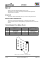
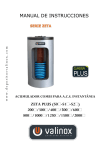
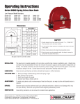
User Manual for
D9300 Series
Digital-Control Color Monitor
© 2001
Aristocrat Technologies, Inc.
All Rights Reserved
D9300
SET UP
Setting up the Wells -Gardner D9300 monitor is easy.
All you have to do is make a few simple connections and adjustments.
The procedure is as follows:
START UP
The monitor starts automatically when you connect to the power source.
SINGLE CABLE CONNECTION
The monitor connects automatically as it is inserted into the cabinet.
Use the standard extension cable (569106) to operate the monitor outside the
cabinet.
12-PIN DRAWER PLUG (BEAU PLUG)
PIN NO.
1
2
3
4
5
6
DESCRIP TION
RED V IDEO
GREEN Video
BLUE Video
Video Ground
V-SYNC
H-SYNC
PIN NO.
7
8
9
10
11
12
DESCRIPTION
Touchscreen RX
Touchscreen GND
Touchscreen TX.
Mains (Hot)
Mains (GND)
Mains (Neut)
1
4
2
7
5
3
10
8
6
11
9
12
AMP 211759-1 Pin Locations - Connection View
© 2001
Aristocrat Technologies, Inc.
Page 2 of 4
D9300
SPECIFICATIONS
Picture Tube
• Size: 18V (17 inch diagonal)
• Dot Pitch: 0.25mm
Signal Input
•
•
Video Input: Analog, Positive Signal (0.7V p-p)
Horizontal Sync: TTL Level, Positive or Negative Pulse
• Scanning: 28 KHz-70KHz
• Vertical Input: TTL Level, Positive or Negative pulse
• Scanning: 40-160Hz
Power Supply
•
•
•
Power Input: 120-240 VAC, 50/60Hz
Fuse Rating: 250V, 3.15A
Power Consumption
Normal: less than 130W
On Screen Display (OSD) Control:
OPERATING T EMPERATURE : 0°C - 55°C
OPERATING H UMIDITY: 10% - 90% (Non-condensing)
NET WEIGHT : 17kg (37lbs) Standard frame
TECHNICAL FEATURES:
Microprocessor control with OSD (On Screen Display) menu
Microprocessor recognizes the input computer signal and the signal output from the
customer control board, connected to the main board by a ribbon cable.
Universal AC Input Voltage
Power supply operates on 120-240 VAC at 60/50Hz for use all over the world.
Protection Circuit for over-current
When an over-current condition occurs in the circuit, the protection circuit operates in
order to prevent the components from electrical shock or other risks.
Override function
A NO SIGNAL message is displayed on the screen if no signal is present at the signal
input cable while the monitor is powered on.
Control panel
If you require different display characteristics other than the factory mode presets of size,
position, color settings, use the control panel to program it to your requirements in each
resolution mode. These adjusted settings remain in memory even if you change resolution
mode or turn off the monitor.
I²C BUS CONTROL
The monitor is designed with I²C BUS control for simplifying the circuitry.
The number of total components is less than 610 pieces.
© 2001
Aristocrat Technologies, Inc.
Page 3 of 4
D9300
SAFETY PRECAUTIONS :
WARNING: Persons not familiar with the necessary safety precautions
on this unit should never attempt to service it.
The following safety precautions are necessary during servicing.
1. Some parts, such as a picture tube in this unit, have special safety-related
characteristics for X-RAY RADIATION protection. For continued safety, parts
replacement should be undertaken referring to article (1-2 and 1-5).
2. Many electrical mechanical parts in this unit have special safety-related
characteristics for protection against shock hazard and others. These characteristics
are often unnoticed by visual inspection and the protection afforded by them cannot
necessarily be obtained by using replacement components rated for higher voltage,
wattage, etc. Replacement parts, which have these special characteristics, are
identified in the service manual and supplements by shading on the schematic
diagram and in the parts list. Before replacing any of these components, read the
parts list in the service manual very carefully.
3. When replacing the chassis in the cabinet, always be certain that all the protective
devices are properly installed, such as insulating covers, strain relief, etc.
4. Thoroughly inspect the inside of the cabinet to see that no stray parts or tools have
been left inside.
5. Before returning the monitor to EX stock, always perform an AC leakage current
check on the exposed metallic parts, such as terminal screw heads, metal overlays,
control shafts, etc.
a. To insure the set is safe to operate without danger of electrical shock, plug
the AC line cord directly into a 120V AC outlet (do not use a line isolation
transformer during this check).
i. Use an AC voltmeter having 5000 ohms per volt or more sensitivity
in the following manner.
ii. Connect a 1500O, 10w resistor, parallel with a 0.15µF capacitor.
b. Voltage measured must not exceed 0.3V RMS.
This corresponds to 0.2mA AC.
i. Any value exceeding this limit constitutes a potential shock hazard
and must be corrected immediately.
c. Reverse the AC plug in the AC outlet and repeat the AC voltage
measurements for each exposed metallic part.
© 2001
Aristocrat Technologies, Inc.
Page 4 of 4