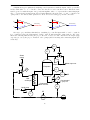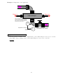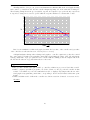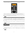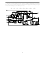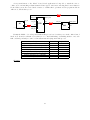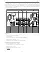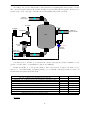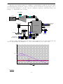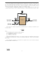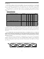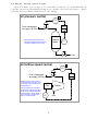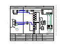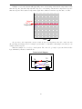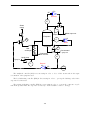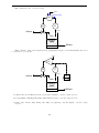
1
INST 262 (DCS and Fieldbus), section 1
Lab
Automatically-controlled process: Questions 91 and 92, completed objectives due by the end of day
5, section 2
Exam
Day 5 of next section
Specific objectives for the “mastery” exam:
• Electricity Review: Calculate voltages, currents, powers and/or resistances in a DC series-parallel circuit
• Identify proper controller action (direct or reverse) for a given process
• Predict the response of a single-loop control system to a component fault or process change
• Identify specific instrument calibration errors (zero, span, linearity, hysteresis) from data in an “AsFound” table
• Solve for a specified variable in an algebraic formula
• Determine the possibility of suggested faults in a 4-20 mA loop circuit given measured values (voltage,
current), a schematic diagram, and reported symptoms
• INST231 Review: Sketch proper wire connections for sourcing or sinking PLC I/O points
• INST240 Review: Determine suitability of different level-measuring technologies for a given process fluid
type
• INST251 Review: Identify the graphed response of a controller as being either P, I, or D
Recommended daily schedule
Day 1
Theory session topic: Feedback control
Questions 1 through 20; answer questions 1-8 in preparation for discussion (remainder for practice)
Day 2
Theory session topic: PID control
Questions 21 through 40; answer questions 21-28 in preparation for discussion (remainder for practice)
Day 3
Theory session topic: Loop controller function block programming
Questions 41 through 60; answer questions 41-45 in preparation for discussion (remainder for practice)
Day 4
Theory session topic: DCS configuration
Questions 61 through 80; answer questions 61-68 in preparation for discussion (remainder for practice)
Feedback questions (81 through 90) are optional and may be submitted for review at the end of the day
1
How To . . .
Access the worksheets and textbook: go to the Socratic Instrumentation website located at
http://www.ibiblio.org/kuphaldt/socratic/sinst to find worksheets for every 2nd-year course section
organized by quarter, as well as both the latest “stable” and “development” versions of the Lessons In
Industrial Instrumentation textbook. Download and save these documents to your computer.
Maximize your learning: come to school prepared each and every day – this means completing all your
homework before class starts. Use every minute of class and lab time productively. Follow all the tips
outlined in “Question 0” (in every course worksheet) as well as your instructor’s advice. Don’t ask anyone
to help you solve a problem until you have made every reasonable effort to solve it on your own.
Identify upcoming assignments and deadlines: read the first page of each course worksheet.
Relate course days to calendar dates: reference the calendar spreadsheet file (calendar.xlsx), found
on the BTC campus Y: network drive. A printed copy is posted in the Instrumentation classroom.
Locate industry documents assigned for reading: use the Instrumentation Reference provided by
your instructor (on CD-ROM and on the BTC campus Y: network drive). There you will find a file named
00 index OPEN THIS FILE.html readable with any internet browser. Click on the “Quick-Start Links” to
access assigned reading documents, organized per course, in the order they are assigned.
Study for the exams: Mastery exams assess specific skills critically important to your success, listed near
the top of the front page of each course worksheet for your review. Familiarize yourself with this list and pay
close attention when those topics appear in homework and practice problems. Proportional exams feature
problems you haven’t seen before that are solvable using general principles learned throughout the current and
previous courses, for which the only adequate preparation is independent problem-solving practice every day.
Answer the “feedback questions” (practice exams) in each course section to hone your problem-solving skills,
as these are similar in scope and complexity to proportional exams. Answer these feedback independently
(i.e. no help from classmates) in order to most accurately assess your readiness.
Calculate course grades: download the “Course Grading Spreadsheet” (grades template.xlsx) from
the Socratic Instrumentation website, or from the BTC campus Y: network drive. Enter your quiz scores,
test scores, lab scores, and attendance data into this Excel spreadsheet and it will calculate your course
grade. You may compare your calculated grades against your instructors’ records at any time.
Identify courses to register for: read the “Sequence” page found in each worksheet.
Identify scholarship opportunities: check your BTC email in-box daily.
Identify job openings: regularly monitor job-search websites. Set up informational interviews at
workplaces you are interested in. Participate in jobshadows and internships. Apply to jobs long before
graduation, as some employers take months to respond! Check your BTC email account daily, because your
instructor broadcast-emails job postings to all students as employers submit them to BTC.
Impress employers: sign the FERPA release form granting your instructors permission to share academic
records, then make sure your performance is worth sharing. Document your project and problem-solving
experiences for reference during interviews. Honor all your commitments.
Begin your career: participate in jobshadows and internships while in school to gain experience and
references. Take the first Instrumentation job that pays the bills, and give that employer at least two years
of good work to pay them back for the investment they have made in you. Employers look at delayed
employment, as well as short employment spans, very negatively. Failure to pass a drug test is an immediate
disqualifier, as is falsifying any information. Criminal records may also be a problem.
file howto
2
General Values and Expectations
Success in this career requires: professional integrity, resourcefulness, persistence, close attention to
detail, and intellectual curiosity. Poor judgment spells disaster in this career, which is why employer
background checks (including social media and criminal records) and drug testing are common. The good
news is that character and clear thinking are malleable traits: unlike intelligence, these qualities can be
acquired and improved with effort. This is what you are in school to do – increase your “human capital”
which is the sum of all knowledge, skills, and traits valuable in the marketplace.
Mastery: You must master the fundamentals of your chosen profession. “Mastery” assessments challenge
you to demonstrate 100% competence (with multiple opportunities to re-try). Failure to complete any
mastery objective(s) by the deadline date caps your grade at a C−. Failure to complete by the end of the
next school day results in a failing (F) grade.
Punctuality and Attendance: You are expected to arrive on time and be “on-task” all day just as you
would for a job. Each student has 12 hours of “sick time” per quarter applicable to absences not verifiably
employment-related, school-related, weather-related, or required by law. Each student must confer with the
instructor to apply these hours to any missed time – this is not done automatically. Students may donate
unused “sick time” to whomever they specifically choose. You must contact your instructor and lab team
members immediately if you know you will be late or absent or must leave early. Absence on an exam day
will result in a zero score for that exam, unless due to a documented emergency.
Time Management: You are expected to budget and prioritize your time, just as you will be on the job.
You will need to reserve enough time outside of school to complete homework, and strategically apply your
time during school hours toward limited resources (e.g. lab equipment). Frivolous activities (e.g. games,
social networking, internet surfing) are unacceptable when work is unfinished. Trips to the cafeteria for food
or coffee, smoke breaks, etc. must not interfere with team participation.
Independent Study: This career is marked by continuous technological development and ongoing change,
which is why self-directed learning is ultimately more important to your future success than specific
knowledge. To acquire and hone this skill, all second-year Instrumentation courses follow an “inverted”
model where lecture is replaced by independent study, and class time is devoted to addressing your questions
and demonstrating your learning. Most students require a minimum of 3 hours daily study time outside of
school. Arriving unprepared (e.g. homework incomplete) is unprofessional and counter-productive. Question
0 of every worksheet lists practical study tips.
Independent Problem-Solving: The best instrument technicians are versatile problem-solvers. General
problem-solving is arguably the most valuable skill you can possess for this career, and it can only be built
through persistent effort. This is why you must take every reasonable measure to solve problems on your own
before seeking help. It is okay to be perplexed by an assignment, but you are expected to apply problemsolving strategies given to you (see Question 0) and to precisely identify where you are confused so your
instructor will be able to offer targeted help. Asking classmates to solve problems for you is folly – this
includes having others break the problem down into simple steps. The point is to learn how to think on your
own. When troubleshooting systems in lab you are expected to run diagnostic tests (e.g. using a multimeter
instead of visually seeking circuit faults), as well as consult the equipment manual(s) before seeking help.
Initiative: No single habit predicts your success or failure in this career better than personal initiative, which
is why your instructor will demand you do for yourself rather than rely on others to do for you. Examples
include setting up and using your BTC email account to communicate with your instructor(s), consulting
manuals for technical information before asking for help, regularly checking the course calendar and
assignment deadlines, avoiding procrastination, fixing small problems before they become larger problems,
etc. If you find your performance compromised by poor understanding of prior course subjects, re-read those
textbook sections and use the practice materials made available to you on the Socratic Instrumentation
website – don’t wait for anyone else to diagnose your need and offer help.
3
General Values and Expectations (continued)
Safety: You are expected to work safely in the lab just as you will be on the job. This includes wearing
proper attire (safety glasses and closed-toed shoes in the lab at all times), implementing lock-out/tag-out
procedures when working on circuits with exposed conductors over 30 volts, using ladders to access elevated
locations, and correctly using all tools. If you need to use an unfamiliar tool, see the instructor for directions.
Orderliness: You are expected to keep your work area clean and orderly just as you will be on the job.
This includes discarding trash and returning tools at the end of every lab session, and participating in all
scheduled lab clean-up sessions. If you identify failed equipment in the lab, label that equipment with a
detailed description of its symptoms.
Teamwork: You will work in instructor-assigned teams to complete lab assignments, just as you will work
in teams to complete complex assignments on the job. As part of a team, you must keep your teammates
informed of your whereabouts in the event you must step away from the lab or will be absent for any reason.
Any student regularly compromising team performance through lack of participation, absence, tardiness,
disrespect, or other disruptive behavior(s) will be removed from the team and required to complete all
labwork individually for the remainder of the quarter. The same is true for students found relying on
teammates to do their work for them.
Cooperation: The structure of these courses naturally lends itself to cooperation between students. Working
together, students significantly impact each others’ learning. You are expected to take this role seriously,
offering real help when needed and not absolving classmates of their responsibility to think for themselves or
to do their own work. Solving problems for classmates and/or explaining to them what they can easily read
on their own is unacceptable because these actions circumvent learning. The best form of help you can give
to your struggling classmates is to share with them your tips on independent learning and problem-solving,
for example asking questions leading to solutions rather than simply providing solutions for them.
Grades: Employers prize trustworthy, hard working, knowledgeable, resourceful problem-solvers. The grade
you receive in any course is but a partial measure of these traits. What matters most are the traits
themselves, which is why your instructor maintains detailed student records (including individual exam
scores, attendance, tardiness, and behavioral comments) and will share these records with employers if
you have signed the FERPA release form. You are welcome to see your records at any time, and to
compare calculated grades with your own records (i.e. the grade spreadsheet available to all students).
You should expect employers to scrutinize your records on attendance and character, and also challenge you
with technical questions when considering you for employment.
Representation: You are an ambassador for this program. Your actions, whether on tours, during a
jobshadow or internship, or while employed, can open or shut doors of opportunity for other students. Most
of the job opportunities open to you as a BTC graduate were earned by the good work of previous graduates,
and as such you owe them a debt of gratitude. Future graduates depend on you to do the same.
Responsibility For Actions: If you lose or damage college property (e.g. lab equipment), you must find,
repair, or help replace it. If you represent BTC poorly to employers (e.g. during a tour or an internship),
you must make amends. The general rule here is this: “If you break it, you fix it!”
Non-negotiable terms: disciplinary action, up to and including immediate failure of a course, will
result from academic dishonesty (e.g. cheating, plagiarism), willful safety violations, theft, harassment,
intoxication, destruction of property, or willful disruption of the learning (work) environment. Such offenses
are grounds for immediate termination in this career, and as such will not be tolerated here.
file expectations
4
Course Syllabus
INSTRUCTOR CONTACT INFORMATION:
Tony Kuphaldt
(360)-752-8477 [office phone]
(360)-752-7277 [fax]
[email protected]
DEPT/COURSE #: INST 262
CREDITS: 5
Lecture Hours: 22
Lab Hours: 70
Work-based Hours: 0
COURSE TITLE: Digital Control Systems
COURSE DESCRIPTION: This course teaches the basic principles of distributed instrumentation,
including distributed control systems (DCS), FOUNDATION Fieldbus instruments, and wireless field
instruments. Pre/Corequisite course: INST 260 (Data Acquisition Systems) Prerequisite course:
MATH&141 (Precalculus 1) with a minimum grade of “C”
COURSE OUTCOMES: Commission, analyze, and efficiently diagnose instrumented systems
incorporating networked control platforms (DCS, Fieldbus, wireless).
COURSE OUTCOME ASSESSMENT: DCS and Fieldbus system commissioning, analysis, and
diagnosis outcomes are ensured by measuring student performance against mastery standards, as documented
in the Student Performance Objectives. Failure to meet all mastery standards by the next scheduled exam
day will result in a failing grade for the course.
5
STUDENT PERFORMANCE OBJECTIVES:
• Without references or notes, within a limited time (3 hours total for each exam session), independently
perform the following tasks. Multiple re-tries are allowed on mastery (100% accuracy) objectives, each
with a different set of problems:
→ Calculate voltages, currents, powers, and/or resistances in a DC series-parallel circuit, with 100%
accuracy (mastery)
→ Calculate voltages and currents in an ideal AC transformer circuit, with 100% accuracy (mastery)
→ Identify proper controller action for a given process with 100% accuracy (mastery)
→ Predict the response of a single-loop control system to a component fault or process change, given
pictorial and/or schematic illustrations, with 100% accuracy (mastery)
→ Determine proper AI block parameters to range a Fieldbus transmitter for a given application, with
100% accuracy (mastery)
→ Use decibels to calculate power gains and losses with 100% accuracy (mastery)
→ Calculate instrument input and output values given calibrated ranges, with 100% accuracy (mastery)
→ Identify specific instrument calibration errors (zero, span, linearity, hysteresis) from data in an “AsFound” table, with 100% accuracy (mastery)
→ Solve for specified variables in algebraic formulae, with 100% accuracy (mastery)
→ Determine the possibility of suggested faults in a simple circuit given measured values (voltage,
current), a schematic diagram, and reported symptoms, with 100% accuracy (mastery)
→ Sketch proper power and signal connections between individual instruments to fulfill specified control
system functions, given pictorial and/or schematic illustrations of those instruments
• In a team environment and with full access to references, notes, and instructor assistance, perform the
following tasks:
→ Demonstrate proper use of safety equipment and application of safe procedures while using power
tools, and working on live systems
→ Communicate effectively with teammates to plan work, arrange for absences, and share responsibilities
in completing all labwork
→ Construct and commission an automatically-controlled process using a PID controller
→ Generate an accurate loop diagram compliant with ISA standards documenting your team’s control
system
→ Commission and decommission a WirelessHART instrument
→ Configure a digital indicator to poll instrument data via the Modbus protocol
• Independently perform the following tasks with 100% accuracy (mastery). Multiple re-tries are allowed
with different specifications/conditions each time:
→ Connect an electromechanical interposing relay to energize a 120 VAC load using a DC control circuit,
given components and criteria randomly selected by the instructor
→ Build a circuit and configure a HART-compatible DP transmitter to measure an applied pressure or
vacuum according to criteria randomly selected by the instructor
→ Diagnose a random fault placed in another team’s control system by the instructor within a limited
time using no test equipment except a multimeter, logically justifying your steps in the instructor’s
direct presence
COURSE OUTLINE: A course calendar in electronic format (Excel spreadsheet) resides on the Y:
network drive, and also in printed paper format in classroom DMC130, for convenient student access. This
calendar is updated to reflect schedule changes resulting from employer recruiting visits, interviews, and
other impromptu events. Course worksheets provide comprehensive lists of all course assignments and
activities, with the first page outlining the schedule and sequencing of topics and assignment due dates.
These worksheets are available in PDF format at http://www.ibiblio.org/kuphaldt/socratic/sinst
• INST262 Section 1 (Feedback control systems): 4 days theory and labwork
• INST262 Section 2 (DDC and DCS platforms): 4 days theory and labwork + 1 day for
mastery/proportional Exams
• INST262 Section 3 (FOUNDATION Fieldbus): 4 days theory and labwork
6
• INST262 Section 4 (Wireless instrumentation):
mastery/proportional Exams
4 days theory and labwork + 1 day for
METHODS OF INSTRUCTION: Course structure and methods are intentionally designed to develop
critical-thinking and life-long learning abilities, continually placing the student in an active rather than a
passive role.
• Independent study: daily worksheet questions specify reading assignments, problems to solve, and
experiments to perform in preparation (before) classroom theory sessions. Open-note quizzes and work
inspections ensure accountability for this essential preparatory work. The purpose of this is to convey
information and basic concepts, so valuable class time isn’t wasted transmitting bare facts, and also to
foster the independent research ability necessary for self-directed learning in your career.
• Classroom sessions: a combination of Socratic discussion, short lectures, small-group problem-solving,
and hands-on demonstrations/experiments review and illuminate concepts covered in the preparatory
questions. The purpose of this is to develop problem-solving skills, strengthen conceptual understanding,
and practice both quantitative and qualitative analysis techniques.
• Lab activities: an emphasis on constructing and documenting working projects (real instrumentation
and control systems) to illuminate theoretical knowledge with practical contexts. Special projects
off-campus or in different areas of campus (e.g. BTC’s Fish Hatchery) are encouraged. Hands-on
troubleshooting exercises build diagnostic skills.
• Feedback questions: sets of practice problems at the end of each course section challenge your
knowledge and problem-solving ability in current as as well as first year (Electronics) subjects. These
are optional assignments, counting neither for nor against your grade. Their purpose is to provide you
and your instructor with direct feedback on what you have learned.
• Tours and guest speakers: quarterly tours of local industry and guest speakers on technical topics
add breadth and additional context to the learning experience.
STUDENT ASSIGNMENTS/REQUIREMENTS: All assignments for this course are thoroughly
documented in the following course worksheets located at:
http://www.ibiblio.org/kuphaldt/socratic/sinst/index.html
•
•
•
•
INST262
INST262
INST262
INST262
sec1.pdf
sec2.pdf
sec3.pdf
sec4.pdf
7
EVALUATION AND GRADING STANDARDS: (out of 100% for the course grade)
• Completion of all mastery objectives = 50%
• Mastery exam scores (first attempt) = 10% (2 exams at 5% each)
• Proportional exam scores = 30% (2 exams at 15% each)
• Lab questions = 10% (2 question sets at 5% each)
• Quiz penalty = -1% per failed quiz
• Tardiness penalty = -1% per incident (1 “free” tardy per course)
• Attendance penalty = -1% per hour (12 hours “sick time” per quarter)
• Extra credit = +5% per project (assigned by instructor based on individual learning needs)
All grades are criterion-referenced (i.e. no grading on a “curve”)
100% ≥ A ≥ 95%
90% > B+ ≥ 86%
80% > C+ ≥ 76%
70% > D+ ≥ 66%
95% > A- ≥ 90%
86% > B ≥ 83%
76% > C ≥ 73%
66% > D ≥ 63%
83% > B- ≥ 80%
73% > C- ≥ 70% (minimum passing course grade)
63% > D- ≥ 60%
60% > F
A graded “preparatory” quiz at the start of each classroom session gauges your independent learning
prior to the session. A graded “summary” quiz at the conclusion of each classroom session gauges your
comprehension of important concepts covered during that session. If absent during part or all of a classroom
session, you may receive credit by passing comparable quizzes afterward or by having your preparatory work
(reading outlines, work done answering questions) thoroughly reviewed prior to the absence.
Absence on a scheduled exam day will result in a 0% score for the proportional exam unless you provide
documented evidence of an unavoidable emergency.
If you fail a mastery exam, you must re-take a different version of that mastery exam on a different
day. Multiple re-tries are allowed, on a different version of the exam each re-try. There is no penalty levied
on your course grade for re-taking mastery exams, but failure to successfully pass a mastery exam by the
due date (i.e. by the date of the next exam in the course sequence) will result in a failing grade (F) for the
course.
If any other “mastery” objectives are not completed by their specified deadlines, your overall grade
for the course will be capped at 70% (C- grade), and you will have one more school day to complete the
unfinished objectives. Failure to complete those mastery objectives by the end of that extra day (except in
the case of documented, unavoidable emergencies) will result in a failing grade (F) for the course.
“Lab questions” are assessed by individual questioning, at any date after the respective lab objective
(mastery) has been completed by your team. These questions serve to guide your completion of each lab
exercise and confirm participation of each individual student. Grading is as follows: full credit for thorough,
correct answers; half credit for partially correct answers; and zero credit for major conceptual errors. All
lab questions must be answered by the due date of the lab exercise.
Extra credit opportunities exist for each course, and may be assigned to students upon request. The
student and the instructor will first review the student’s performance on feedback questions, homework,
exams, and any other relevant indicators in order to identify areas of conceptual or practical weakness. Then,
both will work together to select an appropriate extra credit activity focusing on those identified weaknesses,
for the purpose of strengthening the student’s competence. A due date will be assigned (typically two weeks
following the request), which must be honored in order for any credit to be earned from the activity. Extra
credit may be denied at the instructor’s discretion if the student has not invested the necessary preparatory
effort to perform well (e.g. lack of preparation for daily class sessions, poor attendance, no feedback questions
submitted, etc.).
8
REQUIRED STUDENT SUPPLIES AND MATERIALS:
• Course worksheets available for download in PDF format
• Lessons in Industrial Instrumentation textbook, available for download in PDF format
→ Access worksheets and book at: http://www.ibiblio.org/kuphaldt/socratic/sinst
• Spiral-bound notebook for reading annotation, homework documentation, and note-taking.
• Instrumentation reference CD-ROM (free, from instructor). This disk contains many tutorials and
datasheets in PDF format to supplement your textbook(s).
• Tool kit (see detailed list)
• Simple scientific calculator (non-programmable, non-graphing, no unit conversions, no numeration
system conversions), TI-30Xa or TI-30XIIS recommended
ADDITIONAL INSTRUCTIONAL RESOURCES:
• The BTC Library hosts a substantial collection of textbooks and references on the subject of
Instrumentation, as well as links in its online catalog to free Instrumentation e-book resources available
on the Internet.
• “BTCInstrumentation” channel on YouTube (http://www.youtube.com/BTCInstrumentation), hosts
a variety of short video tutorials and demonstrations on instrumentation.
• ISA Student Section at BTC meets regularly to set up industry tours, raise funds for scholarships,
and serve as a general resource for Instrumentation students. Membership in the ISA is $10 per year,
payable to the national ISA organization. Membership includes a complementary subscription to InTech
magazine.
• ISA website (http://www.isa.org) provides all of its standards in electronic format, many of which
are freely available to ISA members.
• Normal Accidents, by Charles Perrow. ISBN-10: 0691004129 ; ISBN-13: 978-0691004129.
• Instrument Engineer’s Handbook, Volume 2: Process Control and Optimization, edited by Béla Lipták,
published by CRC Press. 4th edition ISBN-10: 0849310814 ; ISBN-13: 978-0849310812.
• Purdy’s Instrument Handbook, by Ralph Dewey. ISBN-10: 1-880215-26-8. A pocket-sized field reference
on basic measurement and control.
• Cad Standard (CadStd) or similar AutoCAD-like drafting software (useful for sketching loop and
wiring diagrams). Cad Standard is a simplified clone of AutoCAD, and is freely available at:
http://www.cadstd.com
CAMPUS EMERGENCIES: If an emergency arises, your instructor may inform you of actions to
follow. You are responsible for knowing emergency evacuation routes from your classroom. If police or
university officials order you to evacuate, do so calmly and assist those needing help. You may receive
emergency information alerts via the building enunciation system, text message, email, or BTC’s webpage
(http://www.btc.ctc.edu), Facebook or Twitter. Refer to the emergency flipchart in the lab room (located
on the main control panel) for more information on specific types of emergencies.
ACCOMMODATIONS: If you think you could benefit from classroom accommodations for a disability
(physical, mental, emotional, or learning), please contact our Accessibility Resources office. Call (360)-7528345, email [email protected], or stop by the AR Office in the Admissions and Student Resource Center
(ASRC), Room 106, College Services Building
file INST262syllabus
9
Sequence of second-year Instrumentation courses
Core Electronics -- 3 qtrs
including MATH 141 (Precalculus 1)
(Only if 4th quarter was Summer: INST23x)
INST 200 -- 1 wk
Intro. to Instrumentation
Prerequisite for all INST24x,
INST25x, and INST26x courses
Summer quarter
Fall quarter
Winter quarter
Offered 1st week of
Fall, Winter, and
Spring quarters
Spring quarter
INST 230 -- 3 cr
INST 240 -- 6 cr
INST 250 -- 5 cr
INST 260 -- 4 cr
Motor Controls
Pressure/Level Measurement
Final Control Elements
Data Acquisition Systems
INST 231 -- 3 cr
INST 241 -- 6 cr
INST 251 -- 5 cr
INST 262 -- 5 cr
PLC Programming
Temp./Flow Measurement
PID Control
DCS and Fieldbus
INST 232 -- 3 cr
INST 242 -- 5 cr
INST 252 -- 4 cr
INST 263 -- 5 cr
Loop Tuning
Control Strategies
PLC Systems
Analytical Measurement
INST 233 -- 3 cr
CHEM&161 -- 5 cr
Protective Relays (elective)
Chemistry
ENGT 134 -- 5 cr
CAD 1: Basics
Prerequisite for INST206
All courses
completed?
Yes
INST 205 -- 1 cr
Job Prep I
No
INST 206 -- 1 cr
Job Prep II
Graduate!!!
10
Offered 1st week of
Fall, Winter, and
Spring quarters
The particular sequence of courses you take during the second year depends on when you complete all
first-year courses and enter the second year. Since students enter the second year of Instrumentation at four
different times (beginnings of Summer, Fall, Winter, and Spring quarters), the particular course sequence
for any student will likely be different from the course sequence of classmates.
Some second-year courses are only offered in particular quarters with those quarters not having to be
in sequence, while others are offered three out of the four quarters and must be taken in sequence. The
following layout shows four typical course sequences for second-year Instrumentation students, depending on
when they first enter the second year of the program:
Possible course schedules depending on date of entry into 2nd year
Beginning in Summer
July
Summer quarter
Beginning in Fall
Sept.
Intro. to Instrumentation
Intro. to Instrumentation
Intro. to Instrumentation
INST 231 -- 3 cr
INST 240 -- 6 cr
INST 250 -- 5 cr
INST 260 -- 4 cr
PLC Programming
Pressure/Level Measurement
Final Control Elements
Data Acquisition Systems
Protective Relays (elective)
Fall quarter
Dec.
Jan.
INST 251 -- 5 cr
INST 262 -- 5 cr
PID Control
DCS and Fieldbus
INST 242 -- 5 cr
INST 252 -- 4 cr
INST 263 -- 5 cr
Loop Tuning
Control Strategies
Analytical Measurement
CHEM&161 -- 5 cr
Winter quarter
Intro. to Instrumentation
INST 240 -- 6 cr
INST 250 -- 5 cr
Pressure/Level Measurement
INST 241 -- 6 cr
Mar.
April
Chemistry
Spring quarter
ENGT 134 -- 5 cr
June
July
CAD 1: Basics
Summer quarter
INST 230 -- 3 cr
Final Control Elements
INST 205 -- 1 cr
Job Prep I
INST 251 -- 5 cr
INST 260 -- 4 cr
INST 231 -- 3 cr
Temp./Flow Measurement
PID Control
Data Acquisition Systems
PLC Programming
INST 242 -- 5 cr
INST 252 -- 4 cr
INST 262 -- 5 cr
INST 232 -- 3 cr
Loop Tuning
DCS and Fieldbus
CHEM&161 -- 5 cr
INST 263 -- 5 cr
Chemistry
Control Strategies
Analytical Measurement
Winter quarter
Mar.
April
ENGT 134 -- 5 cr
Spring quarter
June
CAD 1: Basics
Motor Controls
PLC Systems
INST 233 -- 3 cr
Aug.
Sept.
Protective Relays (elective)
Fall quarter
Final Control Elements
INST 206 -- 1 cr
Job Prep II
INST 251 -- 5 cr
INST 260 -- 4 cr
INST 230 -- 3 cr
INST 240 -- 6 cr
PID Control
Data Acquisition Systems
Motor Controls
Pressure/Level Measurement
INST 252 -- 4 cr
INST 262 -- 5 cr
INST 231 -- 3 cr
INST 241 -- 6 cr
Loop Tuning
DCS and Fieldbus
PLC Programming
Temp./Flow Measurement
CHEM&161 -- 5 cr
INST 263 -- 5 cr
INST 232 -- 3 cr
Chemistry
Control Strategies
Spring quarter
INST 206 -- 1 cr
Job Prep II
July
Summer quarter
INST 230 -- 3 cr
Data Acquisition Systems
Motor Controls
INST 262 -- 5 cr
DCS and Fieldbus
INST 263 -- 5 cr
INST 232 -- 3 cr
Sept.
Jan.
Analytical Measurement
Winter quarter
INST 206 -- 1 cr
Job Prep II
Fall quarter
INST 250 -- 5 cr
INST 231 -- 3 cr
INST 240 -- 6 cr
INST 251 -- 5 cr
PLC Programming
Pressure/Level Measurement
PID Control
INST 241 -- 6 cr
INST 252 -- 4 cr
Temp./Flow Measurement
Loop Tuning
INST 233 -- 3 cr
Aug.
Protective Relays (elective)
INST 242 -- 5 cr
Dec.
INST 206 -- 1 cr
Job Prep II
PLC Systems
ENGT 134 -- 5 cr
Graduation!
INST 233 -- 3 cr
Aug.
INST 205 -- 1 cr
Job Prep I
Summer quarter
PLC Systems
CAD 1: Basics
INST 260 -- 4 cr
CAD 1: Basics
July
ENGT 134 -- 5 cr
June
Control Strategies
June
INST 241 -- 6 cr
Temp./Flow Measurement
INST 205 -- 1 cr
Job Prep I
INST 250 -- 5 cr
April
Spring quarter
Motor Controls
INST 205 -- 1 cr
Job Prep I
Mar.
April
INST 200 -- 1 wk
INST 200 -- 1 wk
Jan.
Winter quarter
INST 200 -- 1 wk
INST 233 -- 3 cr
Dec.
Jan.
INST 200 -- 1 wk
PLC Systems
Sept.
Fall quarter
Beginning in Spring
INST 230 -- 3 cr
INST 232 -- 3 cr
Aug.
Beginning in Winter
Final Control Elements
INST 242 -- 5 cr
Protective Relays (elective)
Dec.
Graduation!
Analytical Measurement
Graduation!
file sequence
11
CHEM&161 -- 5 cr
Mar.
Chemistry
Graduation!
General tool and supply list
Wrenches
• Combination (box- and open-end) wrench set, 1/4” to 3/4” – the most important wrench sizes are 7/16”,
1/2”, 9/16”, and 5/8”; get these immediately!
• Adjustable wrench, 6” handle (sometimes called “Crescent” wrench)
• Hex wrench (“Allen” wrench) set, fractional – 1/16” to 3/8”
• Optional: Hex wrench (“Allen” wrench) set, metric – 1.5 mm to 10 mm
• Optional: Miniature combination wrench set, 3/32” to 1/4” (sometimes called an “ignition wrench” set)
Note: when turning any threaded fastener, one should choose a tool engaging the maximum amount of
surface area on the fastener’s head in order to reduce stress on that fastener. (e.g. Using box-end wrenches
instead of adjustable wrenches; using the proper size and type of screwdriver; never using any tool that mars
the fastener such as pliers or vise-grips unless absolutely necessary.)
Pliers
• Needle-nose pliers
• Tongue-and-groove pliers (sometimes called “Channel-lock” pliers)
• Diagonal wire cutters (sometimes called “dikes”)
Screwdrivers
• Slotted, 1/8” and 1/4” shaft
• Phillips, #1 and #2
• Jeweler’s screwdriver set
• Optional: Magnetic multi-bit screwdriver (e.g. Klein Tools model 70035)
Electrical
• Multimeter, Fluke model 87-IV or better
• Alligator-clip jumper wires
• Soldering iron (10 to 40 watt) and rosin-core solder
• Resistor, potentiometer, diode assortments (from first-year lab kits)
• Package of insulated compression-style fork terminals (14 to 18 AWG wire size, #10 stud size)
• Wire strippers/terminal crimpers for 10 AWG to 18 AWG wire and insulated terminals
• Optional: ratcheting terminal crimp tool (e.g. Paladin 1305, Ferrules Direct FDT10011, or equivalent)
Safety
• Safety glasses or goggles (available at BTC bookstore)
• Earplugs (available at BTC bookstore)
Miscellaneous
• Simple scientific calculator (non-programmable, non-graphing, no conversions), TI-30Xa or TI-30XIIS
recommended. Required for some exams!
• Masking tape (for making temporary labels)
• Permanent marker pen
• Teflon pipe tape
• Utility knife
• Tape measure, 12 feet minimum
• Flashlight
An inexpensive source of tools is your local pawn shop. Look for tools with unlimited lifetime guarantees
(e.g. Sears “Craftsman” brand). Check for BTC student discounts as well!
file tools
12
Methods of instruction
This course develops self-instructional and diagnostic skills by placing students in situations where they
are required to research and think independently. In all portions of the curriculum, the goal is to avoid a
passive learning environment, favoring instead active engagement of the learner through reading, reflection,
problem-solving, and experimental activities. The curriculum may be roughly divided into two portions:
theory and practical.
Theory
In the theory portion of each course, students independently research subjects prior to entering the
classroom for discussion. This means working through all the day’s assigned questions as completely as
possible. This usually requires a fair amount of technical reading, and may also require setting up and
running simple experiments. At the start of the classroom session, the instructor will check each student’s
preparation with a quiz. Students then spend the rest of the classroom time working in groups and directly
with the instructor to thoroughly answer all questions assigned for that day, articulate problem-solving
strategies, and to approach the questions from multiple perspectives. To put it simply: fact-gathering
happens outside of class and is the individual responsibility of each student, so that class time may be
devoted to the more complex tasks of critical thinking and problem solving where the instructor’s attention
is best applied.
Classroom theory sessions usually begin with either a brief Q&A discussion or with a “Virtual
Troubleshooting” session where the instructor shows one of the day’s diagnostic question diagrams while
students propose diagnostic tests and the instructor tells those students what the test results would be
given some imagined (“virtual”) fault scenario, writing the test results on the board where all can see. The
students then attempt to identify the nature and location of the fault, based on the test results.
Each student is free to leave the classroom when they have completely worked through all problems and
have answered a “summary” quiz designed to gauge their learning during the theory session. If a student
finishes ahead of time, they are free to leave, or may help tutor classmates who need extra help.
The express goal of this “inverted classroom” teaching methodology is to help each student cultivate
critical-thinking and problem-solving skills, and to sharpen their abilities as independent learners. While
this approach may be very new to you, it is more realistic and beneficial to the type of work done in
instrumentation, where critical thinking, problem-solving, and independent learning are “must-have” skills.
13
Lab
In the lab portion of each course, students work in teams to install, configure, document, calibrate, and
troubleshoot working instrument loop systems. Each lab exercise focuses on a different type of instrument,
with a eight-day period typically allotted for completion. An ordinary lab session might look like this:
(1) Start of practical (lab) session: announcements and planning
(a) The instructor makes general announcements to all students
(b) The instructor works with team to plan that day’s goals, making sure each team member has a
clear idea of what they should accomplish
(2) Teams work on lab unit completion according to recommended schedule:
(First day) Select and bench-test instrument(s)
(One day) Connect instrument(s) into a complete loop
(One day) Each team member drafts their own loop documentation, inspection done as a team (with
instructor)
(One or two days) Each team member calibrates/configures the instrument(s)
(Remaining days, up to last) Each team member troubleshoots the instrument loop
(3) End of practical (lab) session: debriefing where each team reports on their work to the whole class
Troubleshooting assessments must meet the following guidelines:
• Troubleshooting must be performed on a system the student did not build themselves. This forces
students to rely on another team’s documentation rather than their own memory of how the system was
built.
• Each student must individually demonstrate proper troubleshooting technique.
• Simply finding the fault is not good enough. Each student must consistently demonstrate sound
reasoning while troubleshooting.
• If a student fails to properly diagnose the system fault, they must attempt (as many times as necessary)
with different scenarios until they do, reviewing any mistakes with the instructor after each failed
attempt.
file instructional
14
Distance delivery methods
Sometimes the demands of life prevent students from attending college 6 hours per day. In such cases,
there exist alternatives to the normal 8:00 AM to 3:00 PM class/lab schedule, allowing students to complete
coursework in non-traditional ways, at a “distance” from the college campus proper.
For such “distance” students, the same worksheets, lab activities, exams, and academic standards still
apply. Instead of working in small groups and in teams to complete theory and lab sections, though, students
participating in an alternative fashion must do all the work themselves. Participation via teleconferencing,
video- or audio-recorded small-group sessions, and such is encouraged and supported.
There is no recording of hours attended or tardiness for students participating in this manner. The pace
of the course is likewise determined by the “distance” student. Experience has shown that it is a benefit for
“distance” students to maintain the same pace as their on-campus classmates whenever possible.
In lieu of small-group activities and class discussions, comprehension of the theory portion of each course
will be ensured by completing and submitting detailed answers for all worksheet questions, not just passing
daily quizzes as is the standard for conventional students. The instructor will discuss any incomplete and/or
incorrect worksheet answers with the student, and ask that those questions be re-answered by the student
to correct any misunderstandings before moving on.
Labwork is perhaps the most difficult portion of the curriculum for a “distance” student to complete,
since the equipment used in Instrumentation is typically too large and expensive to leave the school lab
facility. “Distance” students must find a way to complete the required lab activities, either by arranging
time in the school lab facility and/or completing activities on equivalent equipment outside of school (e.g.
at their place of employment, if applicable). Labwork completed outside of school must be validated by a
supervisor and/or documented via photograph or videorecording.
Conventional students may opt to switch to “distance” mode at any time. This has proven to be a
benefit to students whose lives are disrupted by catastrophic events. Likewise, “distance” students may
switch back to conventional mode if and when their schedules permit. Although the existence of alternative
modes of student participation is a great benefit for students with challenging schedules, it requires a greater
investment of time and a greater level of self-discipline than the traditional mode where the student attends
school for 6 hours every day. No student should consider the “distance” mode of learning a way to have
more free time to themselves, because they will actually spend more time engaged in the coursework than
if they attend school on a regular schedule. It exists merely for the sake of those who cannot attend during
regular school hours, as an alternative to course withdrawal.
file distance
15
Metric prefixes and conversion constants
•
•
•
•
•
•
•
•
•
•
•
•
•
•
•
•
•
•
•
•
•
Metric prefixes
Yotta = 1024 Symbol: Y
Zeta = 1021 Symbol: Z
Exa = 1018 Symbol: E
Peta = 1015 Symbol: P
Tera = 1012 Symbol: T
Giga = 109 Symbol: G
Mega = 106 Symbol: M
Kilo = 103 Symbol: k
Hecto = 102 Symbol: h
Deca = 101 Symbol: da
Deci = 10−1 Symbol: d
Centi = 10−2 Symbol: c
Milli = 10−3 Symbol: m
Micro = 10−6 Symbol: µ
Nano = 10−9 Symbol: n
Pico = 10−12 Symbol: p
Femto = 10−15 Symbol: f
Atto = 10−18 Symbol: a
Zepto = 10−21 Symbol: z
Yocto = 10−24 Symbol: y
METRIC PREFIX SCALE
T
tera
1012
G
M
giga mega
109
106
k
kilo
103
(none)
100
m
µ
milli micro
10-3 10-6
102 101 10-1 10-2
hecto deca deci centi
h
da
d
c
•
•
•
•
•
Conversion formulae for temperature
F = (o C)(9/5) + 32
o
C = (o F - 32)(5/9)
o
R = o F + 459.67
K = o C + 273.15
o
Conversion equivalencies for distance
1 inch (in) = 2.540000 centimeter (cm)
1 foot (ft) = 12 inches (in)
1 yard (yd) = 3 feet (ft)
1 mile (mi) = 5280 feet (ft)
16
n
nano
10-9
p
pico
10-12
Conversion equivalencies for volume
1 gallon (gal) = 231.0 cubic inches (in3 ) = 4 quarts (qt) = 8 pints (pt) = 128 fluid ounces (fl. oz.)
= 3.7854 liters (l)
1 milliliter (ml) = 1 cubic centimeter (cm3 )
Conversion equivalencies for velocity
1 mile per hour (mi/h) = 88 feet per minute (ft/m) = 1.46667 feet per second (ft/s) = 1.60934
kilometer per hour (km/h) = 0.44704 meter per second (m/s) = 0.868976 knot (knot – international)
Conversion equivalencies for mass
1 pound (lbm) = 0.45359 kilogram (kg) = 0.031081 slugs
Conversion equivalencies for force
1 pound-force (lbf) = 4.44822 newton (N)
Conversion equivalencies for area
1 acre = 43560 square feet (ft2 ) = 4840 square yards (yd2 ) = 4046.86 square meters (m2 )
Conversion equivalencies for common pressure units (either all gauge or all absolute)
1 pound per square inch (PSI) = 2.03602 inches of mercury (in. Hg) = 27.6799 inches of water (in.
W.C.) = 6.894757 kilo-pascals (kPa) = 0.06894757 bar
1 bar = 100 kilo-pascals (kPa) = 14.504 pounds per square inch (PSI)
Conversion equivalencies for absolute pressure units (only)
1 atmosphere (Atm) = 14.7 pounds per square inch absolute (PSIA) = 101.325 kilo-pascals absolute
(kPaA) = 1.01325 bar (bar) = 760 millimeters of mercury absolute (mmHgA) = 760 torr (torr)
Conversion equivalencies for energy or work
1 british thermal unit (Btu – “International Table”) = 251.996 calories (cal – “International Table”)
= 1055.06 joules (J) = 1055.06 watt-seconds (W-s) = 0.293071 watt-hour (W-hr) = 1.05506 x 10¹⁰
ergs (erg) = 778.169 foot-pound-force (ft-lbf)
Conversion equivalencies for power
1 horsepower (hp – 550 ft-lbf/s) = 745.7 watts (W) = 2544.43 british thermal units per hour
(Btu/hr) = 0.0760181 boiler horsepower (hp – boiler)
Acceleration of gravity (free fall), Earth standard
9.806650 meters per second per second (m/s2 ) = 32.1740 feet per second per second (ft/s2 )
17
Physical constants
Speed of light in a vacuum (c) = 2.9979 × 10⁸ meters per second (m/s) = 186,281 miles per second
(mi/s)
Avogadro’s number (NA ) = 6.022 × 10²³ per mole (mol−1 )
Electronic charge (e) = 1.602 × 10⁻¹⁹ Coulomb (C)
Boltzmann’s constant (k) = 1.38 × 10⁻²³ Joules per Kelvin (J/K)
Stefan-Boltzmann constant (σ) = 5.67 × 10⁻⁸ Watts per square meter-Kelvin4 (W/m2 ·K4 )
Molar gas constant (R) = 8.314 Joules per mole-Kelvin (J/mol-K)
Properties of Water
Freezing point at sea level = 32o F = 0o C
Boiling point at sea level = 212o F = 100o C
Density of water at 4o C = 1000 kg/m3 = 1 g/cm3 = 1 kg/liter = 62.428 lb/ft3 = 1.94 slugs/ft3
Specific heat of water at 14o C = 1.00002 calories/g·o C = 1 BTU/lb·o F = 4.1869 Joules/g·o C
Specific heat of ice ≈ 0.5 calories/g·o C
Specific heat of steam ≈ 0.48 calories/g·o C
Absolute viscosity of water at 20o C = 1.0019 centipoise (cp) = 0.0010019 Pascal-seconds (Pa·s)
Surface tension of water (in contact with air) at 18o C = 73.05 dynes/cm
pH of pure water at 25o C = 7.0 (pH scale = 0 to 14)
Properties of Dry Air at sea level
Density of dry air at 20o C and 760 torr = 1.204 mg/cm3 = 1.204 kg/m3 = 0.075 lb/ft3 = 0.00235
slugs/ft3
Absolute viscosity of dry air at 20o C and 760 torr = 0.018 centipoise (cp) = 1.8 × 10⁻⁵ Pascalseconds (Pa·s)
file conversion constants
18
Question 0
How to get the most out of academic reading:
• Articulate your thoughts as you read (i.e. “have a conversation” with the author). This will develop
metacognition: active supervision of your own thoughts. Write your thoughts as you read, noting
points of agreement, disagreement, confusion, epiphanies, and connections between different concepts
or applications. These notes should also document important math formulae, explaining in your own
words what each formula means and the proper units of measurement used.
• Outline, don’t highlight! Writing your own summary or outline is a far more effective way to comprehend
a text than simply underlining and highlighting key words. A suggested ratio is one sentence of your
own thoughts per paragraph of text read. Note points of disagreement or confusion to explore later.
• Work through all mathematical exercises shown within the text, to ensure you understand all the steps.
• Imagine explaining concepts you’ve just learned to someone else. Teaching forces you to distill concepts
to their essence, thereby clarifying those concepts, revealing assumptions, and exposing misconceptions.
Your goal is to create the simplest explanation that is still technically accurate.
• Write your own questions based on what you read, as though you are a teacher preparing to test
students’ comprehension of the subject matter.
How to effectively problem-solve and troubleshoot:
• Study principles, not procedures. Don’t be satisfied with merely knowing how to compute solutions –
learn why those solutions work. In mathematical problem-solving this means being able to identify the
practical meaning (and units of measurement) of every intermediate calculation. In other words, every
step of your solution should make logical sense.
• Sketch a diagram to help visualize the problem. When building a real system, always prototype it on
paper and analyze its function before constructing it.
• Identify what it is you need to solve, identify all relevant data, identify all units of measurement, identify
any general principles or formulae linking the given information to the solution, and then identify any
“missing pieces” to a solution. Annotate all diagrams with this data.
• Perform “thought experiments” to explore the effects of different conditions for theoretical problems.
When troubleshooting real systems, perform diagnostic tests rather than visually inspecting for faults.
• Simplify the problem and solve that simplified problem to identify strategies applicable to the original
problem (e.g. change quantitative to qualitative, or visa-versa; substitute easier numerical values;
eliminate confusing details; add details to eliminate unknowns; consider simple limiting cases; apply an
analogy). Often you can add or remove components in a malfunctioning system to simplify it as well
and better identify the nature and location of the problem.
• Work “backward” from a hypothetical solution to a new set of given conditions.
How to create more time for study:
• Kill your television and video games. Seriously – these are incredible wastes of time.
distractions (e.g. cell phone, internet, socializing) in your place and time of study.
Eliminate
• Use your “in between” time productively. Don’t leave campus for lunch. Arrive to school early. If you
finish your assigned work early, begin studying the next day’s material.
Above all, cultivate persistence. Persistent effort is necessary to master anything non-trivial. The keys
to persistence are (1) having the desire to achieve that mastery, and (2) realizing challenges are normal and
not an indication of something gone wrong. A common error is to equate easy with effective: students often
believe learning should be easy if everything is done right. The truth is that mastery never comes easy!
file question0
19
Creative Commons License
This worksheet is licensed under the Creative Commons Attribution License, version 1.0. To view
a copy of this license, visit http://creativecommons.org/licenses/by/1.0/ or send a letter to Creative
Commons, 559 Nathan Abbott Way, Stanford, California 94305, USA. The terms and conditions of this
license allow for free copying, distribution, and/or modification of all licensed works by the general public.
Simple explanation of Attribution License:
The licensor (Tony Kuphaldt) permits others to copy, distribute, display, and otherwise use this
work. In return, licensees must give the original author(s) credit. For the full license text, please visit
http://creativecommons.org/licenses/by/1.0/ on the internet.
More detailed explanation of Attribution License:
Under the terms and conditions of the Creative Commons Attribution License, you may make freely
use, make copies, and even modify these worksheets (and the individual “source” files comprising them)
without having to ask me (the author and licensor) for permission. The one thing you must do is properly
credit my original authorship. Basically, this protects my efforts against plagiarism without hindering the
end-user as would normally be the case under full copyright protection. This gives educators a great deal
of freedom in how they might adapt my learning materials to their unique needs, removing all financial and
legal barriers which would normally hinder if not prevent creative use.
Nothing in the License prohibits the sale of original or adapted materials by others. You are free to
copy what I have created, modify them if you please (or not), and then sell them at any price. Once again,
the only catch is that you must give proper credit to myself as the original author and licensor. Given that
these worksheets will be continually made available on the internet for free download, though, few people
will pay for what you are selling unless you have somehow added value.
Nothing in the License prohibits the application of a more restrictive license (or no license at all) to
derivative works. This means you can add your own content to that which I have made, and then exercise
full copyright restriction over the new (derivative) work, choosing not to release your additions under the
same free and open terms. An example of where you might wish to do this is if you are a teacher who desires
to add a detailed “answer key” for your own benefit but not to make this answer key available to anyone
else (e.g. students).
Note: the text on this page is not a license. It is simply a handy reference for understanding the Legal
Code (the full license) - it is a human-readable expression of some of its key terms. Think of it as the
user-friendly interface to the Legal Code beneath. This simple explanation itself has no legal value, and its
contents do not appear in the actual license.
file license
20
Questions
Question 1
Read and outline the “Basic Feedback Control Principles” section of the “Closed-Loop Control”
chapter in your Lessons In Industrial Instrumentation textbook. Note the page numbers where important
illustrations, photographs, equations, tables, and other relevant details are found. Prepare to thoughtfully
discuss with your instructor and classmates the concepts and examples explored in this reading.
file i04254
Question 2
Read and outline the “On/Off Control” section of the “Closed-Loop Control” chapter in your Lessons
In Industrial Instrumentation textbook. Note the page numbers where important illustrations, photographs,
equations, tables, and other relevant details are found. Prepare to thoughtfully discuss with your instructor
and classmates the concepts and examples explored in this reading.
file i04255
Question 3
Read and outline the “Proportional-Only Control” section of the “Closed-Loop Control” chapter in
your Lessons In Industrial Instrumentation textbook. Note the page numbers where important illustrations,
photographs, equations, tables, and other relevant details are found. Prepare to thoughtfully discuss with
your instructor and classmates the concepts and examples explored in this reading.
file i04256
Question 4
In any automated (controlled) system, there is a process variable, a setpoint, and a manipulated variable.
There is also something called a load, which influences how well the control system is able to maintain
setpoint. Provide a general description for a “load,” and then identify the load(s) in each of the following
manually-controlled processes:
Example 1: Temperature control application
Thermometer
Pot
Valve
To gas
fuel supply
21
Example 2: Level control application
4-20 mA
LT
H
L
Valve
Example 3: Flow control application
FI
FT
3-15 PSI
20 PSI
air
H
L
Valve
Orifice plate
22
LI
Example 4: Temperature control application
Fluid to be
heated
Steam out
Steam in
Heat exchanger
TT
Valve
TI
10-50 mA
Suggestions for Socratic discussion
• Explain why ambient air temperature is considered a load to process example #4, but the insulation
thickness on the heat exchanger is not.
file i01453
23
Question 5
In each of these process control examples, the transmitter produces an increasing signal for an increase
in process measurement (level, pressure, temperature, etc.), and the I/P transducer produces an increasing
air pressure signal out for an increasing current signal in.
Your task is to determine the proper action for the process controller, either direct-acting or reverseacting. Remember, a direct-acting controller produces an increasing output signal with an increasing process
variable input. A reverse-acting controller produces a decreasing output signal for an increasing process
variable input. It is essential for stability that the controller have the correct direction of action!
Example 1:
Controller
Air supply
PV SP
Out
I/P
Transducer
Level
transmitter
Liquid
LT
H
L
24
Air-to-close
valve
Example 2:
Air supply
Controller
PV SP
Out
I/P
Transducer
Flow
transmitter
FT
H
L
Air-to-open
valve
Example 3:
Cold fluid
in
Air-to-open
valve
Transducer
I/P
Steam in
Heat exchanger
Controller
PV SP
Out
Air supply
Warm fluid
out
Steam out
Thermocouple
TT
Temperature
transmitter
25
Example 4:
Steam
in
Air-to-open
valve
Steam turbine
Generator
ST
Speed
transmitter
Controller
PV SP
Steam
out
Out
I/P
Transducer
Air supply
A concept familiar to students of electronics is the differential amplifier, a device built to compare two
input signals and generate an output signal proportional to that comparison. The most common form of
differential amplifier is the so-called operational amplifier or “opamp”, drawn as a triangle with two inputs
labeled “+” and “−” to show the relative influence of each input signal on the output. A process controller
may be thought of as a kind of differential amplifier, sensing the difference between two input signals (the
process variable and the setpoint) and generating an output signal proportional to the difference between
PV and SP to drive a final control element.
The following process control examples replace the controller symbol with an amplifier symbol. Your
task is to figure out appropriate labels for the amplifier’s input terminals (e.g. “+” and “−”). Remember
that a controller is defined as being “direct-acting” if an increase in PV causes an increase in output and
“reverse-acting” if an increase in PV causes a decrease in output. Following opamp labeling, this means
the PV input of a direct-acting controller should bear a “+” mark while the PV input of a reverse-acting
controller should bear a “−” mark.
Direct-acting controller
SP
−
PV
+
Reverse-acting controller
SP
Output
PV
Output ∝ (PV-SP)
+
−
Output
Output ∝ (SP-PV)
26
Example 5: Label the PV & SP amplifier inputs for the correct controller action
Water in
(from pump)
Air supply
Controller
Transducer
SP
Water out
(to points of use)
I/P
Filter
PV
L
Air-to-open
valve
H
PT
Pressure
transmitter
Water out
(back to sump)
Example 6: Label the PV & SP amplifier inputs for the correct controller action
Air supply
Controller
SP
I/P
PV
Level
transmitter
Liquid
LT
H
L
27
Air-to-open
valve
Transducer
Example 7: Label the PV & SP amplifier inputs for the correct controller action
Steam in
Cold fluid
in
Air-to-open
valve
Transducer
I/P
Heat exchanger
Air supply
Warm fluid
out
Steam out
Thermocouple
TT
Temperature
transmitter
Controller
SP
PV
Suggestions for Socratic discussion
• As always, what is more important than arriving at the correct answer(s) is to develop a clear and
logical reason for your correct answers. Explain the problem-solving technique(s) you used to determine
correct controller action in each of these process control examples.
• A powerful problem-solving technique is performing a thought experiment where you mentally simulate
the response of a system to some imagined set of conditions. Describe a useful “thought experiment”
for any of these process control loops, and how the results of that thought experiment are helpful to
answering the question.
• Explain how to reliably identify the process variable (PV) in any controlled process presented to you.
• Explain how to reliably identify the manipulated variable (MV) in any controlled process presented to
you.
• Identify and explain the deleterious effect(s) caused by a process controller configured with the wrong
action.
• Identify an instrument mis-calibration or mis-configuration that could cause the process variable to
settle at a greater value than it should be, assuming all other components in the system are functioning
properly.
• Once you have identified the proper controller action for any given process example, identify something
that could be altered about the process to require the other control action.
file i00788
28
Question 6
In this process, hot steam is used to “strip” volatile sulfur compounds from process water, inside a
vessel called a stripping tower. A flow control system (loop #28) regulates the amount of stripping steam
admitted to the tower:
V-10
SOUR WATER TANK
8’-0" Dia 12’-0" Sidewall
DP Atmosphere
DT 190 oF
P-201
SOUR WATER TANK EJECTOR
85 ACFM @ 1" H2O
P-101
COOLING WATER PUMP
20 GPM @ 80 oF
Rated head: 80 PSI
P-102
SOUR WATER PUMP
5 GPM @ 80 oF
Rated head: 75 PSI
P-103
STRIPPED WATER PUMP
8 GPM @ 150 oF
Rated head: 60 PSI
C-7
SOUR WATER STRIPPER
12" x 40’ SS
DP 55 PSIG
DT 350 oF
Each bed 10’ of 1" pall rings
E-2
SOUR WATER HEATER
Rated duty: 300 MBTU/HR
Shell design: 70 PSI @ 360oF
Tube design: 125 PSI @ 360 oF
E-9
STRIPPED WATER COOLER
Rated duty: 50 MBTU/HR
Shell design: 150 PSI @ 350 oF
Tube design: 150 PSI @ 350 oF
P-201
FI
37
Slope
Slope
To flare header
Dwg. 13320
ST
PG
316
NC
Set @
50 PSI
Set @
75 PSI
PG
315
PG
402
PSV
352
TG
345
PC
115
ST
PG
312
TIC
TT
21
21
PG
438
PG
406
PV
115
TIR
PSV
353
21
To incinerator
Dwg. 13319
ST
TG
344
ST
TG
26
ST
PAH
PSH
202
202
FIC
27
H
L
PG
441
I
/P
FQ
FT
27
LP cooling water
Dwg. 31995
ST
FY
27
27
Cond
TV
21
C-7
FV
27
AIT
342
NC
Liquid dist.
ST
AAH
342
10’ packed bed
PG
401
FIC
28
From 50 PSI
steam header
Dwg. 13301
TG
343
I
From nitrogen
header
Dwg. 13322
FT
28
/P
FY
28
L
10’ packed bed
FIR
29
FI
29
From acid gas
separator
Dwg. 25311
LG
19
Steam dist.
PSV
355
HLL
Set @
60 PSI
NC
NLL
LSLL
203
LLL
PCV
10
HLL
PG
299
ST
4’-1"
PG
300
PG
405
11
12
TG
480
E-9
1"
1"
P
/I
LY
2’-6"
TG
478
12
3/4"
LIR
12a
TG
479
LR
12b
M
E-2
LIR
18
ST
Strainer
LIC
FIR
30
FI
98
PAL
LAH
18
L
To water treatment
Dwg. 45772
ST
TG
346
NC
12
ST
pH
LAL
18
H
ST
201
LP cooling water
Dwg. 31995
LV
12
FT
30
ST
PSV
354
LI
18
18
12
LT
12
LG
11
LSL
11
1 1/2"
Set @
100 PSI
FI
97
1’-0"
LSL
12
LSL
24" MH
LLL
18
1"
10’-6"
LT
18
LSH
1"
1’-3"
TG
20
2" thick
insul
LAL
12
LSH
TG
477
LAL
TI
340
Mag
V-10
ST
ST
From sour water
flash drum
Dwg. 25309
Set @
2" vac.
2" press.
LAH
3/4"
1 1/2"
FT
29
AAH
341
1/2"
2" thick
insul
FV
28
Cond
AIT
341
PSV
351
ST
FIR
28
Set @
100 PSI
PG
422
NC
AIT
348
PG
459
PSL
201
AIR
348
ST
P-101
PG
463
PG
461
M
pH
I
AIT
347
AIR
347
L
FT
31
FIR
31
L
ST
L
PSLL
204
P-102
P-103
Slope
ST
ST
Suppose the last instrument technician to calibrate the steam flow transmitter (FT-28) made a mistake,
and the transmitter consistently reads 1.2 pound per minute more steam flow than there actually is going
through the pipe. For example, if the actual steam flow is 6.9 pounds per minute, the transmitter outputs
a current signal corresponding to 8.1 pounds per minute.
Describe in detail the effect this mis-calibration will have on the performance of the steam flow control
system.
Suggestions for Socratic discussion
• Perform a “thought experiment” where you borrow a friend’s car to drive, not knowing the this car’s
speedometer reads faster than you are actually traveling. What speed will you actually be driving as
you attempt to obey the speed limit?
• How do you suppose this miscalibration will affect the performance of the sour water stripping unit?
• Would this miscalibration be evident to an operator looking at the “faceplate” (graphic display) of
FIC-28? Why or why not?
• For those who have studied calibration errors, would you characterize this error as a zero shift, a span
shift, a non-linearity, or hysteresis?
• Explain why nearly every automatic control valve in this process is flanked by two “block” hand valves
(one upstream and one downstream) and paralleled by a “bypass” hand valve.
file i02928
29
Question 7
In this process, nitric acid and ammonia vapor are combined to form a chemical called ammonium
nitrate, a key ingredient in synthetic fertilizer. The “scrubber” vessel (V-5) uses a liquid spray to remove
volatile chemical compounds from vapors before they exit out of an exhaust stack and into the atmosphere.
As water evaporates from this liquid solution due to the heat of the vapors, a “make-up” system (loop #35)
must add water to maintain a constant liquid level at the bottom of the scrubber vessel:
V-5
SCRUBBER
7’-6" Dia 20’-8" Sidewall
Stack height 14’-6"
DP Atmosphere
V-6
NEUTRALIZER
10’-4" Dia 9’-8" Sidewall
DP Atmosphere
DT 270 oF
V-7
RUNDOWN TANK
14’-0" Dia 7’-3" Sidewall
DP Atmosphere
DT 250 oF
P-101
83% AMMONIUM NITRATE PUMP
20 GPM @ 80 oF
Rated head: 80 PSI
P-102
83% AMMONIUM NITRATE PUMP
5 GPM @ 80 oF
Rated head: 75 PSI
P-103
SCRUBBER RECIRCULATION PUMP
1500 GPM @ 225 oF
Rated head: 10 PSI
P-104
SCRUBBER RECIRCULATION PUMP
1500 GPM @ 225 oF
Rated head: 10 PSI
P-105
NITRIC ACID METERING PUMP
2.4 GPM @ 70 oF
Rated head: 55 PSI
Make-up water
Dwg. 10537
FIR
29
FT
29
M
AIC
28
Ammonium nitrate
Dwg. 18546
M
V-6
P
MW
24"
FFC
Median
AY
28
23
FV
25
pH
AIT
28a
FIC
25
pH
FT
23
FV
23
FT
25
LIC
AIT
28b
P
35
LV
35
pH
FOUNDATION Fieldbus
M
AIT
28c
LT
35
P
Nitric acid supply
Dwg. 12051
Lead/Lag
FI
IAS
FY
23
LIC
26
FE
24
Ammonia /
off-gas
Dwg. 10927
Mixer
V-5
pH
AIT
33
FT
24
FIR
22
H
L
H
L
FT
22
M
FIR
24
V-7
AIC
33
2"
insul
LG
21
Condensate
Dwg. 19320
LT
26
30 PSI steam
Dwg. 19320
AIR
33
LG
31
AIR
32
ST
LIR
30
H
FIR
L
37
TV
27
FIC
LT
30
TT
27
36
pH
AIT
32
I
FT
37
FT
36
/P
FV
36
P
TY
27
Ammonia vapor
Dwg. 10385
Set @ 10 PSI
TIC
27
VFD
P-101
P-102
P-103
P-104
P-105
Suppose the last instrument technician to calibrate the positioner on the level control valve (LV-35)
made a mistake, and the valve position is consistently open 10% more than it should be. For example, if
controller LIC-35 sends a 50% (12 mA) control signal to the valve, the valve stem will settle at a position of
60% open instead.
Describe in detail the effect this mis-calibration will have on the performance of the level control system
for the scrubber vessel.
Suggestions for Socratic discussion
• Perform a “thought experiment” where you put on a pair of shoes with much thicker soles than you are
accustomed to before driving a car. The extra thickness of your shoes’ soles results in the accelerator
pedal being pressed down further than it would normally be for any given foot position. How will this
affect your actual driving speed as you attempt to obey the speed limit?
• Is the scrubber vessel in danger of over- or under-filling from the valve’s mis-calibration?
• Which would be more dangerous or destructive in this process: an over-filled scrubber or an under-filled
scrubber?
• What purpose does a “positioner” serve on a control valve?
file i02929
30
Question 8
In this biogas generation system, cow manure is used as a feedstock to produce methane gas (CH4 ),
which is then used to fuel an engine to turn a generator and make electricity. The waste heat from the
engine is used to maintain the cascaded digesters (“reactors” R-101 and R-102) at optimal temperatures for
anaerobic bacteria to digest the manure and produce biogas (approximately 105 o F):
Fin-fan
cooler
Coolant pump
Exhaust
E-49
PSV-3
PSV-1
Fuel
Engine
TT
43
M
TV-41
TIC
41
Hot coolant
TIC
43
TT
41
TV-48
Manure feed
E-45
LV-55b
LT
55
Sulfide
scrubber
R-103
R-101
TIC
48
LV-55a
TT
48
LIC
55
FT
49
Biogas
LT
56
FIR
49
R-102
E-46
PSV-2
M
Effluent
Compressor
P-2
LIC
56
LV-56
Suppose digester R-102 is found to be at only 97 o F as indicated by a thermometer placed inside R-102
by an operator, even though temperature indicating controller TIC-48 shows the temperature at the outlet
of the heat exchanger to be right at setpoint: 105 o F. An instrument technician checks the calibration of
TT-48 and finds it to be within ± 1% of range (50 to 150 o F). Identify a probable cause for low temperature
in R-102, and also how you would proceed to diagnose the process problem.
Suggestions for Socratic discussion
• Is there enough information provided in this P&ID to determine the proper direction of action for
temperature controller TIC-48? Why or why not?
• Is there enough information provided in this P&ID to determine the proper direction of action for
temperature controller TIC-43? Why or why not?
31
• Suppose an engineer suggested the reactor vessels be heated by electric heating elements, powered by
an electric generator turned by the engine. Do you think this is a better or worse idea than using heat
from the engine’s coolant loop? Explain why or why not.
• For those who have studied control valve sequencing, identify the proper form of split-ranging for control
valves LV-55a and LV-55b.
file i01432
Question 9
Suppose an electric oven is equipped with a temperature-sensitive control switch, which is wired to a
control relay to send electric power to its heating element:
Oven
Control circuit diagram
L1
TS
TC
L2
TS
TC
TC
Element
Cookies
Electric heating
element terminals
How would this simple on-off control system respond to changes in oven temperature, in its effort to
maintain temperature at the setpoint? Be detailed in your explanation of the temperature switch and relay
circuit’s behavior. Also sketch a graph of the oven temperature over time:
Setpoint
345o F
Temperature
Time
file i01449
32
Question 10
One of the problems with simple on-off control is that the final control element “cycles” frequently. In
real life, this may be a problem because frequent cycling means more wear and a shortened lifespan for the
component.
An answer to this problem of frequent cycling is to design the system to have a “gap” or a “band” of
control rather than a single setpoint. In effect, there are two setpoints: an upper and a lower setpoint. This
is commonly referred to as differential gap control, or alternatively as on-off control with deadband. Shown
here is a simple switch-and-relay circuit for a differential gap oven temperature control:
350o F
Oven
Control circuit diagram
L1
TSH
o
340 F
TSL
L2
340o F
350o F
TSL
TSH
TC
Cookies
TC
TC
TC
Element
Electric heating
element terminals
In the case of this electric oven, differential gap control means the heating element will not turn on until
the temperature falls below the lower setpoint, and will not turn off until the temperature rises above the
upper setpoint:
Upper
o
setpoint 350 F
o
Lower
setpoint 340 F
Temperature
Time
Graph this oven’s temperature over time as the control system operates, and contrast its behavior
against that of a single-point on-off control system.
file i01450
33
Question 11
Suppose a gas-fired water heater is controlled manually, with a human operator observing a temperature
indicator on the hot water outlet pipe and actuating a fuel gas control valve:
Exhaust
stack
Water tubes
Hot water out
Temperature
indicator
Cold water in
Flame
Burner
tip
Operator
Fuel gas
Control
valve
Does the operator play the part of a direct-acting controller, or a reverse-acting controller, in this process
control scenario?
Also, identify the process variable, setpoint, and manipulated variable in this manual control system.
file i01452
34
Question 12
In this process, maple syrup is heated as it passes through a steam heat exchanger, then enters an
evaporator where the water boils off. The purpose of this is to raise the sugar concentration of the syrup,
making it suitable for use as a food topping. A level control system (LT, LIC, and LV) maintains constant
syrup level inside the evaporator, while an analytical control system (AT, AIR, AC, and AV) monitors the
sugar concentration of the syrup and adjusts steam flow to the heat exchanger accordingly.
Steam
supply
Vapor compressor
Water vapor out
Evaporator
LT
AV
LIC
LV
Heat
exchanger
Concentrated
syrup out
Condensate
return to boiler
AT
Liquid pump
Syrup in
FT
AC
AIR
Suppose the syrup analyzer (AT) suffers a sudden calibration problem, causing it to register too low
(telling the analytical controller that the sugar concentration of the syrup is less than it actually is).
Describe in detail the effect this calibration error will have on the performance of the analytical control
system.
Suggestions for Socratic discussion
• What economic effect will this mis-calibration have on the process? In other words, does the process
become more or less profitable as a result of this change?
• Suppose someone shuts the manual block valve on the steam line just a little bit, so that it is about 80%
open instead of 100% open. How will this process change affect the control systems in this process?
file i02936
35
Question 13
A helpful strategy for qualitatively analyzing control systems is to mark the inputs of all loop controller
bubbles with either “+” or “−” labels to denote the direction of each controller’s action. This is the same
symbology used to mark the inputs of an operational amplifier, where “+” represents the noninverting input
and “−” represents the inverting input. The following illustration shows how the “+” and “−” inputs of an
opamp relate to the characteristic equations for direct- and reverse-acting proportional controllers:
PV
SP
Direct-acting
m = K (PV - SP) + b
SP
Reverse-acting
m = K (SP - PV) + b
If process variable increases,
controller output increases
If process variable increases,
controller output decreases.
PV
One way to get yourself into this mind-set of marking loop controller inputs with “+” and “−” symbols
is to completely replace the ISA-standard “bubble” symbols with triangular opamp symbols. Try doing
this in the following PFD, showing the proper direction of action for each controller for the maple syrup
evaporator process by the proper orientation of the opamp symbols’ inverting and noninverting inputs (PV
versus SP):
PIC
PT
SP
Steam
supply
Water vapor out
Vapor compressor
Evaporator
AV
LT
LIC
SP
LV
Heat
exchanger
Concentrated
syrup out
Condensate
return to boiler
AT
Liquid pump
Syrup in
SP
FT
AIR
AC
36
file i04555
Question 14
This water filter level control system uses an ultrasonic level transmitter to sense the level of water in
the filter, and a controller to drive a motor-actuated valve introducing raw water to be filtered:
Setpoint
LIC
M
LT
Ultrasonic
Influent
Filter
LIR
H
L
Filtering
media
Effluent
Assuming a direct-acting level transmitter (increasing filter level = increasing signal), and a signal-toopen control valve (increasing controller output signal = wider open valve), determine whether the level
controller needs to be configured for direct-action or reverse-action, and explain your reasoning. Annotate
the diagram with “+” and “−” symbols next to the PV and SP controller inputs to show more explicitly
the relationships between the controller inputs and output.
Next, determine the response of the controller to the following situations. In other words, determine
what the controller’s output signal will do when this water level control system is affected in the following
ways:
• A sudden increase in effluent flow rate (clean water demand)
• Level transmitter fails high (indicating 100% full water level)
• Control valve actuator fails, driving valve fully open (ignoring controller signal)
Suggestions for Socratic discussion
• Re-draw the diagram for this water filter level control system, replacing the controller (circle) with an
op-amp symbol (triangle), determining the “+” and “−” input assignments on the opamp for PV and
SP.
• Explain why level control is important in a water filter such as this.
• What do the “H” and “L” symbols near the LIR represent?
file i02370
37
Question 15
There is a problem somewhere in this liquid flow control system. The controller is in automatic mode,
with a setpoint of 65%, yet the flow indicator and the flow controller both register 0.3%: (nearly) zero flow.
A P&ID of the loop appears here:
FIR
FIC
I
/P
FY
FT
Pump
Explain how you would begin troubleshooting this system, and what possible faults could account for
the controller not being able to maintain liquid flow at setpoint.
Suggestions for Socratic discussion
• Explain how you could divide this control system into distinct areas or zones which you may then begin
to refer to when “dividing and conquering” the problem.
file i02518
Question 16
Question 17
Question 18
Question 19
Question 20
Question 21
Read and outline the “Integral (Reset) Control” section of the “Closed-Loop Control” chapter in your
Lessons In Industrial Instrumentation textbook. Note the page numbers where important illustrations,
photographs, equations, tables, and other relevant details are found. Prepare to thoughtfully discuss with
your instructor and classmates the concepts and examples explored in this reading.
file i04284
38
Question 22
Read and outline the “Derivative (Rate) Control” section of the “Closed-Loop Control” chapter in
your Lessons In Industrial Instrumentation textbook. Note the page numbers where important illustrations,
photographs, equations, tables, and other relevant details are found. Prepare to thoughtfully discuss with
your instructor and classmates the concepts and examples explored in this reading.
file i04301
39
Question 23
Desktop Process exercise
PID (Proportional-Integral-Derivative) closed-loop control is a perplexing subject to master, without a
doubt. An essential component of any course of study in PID control is adequate experimental time spent
operating and tuning real PID-controlled processes. In this course, one of the ways you will gain hands-on
experience with PID control is to operate a miniature process that easily fits on a desktop.
A simple diagram of this “Desktop Process” is shown here, where a single-loop controller controls the
speed of a DC electric motor:
Controller
To source of
power
PV
Variable-speed
drive (VSD)
SP
Out
Power
A
/M
Output
Motor command
signal
Motor
Input
4-20 mA
output
Two-wire cable
Tach
1-5 V input
Shaft
coupling
Tach
Voltage-sensing
analog-to-digital
converter
Feedback
Two-wire cable
Motor speed signal
The motor receives its power from the Variable-Speed Drive (VSD), and reports shaft speed to the
controller by means of a tachogenerator (“tach”) which generates a DC voltage proportional to shaft speed.
Determine the necessary action of the loop controller (direct or reverse), assuming that a greater current
signal sent to the motor drive causes the motor to spin faster.
Suggestions for Socratic discussion
• If you do not have access to a Desktop Process, you may gain valuable experience tuning PID loops by
using computer simulation software. Try searching the internet for free PID simulation programs, or
web-based simulations you can run using a web browser. A popular (and free!) PID simulator program
is made by Dex Automation.
file i04257
40
Question 24
Desktop Process exercise
Configure the controller as follows (for “proportional-only” control):
•
•
•
•
Control action = reverse
Gain = 1 (Proportional Band = 100%)
Reset (Integral) = minimum effect = 100+ minutes/repeat = 0 repeats/minute
Rate (Derivative) = minimum effect = 0 minutes
Check to see that the controller is able to function in automatic mode (adjusting motor speed as you
adjust the setpoint value). Now, you are set to experiment with the effect of different “gain” values in the
PID algorithm. You may access the “gain” parameter by entering the controller’s tuning function.
Try setting the “gain” value to a number significantly less than 1, then changing the setpoint (SP) value
several times to observe the system’s response. If you have a data acquisition (DAQ) unit connected to
measure controller PV and output signal values, note the relationship between the two graphs plotted on
the computer display following each setpoint change.
Now try setting the “gain” value to a number significantly greater than 1, changing the setpoint value
again and again to observe the system’s response.
Answer the following questions:
• Which gain settings result in the swiftest response from the motor?
• Which gain settings result in the most sluggish response from the motor?
• Are there any gain setting values that result in oscillation of motor speed?
• Do you notice any proportional-only offset?
• Determine the “optimal” gain setting for your process resulting in swift response and minimum offset
without too much oscillation.
Suggestions for Socratic discussion
• Generalizing to all proportional controllers, explain the effect of decreasing the controller gain value
further and further.
• Generalizing to all proportional controllers, explain the effect of increasing the controller gain value
further and further.
file i04263
41
Question 25
Desktop Process exercise
Configure the controller as follows:
• Control action = reverse
• Gain = one-tenth the value yielding optimal control = ten times the proportional band value yielding
optimal control
• Reset (Integral) = 1 minute/repeat = 1 repeat/minute
• Rate (Derivative) = minimum effect = 0 minutes
Use the controller’s manual mode to establish the process variable at approximately 50%, then switch
to automatic mode. Make a sudden setpoint adjustment (at least 10%, in either direction) and observe the
controller’s slow integral-action response to this change.
Try increasing the “aggressiveness” of the integral action (i.e. more repeats per minute, or fewer minutes
per repeat) until a more satisfactory control response is seen from the controller. Without adjusting the
controller’s gain (proportional action), experiment with different integral settings until good control response
is seen with large setpoint changes. Your goal is to achieve a quality of control that eliminates offset quickly
while minimizing “overshoot” and oscillation of the process variable.
Suggestions for Socratic discussion
• Explain in your own words why more “repeats per minute” yields a more aggressive integral response,
and why more “minutes per repeat” yields a tamer integral response.
file i04290
Question 26
Desktop Process exercise
Tune the controller in your Desktop Process first using proportional action only (reset and rate settings
at minimum effect), testing the control quality by observing the graph produced by the data acquisition
software. Your goal is quick response to setpoint changes with minimal oscillation of the PV.
After determining a reasonable value for the controller’s gain setting, incorporate some reset (integral)
action in order to eliminate offset following a setpoint or load change. Once again, your goal is quick response
with minimal oscillation and overshoot of the PV.
Record these gain and reset settings for future use.
file i04292
42
Question 27
Desktop Process exercise
Configure your Desktop Process for full proportional-plus-integral-plus-derivative (PID) control.
Experiment with different “gain,” “reset,” and “rate” tuning parameter values until reasonably good control
is obtained from the process (i.e. fast response to setpoint changes with minimal “overshoot,” good recovery
from load changes). Record the “optimum” P, I, and D settings you find for your process, for future reference.
Compare the optimum PID tuning parameter values you arrived at compared to those of your classmates.
Suggestions for Socratic discussion
• How do the P, I, and D settings (when all used together to achieve optimum control) compare to the
P setting by itself found to yield optimum proportional-only control, or the P and I settings found to
yield optimum PI control, or the P and D settings found to yield optimum PD control?
file i04309
43
Question 28
This temperature control system has a problem. The process temperature is running above setpoint
significantly – the setpoint is 850 o F and the temperature (as indicated by TIC-205) is 934 o F and showing
no signs of cooling off over time:
Loop Diagram: Furnace temperature control
Revised by: Mason Neilan
Field panel
JB-12
Process area
TE
205
0-1500oF
Yel
Red
1
2
TB-15
Red
TT
205
Red
Cable TT-205
Blk
3
4
Blk
Date:
Control room panel
CP-1
0-1500oF
TB-11
Wht/Blu
Wht/Blu
1
Cable 3, Pr 1
Blu
2
Blu
Red
Red
Cable TT-205
TB-15
/P
TY
205b
Tube TV-205
Red
Red
Cable TY-205b
Blk
5
6
Blk
Wht/Org
Cable 3, Pr 2
Org
Org
3
4
Tag number
TE-205
TT-205
Cable TY-205b
Blk
7
20 TIC
21 205
17
18
H
N
Blk
Wht
ES 120 VAC
Breaker #4
Panel L2
AS 20 PSI
Valve #15
Column #8
Description
Manufacturer
Thermocouple
Omega
Temperature transmitter
Blk
Red
TV
205
Fuel
to furnace
Red
205a
TB-11
Wht/Org
Blk
Blk
TY
I
April 1, 2002
Rosemount
TY-205a
Resistor
Vishay
TIC-205
Controller
Siemens
Model
444
Calibration
Notes
Type K
Ungrounded tip
0-1500o F
4-20 mA
250 Ω
PAC 353
TY-205b
I/P transducer
Fisher
546
TV-205
Control valve
Fisher
Easy-E
1-5 V
4-20 mA
0-1500o F
Reverse-acting control
3-15 PSI
3-15 PSI
Fail-closed
The operator tells you the process was working just fine yesterday, holding right at the setpoint value of
850 o F. Your first step is to examine the faceplate of the controller: it is in automatic mode, and the output
is at a value of −5%.
Explain the rationale behind checking the controller’s mode and output value. How is this information
helpful in troubleshooting the problem? What would be your next step in troubleshooting this problem?
What might you do differently if you had seen the controller in a different mode, or with its output at some
different (greater) value?
Suggestions for Socratic discussion
• How significant is the information that this process was working fine just yesterday? Would it make
any difference to your diagnosis if you had been told this process has never worked right?
• Suppose this system were functioning perfectly well, and then something pinched Cable 3 Pair 2 and
caused it to fail shorted. Explain what would happen as a result of this fault.
• Suppose this system were functioning perfectly well, and then something pinched Cable 3 Pair 1 and
caused it to fail shorted. Explain what would happen as a result of this fault.
44
file i01491
Question 29
Suppose you were giving instructions to a human operator regarding which way to move a hand-operated
control valve to maintain a process variable at setpoint. In each of these examples, determine which way
the operator should move the valve to counteract an increase in the process variable resulting from some
independent change in the process:
Example 1: Temperature control application
Temperature is too high
Pot
Valve
To gas
fuel supply
Should the operator move the valve
further open or further closed?
45
Thermometer
(TI)
Example 2: Level control application
4-20 mA
LT
H
LI
Level is too high
L
Valve
Should the operator move the valve
further open or further closed?
Example 3: Flow control application
FI
FT
3-15 PSI
Flow is too high
20 PSI
air
H
L
Should the operator move the valve
further open or further closed?
Orifice plate
46
Valve
Example 4: Temperature control application
Oil to be
heated
Steam out
Steam in
Heat exchanger
Note: the oil and steam never contact each
each other inside the exchanger; steam flows
inside a set of tubes while the oil flows outside
those same tubes. Heat transfers through the
tube walls from the steam to the oil.
TT
Valve
Temperature is too high
TI
10-50 mA
Should the operator move the valve
further open or further closed?
Suggestions for Socratic discussion
• Follow-up question: in which of these examples is the operator functioning as a direct-action controller
and in which of these examples is the operator functioning as a reverse-action controller?
file i00109
47
Question 30
An indispensible tool for process operators and instrument technicians alike is the trend graph, showing
such control loop variables as PV, SP, and controller Output superimposed on the same time-domain plot.
The following example shows the process variable, setpoint, and output for a proportional-only controller as
it responds to changes in a control loop’s PV while the setpoint remains at a constant value of 40%:
100
95
90
85
80
75
70
65
60
%
PV
55
50
45
SP
40
35
30
25
20
Output
15
10
5
0
Time
Based on an examination of this trend graph, determine the bias value of the controller and gain value
of the controller, as well as its direction of action (direct or reverse).
A helpful analysis technique when relating trend graphs to controller equations is to sketch a vertical
line on the graph to identify some particular point in time, then identify the values of PV, SP, and Output
at that point in time. A proper equation for the controller will successfully predict the Output value from
the PV and SP values at any point in time shown on the trend.
Suggestions for Socratic discussion
• Once you have calculated the gain of this loop controller, calculate its proportional band value as well.
• Build a computer spreadsheet program to model the behavior of the proportional controller in this
scenario. You will know you are successful when it is able to duplicate any Output value shown on the
trend graph at any particular point in time, corresponding to the PV and SP values at that same point
in time.
• What would this trend look like if the controller were left in manual mode instead of automatic mode?
file i00715
48
Question 31
Shown here is the faceplate of a digital electronic single-loop process controller:
SP
PV
100
Displ
Auto
Man
Config
0
Out
0
100
State your best guesses as to the functions of all buttons on this controller. In particular, elaborate on
the difference between Auto and Manual modes, and which parameters the “arrow” buttons affect.
Also, describe what steps an operator would have to take to switch this controller from automatic to
manual modes, and manually change the output signal going to the control valve, and describe a practical
situation where the operator might be inclined to do such a thing.
file i02373
Question 32
In order to explore different process characteristics, it is useful to have access to loop simulation software
you can run on your own personal computer. A “loop simulation” program mimics the behavior of a real
process, allowing you to make tuning changes to a PID controller and see the results in a trend graph.
Some programs exist (for free download or streaming simulation) on the Internet allowing you to do this
from your own personal computer. Research some of the available software options and try downloading at
least one of them.
Be sure to bring your portable computer to class with you – ideally with the software already installed
– for today’s classroom activities!
file i04320
Question 33
Desktop Process exercise
An important feature in any process controller is something called output tracking. This feature eases
the transition from “Auto” mode to “Manual” mode. Using a Desktop Process, demonstrate this feature in
action.
Another important feature in any process controller is something called setpoint tracking. This feature
eases the transition from “Manual” mode to “Auto” mode. Using a Desktop Process, demonstrate this
feature in action.
file i01490
49
Question 34
Question 35
Question 36
Question 37
Question 38
Question 39
Question 40
50
Question 41
Read Section 10.0 of the Siemens model 353 Process Automation Controller user’s manual (document
UM353-1, Revision 11, March 2003). This section, entitled “Controller and System Test”, describes how to
test a model 353 controller by stepping through a set of exercises designed to explore its major features.
It also doubles as an excellent exercise for students to use in understanding this controller’s features and
capabilities.
To do this exercise, you will need access to a Siemens model 353 controller. Feel free to use one of the
panel-mounted 353 controllers in the lab, or one of the Desktop Process units, or even a 353 controller taken
from storage. It is definitely a hands-on activity!
10.1.1 Connections and Power
This subsection describes how to connect AC power to the controller, and also how to connect the
output to the PV input for the purposes of the subsequent tests. Feel free to skip this second part, especially
if your controller is already connected to a real process. Proceed through each of the subsections, following
the step-by-step instructions.
10.1.2 Configuration
This subsection refers you to another section of the manual, instructing you to load Factory Configured
Option number 101 (FCO 101).
10.1.3 Input/Output
This subsection shows you how to verify the Setpoint, Output, and Process Variable I/O as configured
in FCO 101, and points you to the diagram of FCO 101 to verify the “connections” of P, S, and V in the
ODC function block.
10.1.4 Auto/Manual
This subsection shows you how to test the Automatic and Manual modes.
10.1.5 Modifying an FCO
This subsection shows you how to make changes to the function blocks within FCO 101. The changes
include:
• Adding a new function block to FCO 101
• Perusing parameters inside a function block
• Changing MINSCALE and MAXSCALE parameters of the AIN1 function block
10.1.6 Alarms
This subsection shows you how to change the alarm values and priorities. The instructions imply a
connection between output and PV input, such that you can simulate any PV signal desired simply by
switching to manual mode and adjusting the output. If your controller is connected to a working process, I
recommend running the controller in automatic mode and adjusting the setpoint to make the PV go to the
desired value(s).
51
10.1.7 Tag
This subsection shows you how to change the “tag” name of the loop.
10.1.8 Quick
This subsection explores the “Quick” set feature to change certain parameters in any function block. In
this particular case, the instructions guide you to configuring a ramping setpoint value.
10.1.9 Tune
This subsection explores the “Tune” feature to change P, I, and D tuning parameters, and also to
activate autotune. If your controller is connected to a working process, feel free to engage the “autotune”
feature and see how well it does. In my general experience a competent technician can always achieve more
robust control through careful hand-selection of tuning parameter than by relying on an autotune feature,
but go ahead and try it just for fun.
10.1.10 View
This subsection explores the “View” feature to monitor variables inside the controller. This can be a
very useful diagnostic tool, especially when developing and “debugging” new function-block programs.
Suggestions for Socratic discussion
• Suppose you wished to change the “connection” path between two function blocks in a program.
Demonstrate how to do this.
• Suppose you wished to take the factory configured option program #101 and add a discrete output
block, then connect that block to the alarm block so that an external alarm light could be controlled
by the alarm settings in the controller. Demonstrate how to do this.
• Identify some of the different Factory Configured Options (FCOs) available to you.
• In section 10.1.5 a clever way is shown to change the upper range value of the AIN function block from
100 to 500. Instead of simply turning the pulser knob to increment 100 to 500, some decimal-point
shifting is used. Explain how this works.
• Section 3.2.12 describes the meaning of five different priority levels for alarms in the ALARM function
block. Explain these priority levels in your own words.
• In section 10.1.8 describes one of the quick-set parameters as “POWER UP SETPOINT”. Explain what
this parameter is useful for, citing a practical application if possible.
file i00808
52
Question 42
Examine the “Siemens/Moore 353 program for pulse-width modulation” contained on your
Instrumentation Reference, showing a function block program for equipping the 353 controller with a PWM
output signal (modulated on/off) rather than an analog 4-20 mA output signal, then answer the following
questions:
Identify those function blocks which are connected identically to the standard Factory Configured Option
101 program, then identify those function blocks which are different.
Explain why anyone would wish to have a loop controller equipped with a PWM output instead of a
4-20 mA analog output.
Explain how this analog circuit functions to produce a PWM output signal from a sawtooth waveform
and a DC reference signal, and how this functionality is mimicked by the function block program of the
Siemens 353 controller:
+V
+V
−
Sawtooth wave
+
PWM output
Comparator
DC reference
signal in
Suggestions for Socratic discussion
• Describe the steps necessary to edit the FCO 101 program so that it resembles this program, using the
faceplate pushbutton controls and displays.
• Which way would you have to move the wiper on the potentiometer in the analog circuit in order to
increase the duty cycle of the PWM output?
• What would be the effect of the +V power source connection to the potentiometer failing open?
• What would be the effect of the ground connection to the potentiometer failing open?
• What would be the effect of the sawtooth wave generator connection failing with a 0 volt output?
• What would be the effect of the +V power source connection to the comparator failing open?
• Sketch the diagram of an “interposing” circuit that can take the opamp’s output signal and amplify it
to drive PWM power to a large electric heating element (e.g. rated at a much greater voltage such as
240 VAC).
file i00356
53
Question 43
Read the Siemens model 353 controller application note on “Ethernet Peer-to-Peer Communication With
Model 353 and Procidia i/pac Controllers” (document AD353-113, Revision 1, July 2002), then answer the
following questions:
The communication protocol used by model 353 controllers is Modbus TCP/IP. Explain how this differs
from implementations of Modbus you have seen in RS-485 networks.
Explain how the AIE and AOE function blocks are used in a pair of model 353 controllers to exchange
analog signal data between the two. Does one controller read data from another controller, or does it write
data to another controller, or can both events take place?
The “Ethernet Function Block” section does presents a good example of how the subnet mask is used
to identify a range of IP addresses that controllers may communicate between. Read the example given and
explain in your own words how the subnet mask works.
Suggestions for Socratic discussion
• Explain why communicating variables via Ethernet would be considered an advantage to a single-loop
controller such as the Siemens model 353. Why not just communicate all process-related variables via
4-20 mA analog signals over twisted-pair instrument cables?
• Identify any disadvantages to communicating process data between controllers using Ethernet. Can you
think of any faults that could really cause control problems in a system using Ethernet to exchange
process data between controllers?
• If you had the choice of connecting multiple Ethernet-capable controllers together, would you opt for an
Ethernet switch or an Ethernet hub as the connecting node between controllers? Explain your reasoning.
• Modbus is designed to employ master-slave arbitration. Ethernet is uses CSMA/CD arbitration. How is
it possible for Modbus to work over an Ethernet connection if the two arbitration protocols are different?
file i00716
54
Question 44
This pH monitoring system triggers an alarm if the pH value of the process water in the neutralization
tank drifts past either of two threshold (trip) values:
Field
JB-104
JB-11
Control room
Alarm = 10.5 pH
Neutralization
tank
M
2-12 pH
5
7
AIT
41
TB-56
TB-22
1
3
Cable 52
4
Cable 30
6
250 Ω
H N G
2
L
N
G
E.S. 120 VAC
Breaker 31, panel L2
7
AAH
41
AAL
41
Alarm = 4.3 pH
E.S. 120 VAC
Breaker 25, panel L4
AE-41
Answer the following questions about this pH alarm system:
• If a wire breaks loose at TB56-4, creating an “open” fault in the loop circuit, determine what will
happen at the alarm unit (AAH, AAL-41) and also where you would expect to measure voltage in the
loop circuit and where you would expect to measure no voltage in the loop circuit.
• If breaker #25 in panel L4 suddenly trips, what will happen in this system? Will an operator still be
able to read the pH value of the water in the neutralization tank?
• If a fire breaks out near the conduit through which cable 52 runs, causing the plastic insulation around
the conductors of cable 52 to melt and consequently causing those conductors to short together, what
will happen in this system? Where would you expect to measure voltage in the loop circuit, and where
would you expect to measure no voltage in the loop circuit? Where would you expect to measure current
in the loop circuit, and where would you expect to measure no current in the loop circuit?
• Calculate the loop current value when the pH measures 6.8 inside the neutralization tank.
Suggestions for Socratic discussion
• For those who have studied pH measurement, explain why pH “neutralization” is an important control
process in industry.
• How can we tell from this diagram whether the 4-20 mA output of transmitter AIT-41 is active or
passive (i.e. sourcing or sinking)?
file i00239
55
Question 45
A DDC (Direct Digital Control) system used for building automation sends a 4-20 mA control signal to
a steam valve with an electronic positioner. This particular loop has a problem, for the valve remains in the
full-closed (0%) position regardless of what the DDC tries to tell it to do. A technician begins diagnosing
the problem by taking a DC voltage measurement at terminal block TB-11 in this loop circuit:
Air supply
TB-10
cable 41
V
V
cable 30
A
V
A
OFF
A
TB-11
...
To other field devices
...
...
COM
DDC system
cable 26
cable 16
cable 19
cable 24
Analog
output
Analog
output
Analog
input
Processor
Analog
input
The technician knows a reading of 0 volts could indicate either an “open” fault or a “shorted” fault
in the wiring. Based on the location of the measured voltage (0.00 VDC), determine where in the wiring
a single “open” fault would be located (if that is the culprit), and also where in the wiring a “short” fault
would be located (if that is the culprit).
For the next diagnostic test, the technician disconnects the red wire of cable 30 where it attaches to
the screw terminal on TB-11, and re-measures voltage at TB-11. After disconnecting the wire, the new
voltage measurement at TB-11 still reads 0.00 volts. Determine what this result tells us about the nature
and location of the fault.
Suggestions for Socratic discussion
• Explain why it is critically important to determine the identities of the valve and DDC card as being
either electrical sources or electrical loads when interpreting the diagnostic voltage measurements.
• Identify some of the pros and cons of this style of testing (measuring voltage at a set of points before
and after a purposeful wiring break) compared to other forms of multimeter testing when looking for
either an “open” or a “shorted” wiring fault.
• Identify a fault other than open or shorted cables which could account for all the symptoms and
measurements we see in this troubleshooting scenario.
file i00792
56
Question 46
Question 47
Question 48
Question 49
Question 50
Question 51
Question 52
Question 53
Question 54
Question 55
Question 56
Question 57
Question 58
Question 59
Question 60
Question 61
Read and outline the “Distributed Control Systems (DCS)” subsection of the “Digital PID
Controllers”section of the “Closed-Loop Control” chapter in your Lessons In Industrial Instrumentation
textbook. Note the page numbers where important illustrations, photographs, equations, tables, and other
relevant details are found. Prepare to thoughtfully discuss with your instructor and classmates the concepts
and examples explored in this reading.
file i00813
57
Question 62
Search through Chapter 1 (“DeltaV System Overview”) of the “Getting Started with your DeltaV Digital
Automation System” manual (document D800002X122, March 2006) to answer the following questions:
Based on the simple network diagram shown on page 1-1, what type of digital network connects the PC
workstation(s) to the DCS controller?
What is the System Identifier in a DeltaV system, and what purpose does it serve?
Several software applications find frequent use in the maintenance and operation of a DeltaV control
system: DeltaV Explorer, DeltaV Operate Run, DeltaV Operate Configure, Control Studio, and DeltaV Books
Online. Identify what each of these software tools does.
Suggestions for Socratic discussion
• A hallmark of Distributed Control Systems (DCSs) is hardware redundancy. Identify specific redundant
features of the Emerson DeltaV DCS.
• Access a DeltaV workstation PC and try opening each of the software applications listed, exploring the
features of each. Do not “download” or “save” anything, which will alter the configuration of the DCS
– just explore and observe!
file i00811
Question 63
Read Exercise 5 (“Creating a New Module (LI-101) from Scratch”) in Chapter 4 (“Creating and
Downloading the Control Strategy”) of the “Getting Started with your DeltaV Digital Automation System”
manual (document D800002X122, March 2006) and answer the following questions:
Which function block type is used in the LI-101 module, and what does it do?
The output of the main function block in this module is “wired” to another object called an Output
Connector. What does an “output connector” do in the DeltaV system?
One of the configuration steps described has you add “History Collection” to the function block. What
exactly does this feature do?
After this module’s function block has been “wired” to the Output Connector, there are a few final
steps required to finish the module. Identify these steps and explain their purpose.
Suggestions for Socratic discussion
• Access a DeltaV workstation PC and try opening a module using Control Studio. Find some of the AI
block parameters and options discussed in this exercise. Do not “download” or “save” anything, which
will alter the configuration of the DCS – just explore and observe!
• Compare the setting of the process variable’s “engineering units” to the MINSCALE and MAXSCALE
parameters of the AI function block in a Siemens 353 loop controller. How are these tasks similar, and
how are they different?
file i00812
58
Question 64
Read Exercise 6 (“Creating a PID Control Loop (FIC-101) from Scratch”) in Chapter 4 (“Creating and
Downloading the Control Strategy”) of the “Getting Started with your DeltaV Digital Automation System”
manual (document D800002X122, March 2006) and answer the following questions:
In this exercise the user is shown how to begin configuring a control module without starting from
scratch as in Exercise 5. How is this done?
Although you will often find PID function blocks “wired” to analog input (AI) function blocks and analog
output (AO) function blocks to make a complete working loop module, here in this exercise the PID function
block stands alone. In lieu of AI and AO function blocks to route the signals to and from real-world I/O
channels, how does this PID function block “know” where to get its PV input and where to send its MV
output signals?
Suggestions for Socratic discussion
• Access a DeltaV workstation PC and try opening a module using Control Studio. Find some of the PID
block parameters and options discussed in this exercise. Do not “download” or “save” anything, which
will alter the configuration of the DCS – just explore and observe!
• Note where the controller’s direction of action (i.e. “direct” or “reverse” action) is selected in the PID
function block. How does one determine the correct direction of control action for any specific process?
• Immediately following the instruction on how to set controller’s direction of action (i.e. “direct” or
“reverse” action), this exercise specifies how to set a similar parameter in the IO OPTS collection of
parameters called Increase to Close. This is used when the control valve happens to be air-to-close
(fail-open), to make the controller faceplate’s output bargraph match the valve stem position (so that a
displayed output of 0% represents a shut valve and a displayed output of 100% represents a wide-open
valve). Explain why this parameter is an important one to set in processes where the control valve is
air-to-close. One way of explaining the importance of this parameter is to describe what would happen
if it were not set correctly for a particular control loop.
• Compare the setting of the process variable’s “engineering units” to the MINSCALE and MAXSCALE
parameters of the AI function block in a Siemens 353 loop controller. How are these tasks similar, and
how are they different?
file i00814
Question 65
Read Exercise 9 (“Downloading the Modules”) in Chapter 4 (“Creating and Downloading the Control
Strategy”) of the “Getting Started with your DeltaV Digital Automation System” manual (document
D800002X122, March 2006) and answer the following questions:
The final step in implementing control modules in the DeltaV system is to do a “download.” Explain
what this procedure accomplishes, and what would happen if we forgot to do it.
An “Important” warning note is given on page 4-53 of this tutorial. Explain in your own words what
you need to be cautious about.
file i00816
59
Question 66
Search through Chapter 5 (“Creating Operator Pictures”) of the “Getting Started with your DeltaV
Digital Automation System” manual (document D800002X122, March 2006) to answer the following
questions:
Identify a fast way to switch between the “Run” and “Configure” modes of DeltaV Operate.
This tutorial advises against creating a new “picture” file from scratch.
recommended method for creating a graphical screen for operators to use?
Instead, what is the
Describe the purpose of the DeltaV Toolbox in DeltaV Operate (Configure mode), and how this “toolbox”
may be used to create graphic objects on the screen for operator displays.
Explain what a “link” is in DeltaV Operate. Specifically, what is a “datalink” and what might one be
used for?
Explain what a “parameter reference” is in DeltaV Operate.
Explain what a “dynamo” is in DeltaV Operate.
Page 5-30 begins a discussion on Trend Links, which is another form of link supported by DeltaV Run.
In this discussion the tutorial mentions that trend links are able to display any “floating point” data (i.e.
any parameter reference ending in .F . Explain what “floating point” data is and how it differs from integer
or boolean data.
Suggestions for Socratic discussion
• Access a DeltaV workstation PC and try opening an operator picture using DeltaV Operate Configure.
Explore the parameters associated with the datalinks and dynamos in this picture. Do not “download”
or “save” anything, which will alter the configuration of the DCS – just explore and observe!
• For those students who have studied HMI programming in their PLC coursework, identify aspects of
DeltaV Operate that are similar to other HMIs you have worked with.
• Identify practical applications where you might wish to show integer data on an operator display.
• Identify practical applications where you might wish to show boolean data on an operator display.
file i00817
60
Question 67
The scrubber (vessel V-5) liquid level is being controlled by an Emerson DeltaV DCS, but something is
wrong. The operator reports seeing a liquid level of 90% in the LG-31 sightglass while claiming the setpoint
entered into the DeltaV Operate controller faceplate is 75%:
V-5
SCRUBBER
7’-6" Dia 20’-8" Sidewall
Stack height 14’-6"
DP Atmosphere
V-6
NEUTRALIZER
10’-4" Dia 9’-8" Sidewall
DP Atmosphere
DT 270 oF
V-7
RUNDOWN TANK
14’-0" Dia 7’-3" Sidewall
DP Atmosphere
DT 250 oF
P-101
83% AMMONIUM NITRATE PUMP
20 GPM @ 80 oF
Rated head: 80 PSI
P-102
83% AMMONIUM NITRATE PUMP
5 GPM @ 80 oF
Rated head: 75 PSI
P-103
SCRUBBER RECIRCULATION PUMP
1500 GPM @ 225 oF
Rated head: 10 PSI
P-104
SCRUBBER RECIRCULATION PUMP
1500 GPM @ 225 oF
Rated head: 10 PSI
P-105
NITRIC ACID METERING PUMP
2.4 GPM @ 70 oF
Rated head: 55 PSI
Make-up water
Dwg. 10537
FIR
29
FT
29
M
AIC
28
Ammonium nitrate
Dwg. 18546
M
V-6
P
MW
24"
FFC
Median
AY
28
23
FV
25
pH
AIT
28a
FIC
25
pH
FT
23
FV
23
FT
25
LIC
AIT
28b
P
35
LV
35
pH
FOUNDATION Fieldbus
M
AIT
28c
LT
35
P
Nitric acid supply
Dwg. 12051
Lead/Lag
FI
IAS
FY
23
LIC
26
FE
24
Ammonia /
off-gas
Dwg. 10927
Mixer
V-5
pH
AIT
33
FT
24
FIR
22
H
L
H
L
FT
22
M
FIR
24
V-7
AIC
33
2"
insul
LG
21
Condensate
Dwg. 19320
LT
26
30 PSI steam
Dwg. 19320
AIR
33
LG
31
AIR
32
ST
LIR
30
H
FIR
L
37
TV
27
FIC
LT
30
TT
27
36
pH
AIT
32
I
FT
37
Ammonia vapor
Dwg. 10385
FT
36
/P
FV
36
P
TY
27
Set @ 10 PSI
TIC
VFD
27
P-101
61
P-102
P-103
P-104
P-105
A very useful feature of the DeltaV Control Studio application is being able to switch the view to
“online” mode and watching real-time numerical data appear on the interconnecting lines between function
blocks. When you use the Control Studio software to examine this loop’s function block program module in
online mode, this is what you see:
100%
BKCAL_IN
OUT_D
BKCAL_OUT
CAS_IN
FF_VAL
AI
OUT
75%
IN
OUT
PID
100%
CAS_IN
BKCAL_OUT
AO
TRK_IN_D
OUT
IO_IN=CTRL-01/IO1/C04/CH05/FIELD_VAL_PCT
TRK_VAL
IO_OUT=CTRL-01/IO1/C06/CH05/OUT
Identify the likelihood of each specified fault in this process, based on what you see in the online Control
Studio view. Consider each fault one at a time (i.e. no coincidental faults), determining whether or not each
fault could independently account for all measurements and symptoms in this process.
Fault
Poor tuning in the PID function block
LT-35 miscalibrated, reading too low
LT-35 miscalibrated, reading too high
Make-up water source shut off
Pump P-103 failed (not pumping)
LG-31 sightglass block valve plugged
Pump P-105 failed (not pumping)
Human operator error
file i00961
62
Possible
Impossible
Question 68
Sketch a diagram showing all wire connections between any model of Rosemount differential pressure
transmitter, an Emerson DeltaV DCS controller, and a Fisher DVC6020 valve positioner to form a simple
PID control system. You may arbitrarily choose to use either “M-series” or “S-series” DeltaV I/O cards.
Your task is to locate the appropriate datasheets or manuals in the Instrumentation Reference (or online) to
identify the proper wire terminals to connect, then sketch a simple loop diagram showing how the appropriate
terminals on each device connect to terminals on the other devices to make a functional instrument loop.
You are free to choose which channel on the DeltaV I/O cards to use for your loop.
Suggestions for Socratic discussion
• A problem-solving technique useful for making proper connections in pictorial circuit diagrams is to
first identify the directions of all DC currents entering and exiting component terminals, as well as the
respective voltage polarity marks (+,−) for those terminals, based on your knowledge of each component
acting either as an electrical source or an electrical load. Discuss and compare how these arrows and
polarity marks simplify the task of properly connecting wires between components.
• Locate a wiring diagram for one of the redundant I/O card options available for the DeltaV system
(either M-series or S-series) and reference that diagram to explain how redundant I/O cards connect to
the same field instrument.
file i00818
Question 69
Read Exercise 8 (“Creating a Sequential Function Chart”) in Chapter 4 (“Creating and Downloading
the Control Strategy”) of the “Getting Started with your DeltaV Digital Automation System” manual
(document D800002X122, March 2006) and answer the following questions:
Describe what a SFC program does, explaining how an SFC could be used to help automate some
real-life process.
file i00815
Question 70
Question 71
Question 72
Question 73
Question 74
Question 75
Question 76
Question 77
Question 78
Question 79
63
Question 80
64
Question 81
Examine this loop diagram for a chemical reactor heating control system, then determine how the
system will respond to any one of the scenarios listed below (you choose). Your answer should describe four
parameters of the control system over time: (1) What happens to the process temperature, (2) What the
operator’s indication does, (3) Which direction the controller’s output changes, and (4) What happens to
steam flow through the control valve.
Loop Diagram: Reactor 15-A temperature control
Revised by: I.M. Hott
Field P5
panel
Field process area
Date:
Field P30
panel
DCS cabinet
Steam
FTA-AO
Feed in
Red
Blk
TV-37
Reactor
15-A
Cbl TV-37 TB12 Cbl 1
TY
37
Product out
Condensate
TE
37
Red
Red
B
Red
20
Red
3
Blk
3
Blk
21
Blk
4
Wht
C
Wht
D
Description
Tag number
22
Cbl 3
Cbl 21
Red
25
Red
6
Blk
11
Blk
26
Blk
7
Model
Module 31
Slot 1
TIC
37
FTA-AI
Blk
8
27
Node 9
Redundant AI/AO
Red
10
Manufacturer
2
5
Red
G
1
TB40
2
Cbl TT-37
TT
37
TB27 Cbl 20
Red
G
A
Feb 30, 1999
Calibration
7
8
9
+24 VDC
Node 9
Module 32
Slot 4
Notes
100 Ω , α = 0.00392
TE-37
4-wire platinum RTD
Chromalox
TT-37
Smart temp. transmitter
Rosemount
3244
TIC-37
DCS controller
Honeywell
PM
TY-37
I/P transducer
Fisher
546
TV-37
Steam control valve
Fisher
100-250o F , 4-20 mA
4-20 mA , 3-15 PSI
Direct action
3-15 PSI
Air-to-open
Easy-E
Choose one!
• Broken wire connection at TB12-11
• Short in cable 20
• Resistor fails open in analog input field termination (FTA-AI)
• Sudden influx of cold fluid into reactor
• Sudden increase in steam supply pressure and temperature
Determine these four system responses:
• Process temperature response over time:
• Operator indication of process temperature over time:
• Controller output over time:
• Steam flow through control valve over time:
file i02450
65
Direct action
Reverse action
Question 82
According to the operator, this pressure-control system is not regulating filter water pressure correctly.
The controller faceplate indicates the pressure holding at setpoint (110 PSI), but pressure indicated by a
pressure gauge on the outlet pipe of the filter shows substantially less pressure (85 PSI):
Water in
(from pump)
Air supply
Pressure gauge
Controller
PV SP
Transducer
Water out
(to points of use)
I/P
Out
Filter
L
Air-to-open
valve
H
PT
0 to 150 PSI
Pressure
transmitter
Water out
(back to sump)
Your first test is to measure loop current in the circuit connecting the pressure transmitter to the
pressure controller. There, your multimeter registers 15.7 milliamps.
Identify the likelihood of each specified fault for this control system. Consider each fault one at a
time (i.e. no coincidental faults), determining whether or not each fault could independently account for all
measurements and symptoms in this circuit.
Fault
PT out of calibration (outputting wrong current)
PIC input out of calibration (not interpreting PV signal properly)
PIC output out of calibration (not sending correct mA signal to I/P)
Pressure gauge out of calibration (not displaying pressure properly)
I/P out of calibration (not outputting correct pressure)
Control valve is oversized
Control valve is undersized
PIC is poorly tuned (not making good control “decisions”)
Instrument air supply not at full pressure
file i03284
66
Possible
Impossible
Question 83
Sketch the wire connections necessary to interface an electronic (sourcing) proximity switch to (sinking)
discrete input channel #2 on the process controller, and also the I/P transducer to analog output #1:
Process controller
(rear view)
L1
Din_1
N
Din_2
Gnd
Din_3
Com
Aout_1 Dout_1
Com
Dout_2
Aout_2 Dout_3
Ain_1
Com
Com
+24 VDC
Ain_2
Brn
Blk
Blu
Proximity switch
I/P
transducer
file i02453
67
Question 84
Suppose you have recently installed a pressure transmitter ranged from 40 to 240 PSI, complete with
a field-mounted analog loop indicator registering 4 to 20 milliamps. The installation is brand-new, and you
have not yet received the custom scale for the analog indicator showing 40 to 240 PSI. Instead, the indicator’s
face simply reads 4 to 20 milliamps.
For the time being, the operators need a way to translate the “milliamp” number value read on the
indicator into a “PSI” number value they can relate to the process. Write simple instructions for calculating
PSI from any milliamp value they happen to read off this pressure indicator’s face.
file i02452
68
Question 85
Use Kirchhoff’s Current Law to calculate the magnitudes and directions of currents through all resistors
in this circuit:
R8
R1
R4
R3
150 mA
200 mA
R6
R2
R7
R5
40 mA
Note: all current arrows point in the
direction of conventional flow!
file i01162
69
Question 86
Suppose a voltmeter connected between test points D and F registers 5 V in this circuit:
Current mirror
5 mA
A
R2
B
C
1 kΩ
Q1
R1
+ 18 volts
− (0.5 amps
1 kΩ
current-limited)
R3
D
E
(Q1 regulates
current at 5 mA)
1 kΩ
F
Identify the likelihood of each specified fault for this circuit. Consider each fault one at a time (i.e. no
coincidental faults), determining whether or not each fault could independently account for all measurements
and symptoms in this circuit.
Fault
R1 failed open
R2 failed open
R3 failed open
Q1 failed open
R1 failed shorted
R2 failed shorted
R3 failed shorted
Q1 failed shorted
Voltage source dead
Possible
file i03294
70
Impossible
Question 87
This level-control system is supposed to maintain a constant liquid level inside the knockout drum,
preventing liquid from entering the compressor as well as gas from entering the scavenging pump. Yet, for
some reason liquid did manage to enter the compressor, causing the compressor to suffer major damage, and
leading to a complete shut-down of the unit:
Vapor discharge
Motor
Compressor
Level controller
Vapor/liquid
inlet
SP PV
Knock-out drum
Vacuum gauge
Out
Air-to-open valve
L
Level transmitter
LT
Air supply
I/P
L
H
H
PT
Pressure
transmitter
Liquid discharge
(to scavenging pump)
A trend recording of liquid level and control valve position captured before the explosion holds the only
clue as to why this happened. Examine it to see if you can determine the source of the trouble:
100
95
90
85
80
75
70
65
60
%
55
50
Output
45
40
35
30
25
20
15
10
SP
PV
5
0
Time
file i02117
71
Question 88
One of the pollutants generated by high-temperature combustion processes is NOx : oxides of nitrogen.
NOx forms at high temperatures when nitrogen and oxygen gases in the combustion air combine to form
nitrogen-oxygen molecules. These molecules are considered a pollutant because they form nitric acid upon
emission to the atmosphere, and they also contribute to the formation of smog.
A common method of mitigating NOx emissions is to recirculate exhaust gas into the intake of the
combustion system. Doing so reduces combustion temperature: a critical variable in the production of NOx :
M
Recirculation blower
From forceddraft blower
From fuel
gas supply
Furnace
Air in
Exhaust
out
To induceddraft blower
Fuel in
The reduction in combustion temperature approximately relates to exhaust gas recirculation by the
following formula:
X=
TM − T
T − TW
Where,
X = Recirculation fraction (between 0 and 1, unitless)
TM = Maximum (theoretical) flame temperature
T = Actual flame temperature
TW = Exhaust gas temperature
Algebraically manipulate this equation to solve for T , then calculate the actual flame temperature given
a maximum theoretical temperature of 3100o F, an exhaust gas temperature of 480o F, and a recirculation
factor of 22%.
Also, explain why we must have a recirculation blower installed at the location shown in the diagram,
rather than a simple recirculation valve.
file i01830
72
Question 89
Small relays often come packaged in clear, rectangular, plastic cases. These so-called “ice cube” relays
have either eight or eleven pins protruding from the bottom, allowing them to be plugged into a special
socket for connection with wires in a circuit:
(top views)
Relay socket
Relay
Draw the necessary connecting wires between terminals in this circuit, so that actuating the normallyopen pushbutton switch will energize the relay, which will in turn supply electrical power to the motor. The
pushbutton switch should not carry any motor current, just enough current to energize the relay coil:
Motor
Switch
+
-
Battery
Relay
(plugged into socket)
file i03165
73
Question 90
Something is wrong with this building alarm system circuit. The alarm siren refuses to energize even
when all windows and doors are opened:
VDD
TP14
R1 R2 R3 R4
Window switch
(closed when shut)
TP1
SW1
U1
Window switch
(closed when shut)
TP5
TP7
TP10
Fuse
L1
TP2
SW2
U3
Door switch
(closed when shut)
U4
TP3
SW3
TP8
Siren
R5
U2
Door switch
(closed when shut)
SW4
TP9
TP6
TP11
120 VAC
Solid-state
relay
TP4
VDD
Normal
TP12
L2
TP15
TP13
Override
Using your logic probe, you measure a high signal at TP1, a high signal at TP15, and a low signal at
TP8 with all windows and doors propped open, and with the key switch in the “normal” position. From this
information, identify two possible faults (either one of which could account for the problem and all measured
values in this circuit). Then, choose one of those possible faults and explain why you think it could be to
blame. The circuit elements you identify as possibly faulted can be wires, traces, and connections as well as
components. Be as specific as you can in your answers, identifying both the circuit element and the type of
fault.
• Circuit elements that are possibly faulted
1.
2.
• Explanation of why you think one of the above possibilities could be to blame
file i03197
74
Question 91
Lab Exercise
Your task is to build, document, and successfully operate a process controlled by a recording PID
controller. Several alternative process types exist and are documented in subsequent pages. The working
process you build will be used in future lab exercises this quarter to meet other learning objectives, which
means you will not disassemble this project at the completion of these lab objectives as you normally would.
The following table of objectives show what you and your team must complete within the scheduled
time for this lab exercise. Note how some of these objectives are individual, while others are for the team as
a whole:
Objective completion table:
Performance objective
Choose process to build
Team meeting and prototype sketch
Circuit design challenge
Final loop diagram and system inspection
Process and Instrument Diagram (P&ID)
Trend graph displays PV and Output
Process exhibits good control behavior
PV alarm(s) defined and enabled
Lab question: Instrument connections
Lab question: Commissioning
Lab question: Mental math
Lab question: Diagnostics
Grading
mastery
mastery
mastery
mastery
mastery
mastery
mastery
mastery
proportional
proportional
proportional
proportional
1
–
–
2
–
–
3
–
–
4
–
–
Team
––––
––––
––––
–
–
–
–
–
–
–
–
–
–
–
–
–
–
–
–
–
–
–
–
–
–
–
–
–
–
–
–
The only “proportional” scoring in this activity are the lab questions, which are answered by each student
individually. A listing of potential lab questions are shown at the end of this worksheet question. The lab
questions are intended to guide your labwork as much as they are intended to measure your comprehension,
and as such the instructor may ask these questions of your team day by day, rather than all at once (on a
single day).
It is essential that your team plans ahead what to accomplish each day. A short (10
minute) team meeting at the beginning of each lab session is a good way to do this, reviewing
what’s already been done, what’s left to do, and what assessments you should be ready for.
There is a lot of work involved with building, documenting, and troubleshooting these working
instrument systems!
As you and your team work on this system, you will invariably encounter problems. You should always
attempt to solve these problems as a team before requesting instructor assistance. If you still require
instructor assistance, write your team’s color on the lab whiteboard with a brief description of what you
need help on. The instructor will meet with each team in order they appear on the whiteboard to address
these problems.
Cut out tag(s) with scissors, then affix to instrument(s) using transparent tape to show calibration:
CALIBRATED
By:
Range:
Date:
CALIBRATED
By:
CALIBRATED
Date:
By:
Range:
Range:
75
Date:
CALIBRATED
By:
Range:
Date:
Lab Exercise – choosing a process to build
There are a number of process types to choose from when selecting the one you will build with your
team. The only non-negotiable limitations is that the process must be safe, legal, and possible to complete
in the time allotted for this lab. What follows are some examples:
Air pressure control
I
/P
PY
PRC
From compressed
air supply (30 PSI)
Pressure
vessel
Alternatively, let the supply air be
manually controlled and the pressure
controller modulate the vent valve.
PT
Vent
Air turbine speed control
I
/P
SY
SRC
From compressed
air supply (30 PSI)
"Muffin" fans (like those used for
cooling personal computers) work
surprisingly well as turbines and
tachogenerators!
A smart temperature transmitter
configured for millivolt signal input
works well as a speed transmitter,
combined with a voltage divider to
reduce the tach’s output signal
down to a millivolt range.
Tach
ST
Turbine
Vent
76
Water level control
I
Fountain-style water pumps work well for
this purpose, so long as the total pumping
height (head) is not too great.
/P
LY
LRC
Alternatively, let the in-flow be manually
controlled and the level controller modulate
the drain valve.
LT
Bypass
Pump
Water flow control
Fountain-style water pumps work well for
this purpose, so long as the total pumping
height (head) is not too great.
FT
I
Simple venturi tubes may be fabricated
using bell reducers and straight pipe sections,
in either plastic or metal.
FY
FRC
Alternatively, let the venturi flow be manually
controlled and the flow controller modulate
the bypass valve.
Bypass
Pump
77
/P
Oven temperature control
TT
A cheap electric toaster oven or convection oven
works well for this purpose. The only "hard-tofind" part is the power controller (JC) which
modulates AC power to the heating element
in accordance with the temperature controller’s
4-20 mA output signal.
TRC
JC
(PWM)
Convection oven
Solar air heater control
TT
TRC
For the purposes of this lab exercise, the solar
collector may be made out of cardboard with
clear plastic food wrap as the cover material.
Paint the inside of the collector flat black for
maximum heat absorption capability.
JC
Use a variable-frequency motor drive (VFD)
if the fan is turned by an AC motor. If using
a DC fan (e.g. computer cooling fan), you may
use a simpler PWM power controller.
(VFD or
PWM)
Collector
Air fan
Other process ideas include:
• Soldering iron temperature control (blowing air over tip with variable-speed fan).
• Draft pressure control (controlling very low air pressure inside of a box).
• Pneumatic piston height control (using lengths of PVC pipe to build a simple piston/cylinder which
may be used to lift small weights using modest air pressures). A good way to control air pressure to
the piston is to route the I/P transducer’s output to a volume booster relay and let the relay’s output
directly drive the piston. Piston height may be sensed using a flexible water tube attached to the piston
rod, running to a stationary pressure transmitter.
• Sterno-fired air heat exchanger.
• Miniature steam boiler. Note: this is an advanced project!
• Air/Fuel ratio burner control. Note: this is an advanced project!
• Servomechanism position control. Note: this is an advanced project!
• Inverted pendulum balance. Note: this is a very advanced project!
78
Lab Exercise – team meeting, prototype sketch, and instrument selection
An important first step in completing this lab exercise is to meet with your instructor as a team
to discuss safety concerns, team performance, and specific roles for team members. If you would like to
emphasize exposure to certain equipment (e.g. use a particular type of control system, certain power tools),
techniques (e.g. fabrication), or tasks to improve your skill set, this is the time to make requests of your
team so that your learning during this project will be maximized.
An absolutely essential step in completing this lab exercise is to work together as a team to sketch a
prototype diagram showing what you intend to build. This usually takes the form of a simple electrical
schematic and/or loop diagram showing all electrical connections between components, as well as any tubing
or piping for fluids. This prototype sketch need not be exhaustive in detail, but it does need to show enough
detail for the instructor to determine if all components will be correctly connected for their safe function.
For example, if you intend to connect field devices to a PLC (Programmable Logic Controller), your
prototype sketch must show how those devices will connect to typical input/output terminals on the PLC,
where electrical power will be supplied, etc. Prototype sketches need not show all intermediary connections
between components, such as terminal blocks in junction boxes between the field device and the controller.
You should practice good problem-solving techniques when creating your prototype sketch, such as
consulting equipment manuals for information on component functions and marking directions of electric
current, voltage polarities, and identifying electrical sources/loads. Use this task as an opportunity to
strengthen your analytical skills! Remember that you will be challenged in this program to do all of this
on your own (during “capstone” assessments), so do not make the mistake of relying on your teammates to
figure this out for you – instead, treat this as a problem you must solve and compare your results with those
of your teammates.
Your team’s prototype sketch is so important that the instructor will demand you provide this plan
before any construction on your team’s working system begins. Any team found constructing their system
without a verified plan will be ordered to cease construction and not resume until a prototype plan has
been drafted and approved! Similarly, you should not deviate from the prototype design without instructor
approval, to ensure nothing will be done to harm equipment by way of incorrect connections. Each member
on the team should have ready access to this plan (ideally possessing their own copy of the plan) throughout
the construction process. Prototype design sketching is a skill and a habit you should cultivate in school
and take with you in your new career.
When selecting field instruments for this lab exercise, choose a transmitter suitable for measuring your
process variable, and likely an I/P converter used to convert the controller’s 4-20 mA output signal into
an air pressure that a control valve may operate on. Electronic process controllers are in several locations
throughout the lab, ready to be used for controlling processes. Your instructor will help you select appropriate
instruments for the process you have chosen.
You may also need a data acquisition unit, or DAQ to function as a trend recorder. When used with a
personal computer and connected properly to the loop circuit, a DAQ unit will provide graphical displays
of loop variables over time. Students usually find the connection of a DAQ unit to their loop controller to
be the trickiest part of their loop wiring. You will need to consult the manufacturer documentation on the
DAQ unit as well as the field instruments and controller in order to figure out how to wire them together.
Even if your process controller already provides trending capability, you may find connection of a DAQ unit
to your loop circuits a useful exercise because the ability to quickly connect and use DAQ hardware and
software to monitor electrical parameters in a system is a valuable diagnostic skill in this career.
You will find your teammates who have already taken the Measurement course series (INST24X) will
be very helpful in showing you how to check, configure, calibrate, and install the measuring instrument(s)
you will need for your process!
Planning a functioning system should take no more than an hour if the team is working
efficiently, and will save you hours of frustration (and possible component destruction!).
79
Lab Exercise – circuit design challenge
Your instructor will choose one 4-20 mA field instrument and one control system from the lists shown
below, for which you must sketch an accurate circuit diagram showing how the two instruments would
connect to each other. If this interconnection between controller and field instrument requires additional
electrical components to function (e.g. DC or AC power source, precision 250 Ω resistor, diode, relay, etc.),
those must be incorporated into your diagram as well. Instruction manuals for all instrument listed are
available on the electronic Instrumentation Reference for your convenience. When your sketch is complete,
you must show the relevant manual pages to your instructor for verification of correct connections.
This exercise tests your ability to locate appropriate information in technical manuals and design a
correct 4-20 mA analog signal circuit for a given pair of instruments. The electronic Instrumentation
Reference will be available to you in order to answer this question.
Since all 4-20 mA “loops” are basically series DC circuits, it is highly recommended that you approach
their design the same as for any other DC circuit: carefully identify all sources and loads in the circuit, trace
directions of all currents, and mark the polarities of all voltages. Most of the mistakes made in this type of
circuit design challenge may be remedied by careful consideration of these specific circuit-analysis details.
4-20 mA transmitter options
• Pressure
→ Rosemount 1151 Alphaline (analog), 1151 HART, or 3051 HART
→ Yokogawa DPharp EJX110A or EJX910
→ Honeywell ST3000
• Level
→ Rosemount APEX non-contact radar, 3300 GWR, or 5300 GWR
• Temperature
→ Rosemount 444, 644, 3044, or 3144
→ Foxboro RTT15 or RTT30
→ Moore Industries SPT with sourcing (4-wire) 4-20 mA output
→ Moore Industries SPT with sinking (2-wire) 4-20 mA output
→ Moore Industries TRX or TDY
• Flow
→ Foxboro CFT50 coriolis
• Analytical
→ Rosemount 5081-P (pH)
→ Daniel 700 gas chromatograph (4 analog output channels)
→ Foxboro 876PH (pH/ORP/ISE)
80
Controller options
• Monolithic
→ Siemens 352P
→ Siemens 353
→ Foxboro 716C
→ Foxboro 718TC
→ Foxboro 762CNA
→ Moore Industries 535
→ Honeywell UDC2300
→ Honeywell UDC3500
• Modular – you choose the appropriate I/O module
→ Siemens 353R
→ Emerson ROC800 SCADA/RTU
• Distributed Control System (DCS) – you choose the appropriate I/O module
→ Emerson DeltaV with M-series I/O
→ Emerson DeltaV with S-series I/O
→ Honeywell Experion with 2MLF series I/O
• Programmable Logic Controller (PLC) – you choose the appropriate I/O
module
→ Siemens S7-300
→ Rockwell ControlLogix (catalog number 1756)
→ Rockwell CompactLogix (catalog number 1769)
4-20 mA Final Control Element options
• Pneumatic control valve positioners
→ Fisher 3582i positioner
→ Fisher DVC6000 positioner
• Electrically actuated valves (MOV)
→ Limitorque actuator with Modutronic-20 II controller
→ Rotork AQ with Folomatic controller
• AC motor drives (VFD)
→ Rockwell PowerFlex 4
→ Automation Direct GS1
Study reference: the “Analog Electronic Instrumentation” chapter of Lessons In Industrial
Instrumentation, particularly the section on HART.
Note: a very effective problem-solving strategy for determining how to connect different components
together to create a working 4-20 mA current loop is to first identify whether each component acts as a source
or a load in that loop circuit. Then, label voltage polarities (+ , −) and directions of current accordingly.
Knowing which way current must flow through each component and which polarity each voltage must have
is key to ensuring the inter-component connections are correct.
81
Lab Exercise – building the system
The Instrumentation lab is set up to facilitate the construction of working instrument “loops,” with over
a dozen junction boxes, pre-pulled signal cables, and “racks” set up with 2-inch vertical pipes for mounting
instruments. These racks also provide structure for building physical processes, with more than enough
weight-bearing capacity to hold any process vessels and equipment. The only wires you should need to
install to build a working system are those connecting the field instrument to the nearest junction box, and
then small “jumper” cables connecting different pre-installed cables together within intermediate junction
boxes.
After getting your prototype sketch approved by the instructor, you are cleared to begin building your
system. Instruments attach to 2-inch pipes using special brackets and U-bolts. These brackets and U-bolts
are located in the instrument storage area.
Select a specific loop controller for your system. Your instructor may choose the controller for your
team, to ensure you learn more than one type of controller during the course of a quarter.
Finally, your process control system needs to have a loop number, so all instruments may be properly
labeled. This loop number needs to be unique, so that another team does not label their instruments and
cables the same as yours. One way to make your loop number unique is to use the equivalent resistor colorcode value for your team’s color in the loop number. For example, if you are the “Red” team, your loop
number could be “2”.
Common mistakes:
• Neglecting to consult the manufacturer’s documentation for field instruments (e.g. how to wire them,
how to calibrate them).
• Mounting the field instrument(s) in awkward positions, making it difficult to reach connection terminals
or to remove covers when installed.
• Improper pipe/tube fitting installation (e.g. trying to thread tube fittings into pipe fittings and viceversa).
• Failing to tug on each and every wire where it terminates to ensure a mechanically sound connection.
• Students working on portions of the system in isolation, not sharing with their teammates what they
did and how. It is important that the whole team learns all aspects of their system!
Building a functioning process complete with instrumentation for control typically takes
one or two sessions (3 hours each) if all components are readily available and the team is
working efficiently!
82
Lab Exercise – documenting the system
Each student must sketch their own loop diagram and their own P&ID for their team’s system, following
proper ISA conventions. The P&ID documents the flow of fluid and materials in your process plus the
general control strategy. The loop diagram documents all wiring and tube connections between instruments.
Although the two diagrams reinforce one another and might possibly be combined into one, the industry
standard is to use two separate diagrams.
Sample loop diagrams are shown in the next question in this worksheet. These loop diagrams must be
comprehensive and detailed, showing every wire connection, every cable, every terminal block, range points,
etc. The principle to keep in mind here is to make the loop diagram so complete and unambiguous that
anyone can follow it to see what connects to what, even someone unfamiliar with industrial instrumentation.
In industry, loops are often constructed by contract personnel with limited understanding of how the system
is supposed to function. The loop diagrams they follow must be so complete that they will be able to connect
everything properly without necessarily understanding how it is supposed to work.
Every instrument and every signal cable in your loop needs to be properly labeled with an ISA-standard
tag number. An easy way to do this is to wrap a short piece of masking tape around each cable (and placed
on each instrument) then writing on that masking tape with a permanent marker. Although no industry
standard exists for labeling signal cables, a good recommendation is to label each two-wire cable with the
tag number of the field instrument it goes to. Thus, every length of two-wire cable in a pressure transmitter
circuit should be labeled “PT-x” (where “x” is the loop number), every flow control valve should be labeled
“FV-x”, etc. Remember that the entire loop is defined by the process variable it measures: if the PV is
temperature then the transmitter with be a TT, the control valve will be a TV, the controller with be a TC,
etc.
When your entire team is finished drafting your individual loop diagrams, call the instructor to do an
inspection of the loop. Here, the instructor will have students take turns going through the entire loop,
with the other students checking their diagrams for errors and omissions along the way. During this time
the instructor will also inspect the quality of the installation, identifying problems such as frayed wires,
improperly crimped terminals, poor cable routing, missing labels, lack of wire duct covers, etc. The team
must correct all identified errors in order to receive credit for their system.
After successfully passing the inspection, each team member needs to place their loop diagram in the
diagram holder located in the middle of the lab behind the main control panel. When it comes time to
troubleshoot another team’s system, this is where you will go to find a loop diagram for that system!
The P&ID’s will be submitted to the instructor for inspection as well, but the process itself need not
be inspected again.
Common mistakes:
•
•
•
•
•
•
•
Forgetting to label all signal wires (see example loop diagrams).
Forgetting to label all field instruments with their own tag names (e.g. PT-83).
Forgetting to note all wire colors.
Forgetting to put your name on the loop diagram!
Using non-standard tags for instruments rather than ISA 5.1 standard notation.
Basing your diagram off of a team-mate’s diagram, rather than closely inspecting the system for yourself.
Not placing loop sheet instruments in the correct orientation (field instruments on the left, control room
instruments on the right).
Creating and inspecting accurate loop diagrams should take no more than one full lab
session (3 hours) if the team is working efficiently! Creating and inspecting accurate P&IDs
will take more time, but not an entire lab session (3 hours).
83
Lab Exercise – operating the system
All networked loop controllers in the lab (DCS, DDC, PLC, single-loop networked) provide graphing
functionality so that you may plot your process variable (PV) and output values over time. This graphical
data is essential for tuning PID-controlled loops. If you happen to be using a controller that does not provide
graphing capability, your team must attach a trend recorder and/or a data acquisition unit (plus a personal
computer) to the necessary signal cables so that these values are recorded over time.
PID tuning is a subject worthy of its own course, and so you will not be expected to achieve perfect
control on your process. You will find, however, that one of the best ways to learn PID tuning is by
“playing” with your process as it responds to different tuning parameters entered into the loop controller.
The expectation for “good control behavior” in the context of this lab exercise is for the loop to exhibit
response that is no less stable following large setpoint changes than the classic “quarter-wave damping”
described by Ziegler and Nichols in their 1942 paper.
Most student-built processes are quite safe to operate. However, if your process harbors any unique
hazards (e.g. overflowing water may present a slip hazard, overheated oven may cause materials to smoke
or burn), you must be aware of these hazards and limit everyones’ exposure to them. All team members
for each process must be familiar with the inherent hazards of their process and how to mitigate them.
One operational step to help avoid problems is to configure the controller for setpoint limits preventing the
setpoint value from being placed at “dangerous” values in automatic mode. Just what these setpoint limit
values should be set to varies with the process and the team’s experience operating it.
As your time with the process builds, you will no doubt arrive at ideas for improving it. Feel free to
work with your team to optimize the process in any way you see fit. The goal is to have your process as
robust and “problem-free” as possible for other teams to use it in later coursework!
After you have built and tuned your process, you should identify and configure alarm values for the
controller’s PV display. Most controllers have PV alarm capability built in, signaling a condition of excessive
or insufficient PV if those alarm points are ever tripped. You need to set at least a high alarm on the PV so
that when other teams come after you to re-tune your process, they have some “guidepost” showing them
what PV value(s) they should not exceed! If your team has enough time, feel free to connect an actual alarm
indicator light and/or audible buzzer to your control system that turns on (and latches) if an alarm point is
exceeded.
A tendency of students when they first learn to tune PID control loops is to proceed carelessly because
they know the “toy” processes they are learning to tune aren’t going to harm anything if their PVs go out
of bounds. While this assumption might be true for your team’s process, it is not good to form or reinforce
bad habits. Thus, the inclusion of alarm point(s) on your process PV – especially if connected to some form
of signaling device that is annoying and/or embarrassing to trip such as a loud buzzer – makes for a better
teaching tool for others learning PID tuning!
84
Troubleshooting PID-controlled processes
It is quite likely during the testing and operation of your control loop that problems will develop. The
following advice is given to assist you in your diagnostic efforts, to quickly identify which portion(s) of your
control loop might be at fault.
Recall that every feedback control loop consists of four basic elements: an element that senses the
process variable (e.g. primary sensing element, transmitter), an element that decides what how to regulate
this process variable (e.g. a PID controller), an element that influences the process variable (e.g. a control
valve, motor drive, or some other final control device), and finally the process itself which reacts to the final
control device’s actions:
Decides
Controller
Senses
Influences
Measuring
device
Final control
device
Reacts
The Process
You can check each element of your feedback control loop by comparing its input with its output to see if
each element is doing what it should:
(1) Decision-making: Carefully examine the controller faceplate, looking at the values of PV, SP, and
Output. Is the controller taking appropriate action to force PV equal to SP? In other words, is the
Output signal at a value you would expect if the controller were functioning properly to regulate the
process variable at setpoint? If so, then the controller’s action and tuning are most likely not at fault.
If not, then the problem definitely lies with the controller.
(2) Sensing: Compare the controller’s displayed value for PV with the actual process variable value as
indicated by local gauges, by feel, or by any other means of detection. If there is good correspondence
between the controller’s PV display and the real process variable, then there probably isn’t anything
wrong with the measurement portion of the control loop (e.g. transmitter, impulse lines, PV signal
wiring, analog input of controller, etc.). If the displayed PV disagrees with the actual process variable
value, then something is definitely wrong here.
(3) Influencing: Compare the controller’s displayed value for Output with the actual status of the final
control element. If there is good correspondence between the controller’s Output display and the FCE’s
status, then there probably isn’t anything wrong with the output portion of the control loop (e.g. FCE,
output signal wiring, analog output of controller, etc.). If the controller Output value differs from the
FCE’s state, then something is definitely wrong here.
(4) Reacting: Compare the process variable value with the final control element’s state. Is the process
doing what you would expect it to? If so, the problem is most likely not within the process (e.g. manual
valves, relief valves, pumps, compressors, motors, and other process equipment). If, however, the process
is not reacting the way you would expect it to given the final control element’s state, then something is
definitely awry with the process itself.
85
A crude closed-loop PID tuning procedure
Tuning a PID controller is something of an art, and can be quite daunting to the novice. What follows
is a primitive (oversimplified for some situations!) procedure you can apply to many processes.
Step 1
Understand the process you are trying to control. If you do not have a fundamental grasp on the nature
of the process you’re controlling, it is pointless – even dangerous – to change controller settings. Here is a
simple checklist to cover before touching the controller:
• What is the process variable and how is it measured?
• What is the final control element, and how does it exert control over the process variable?
• What safety hazards exist in this process related to control (e.g. danger of explosion, solidification,
production of dangerous byproducts, etc.)?
• How far am I allowed to “bump” the process while I tune the controller and monitor the response?
• How is the controller mode switched to “manual,” just in case I need to take over control?
• In the event of a dangerous condition caused by the controller, how do you shut the process down?
Step 2
Understand what the settings on the controller do. Is your controller configured for gain or proportional
band? Minutes per repeat or repeats per minute? Does it use reset windup limits? Does rate respond to
error or PV alone? You had better understand what the PID values do to the controller’s action if you
are going to decide which way (and how much) to adjust them! Back in the days of analog electronic and
pneumatic controllers, I would recommend to technicians that they draw little arrow symbols next to each
adjustment knob showing which way to turn for more aggressive action – this way they wouldn’t get mixed
up figuring out gain vs PB, rep/min vs min/rep, etc.: all they had to think of is “more” or “less” of each
action.
Step 3
Manually “bump” the manipulated variable (final control element) to learn how the process responds.
In manual mode, you are the controller! What you need to do is adjust the process to learn how it responds:
is it an integrating process, a self-regulating process, or a runaway process? Is there significant dead time
or hysteresis? Is the response linear and consistent? Many process control problems are caused by factors
other than the controller, and this “manual test” step is a key diagnostic technique for assessing these other
factors.
Step 4
Set the PID constants to “minimal” settings and switch to automatic mode. This means gain less than
1, no integral action (0 rep/min or maximum min/rep), no derivative action, and no filtering (i.e. damping).
Step 5
“Bump” the setpoint and watch the controller’s response. This tests the controller’s ability to manage
the process on its own. What you want is a response that is reasonably fast without overshooting or
undershooting too much, and without undue cycling. The nature of the process and the constraints of
quality standards will dictate what is “too much” response time, over/undershoot, and cycling.
Step 6
Increase or decrease the control action aggressiveness according to the results of Step 5.
Step 7
Repeat steps 5 and 6 for P, I, and D, one at a time, in that order. In other words, tune the controller
first to act as a P-only controller, then add integral (PI control), then derivative (PID), each as needed.
86
Step 8
“Bump” a load in the process and watch the controller’s response. This tests the controller’s ability to
manage variations in process load over time. A controller’s response to load changes will often differ from its
response to setpoint changes. You still want controller response that is reasonably fast without overshooting
or undershooting too much, and without undue cycling. However, you may have to find some compromise in
tuning between good setpoint response and good load response. How you decide that compromise depends
on whether the controller really needs to respond mostly to setpoint changes (e.g. the slave controller of a
cascade loop) or to load changes.
Step 9
Increase or decrease the control action aggressiveness according to the results of Step 8.
Step 10
Repeat steps 8 and 9 for P, I, and D, one at a time, in that order. In other words, tune the controller
first to act as a P-only controller, then add integral (PI control), then derivative (PID), each as needed.
Caveats
The procedure described here is very crude, and should only be applied as a student’s first foray into
PID tuning, on a safe “demonstration” process. It assumes that the process responds predominantly to
proportional (P-only) action, which may not be true for some processes. It also gives no specific advice for
tuning based on the results of step 3, which is the mark of an experienced PID tuner. With study, practice,
and time, you will learn what types of processes respond best to P, I, and D actions, and then you will be
able to intelligently choose what parameters to adjust, and what closed-loop behaviors to look for.
87
Lab questions
• Instrument connections
• Determine correct wire connections between instruments to create a working 4-20 mA loop circuit, based
on diagrams of instruments with terminals labeled
• Correctly determine all electrical sources and loads, as well as all voltage polarities and current directions
in a 4-20 mA loop circuit, based on diagrams of instruments with terminals labeled
• Commissioning and Documentation
• Identify and explain the distinction between direct and reverse control modes in the loop controller
• Identify some of the main loads in your process, and explain how they may be varied while the process
is running
• Describe how to connect a loop calibrator to measure current output by a loop-powered (2-wire)
transmitter
• Describe how to connect a loop calibrator to measure current output by a controller
• Describe how to connect a loop calibrator to simulate current coming from a loop-powered (2-wire)
transmitter
• Describe how to connect a loop calibrator to simulate current coming from a self-powered (4-wire)
transmitter
• Describe how to connect a loop calibrator to stroke a control valve
• Mental math (no calculator allowed!)
• Convert a proportional band value into a gain value, or vice-versa
• Convert a repeats/(minute or second) integral value into a (minutes or seconds)/repeat integral value,
or vice-versa
• Calculate the pneumatic pressure in a 3-15 PSI range corresponding to x percent.
• Calculate the electrical current in a 4-20 mA range corresponding to x percent.
• Calculate the electrical voltage in a 1-5 volt range corresponding to x percent.
• Calculate the percentage value of a pneumatic pressure signal x PSI in a 3-15 PSI range.
• Calculate the percentage value of an electrical current signal x mA in a 4-20 mA range.
• Calculate the percentage value of an electrical voltage signal x volts in a 1-5 volt range.
• Diagnostics
• Explain how to distinguish an “open” cable fault from a “shorted” cable fault using only a voltmeter
(no current or resistance measurement, but assuming you are able to break the circuit to perform the
test)
• Explain how to use the “manual” mode of a process controller as a diagnostic test to check for problems
in a control system
• Determine whether or not a given diagnostic test will provide useful information, given a set of symptoms
exhibited by a failed system
• Identify at least two plausible faults given the results of a diagnostic test and a set of symptoms exhibited
by a failed system
• Propose a diagnostic test for troubleshooting a failed system and then explain the meanings of two
different test results
file i01558
88
Question 92
The Rules of Fault Club
(1) Don’t try to find the fault by looking for it – perform diagnostic tests instead
(2) Don’t try to find the fault by looking for it – perform diagnostic tests instead!
(3) The troubleshooting is over when you have correctly identified the nature and location of the fault
(4) It’s just you and the fault – don’t ask for help until you have exhausted your resources
(5) Assume one fault at a time, unless the data proves otherwise
(6) No new components allowed – replacing suspected bad components with new is a waste of time and
money
(7) We will practice as many times as we have to until you master this
(8) Troubleshooting is not a spectator sport: you have to troubleshoot!
These rules are guaranteed to help you become a better troubleshooter, and will be consistently
emphasized by your instructor.
89
Revised by:
Date:
90
Tag #
Description
Manufacturer
Model
Input range
Output range
Notes
Loop diagram template
Loop Diagram:
Loop diagram requirements
Perhaps the most important rule to follow when drafting a loop diagram is your diagram should be
complete and detailed enough that even someone who is not an instrument technician could understand
where every wire and tube should connect in the system!
Instrument “bubbles”
Proper symbols and designations used for all instruments.
All instrument “bubbles” properly labeled (letter codes and loop numbers).
All instrument “bubbles” marked with the proper lines (solid line, dashed line, single line, double lines,
no lines).
• Optional: Calibration ranges and action arrows written next to each bubble.
•
•
•
•
• Text descriptions
• Each instrument documented below (tag number, description, etc.).
• Calibration (input and output ranges) given for each instrument, as applicable.
•
•
•
•
•
•
•
Connection points
All terminals and tube junctions properly labeled.
All terminal blocks properly labeled.
All junction (“field”) boxes shown as distinct sections of the loop diagram, and properly labeled.
All control panels shown as distinct sections of the loop diagram, and properly labeled.
All wire colors shown next to each terminal.
All terminals on instruments labeled as they appear on the instrument (so that anyone reading the
diagram will know which instrument terminal each wire goes to).
• Cables and tubes
• Single-pair cables or pneumatic tubes going to individual instruments should be labeled with the field
instrument tag number (e.g. “TT-8” or “TY-12”)
• Multi-pair cables or pneumatic tube bundles going between junction boxes and/or panels need to have
unique numbers (e.g. “Cable 10”) as well as numbers for each pair (e.g. “Pair 1,” “Pair 2,” etc.).
• Energy sources
• All power source intensities labeled (e.g. “24 VDC,” “120 VAC,” “20 PSI”)
• All shutoff points labeled (e.g. “Breaker #5,” “Valve #7”)
91
Revised by: Mason Neilan
Field panel
JB-12
Process area
TE
205
0-1500oF
Yel
Red
1
2
Red
Red
Cable TT-205
Blk
3
4
Blk
0-1500oF
TB-11
TB-15
TT
205
Date: April 1, 2007
Control room panel
CP-1
Wht/Blu
Wht/Blu
Cable 3, Pr 1
Blu
1
2
Blu
Red
Red
Cable TT-205
Blk
Red
TY
I
/P
Out
Tube TV-205
TY
205b
Red
Red
Cable TY-205b
Blk
Blk
5
6
205a
TB-11
TB-15
Wht/Org
Wht/Org
Cable 3, Pr 2
Org
Org
3
4
Blk
Blk
Red
Cable TY-205b
Blk
7
22 TIC
21 205
19
18
H
N
Blk
Wht
92
S
TV
205
ES 120 VAC
Breaker #4
Panel L2
AS 20 PSI
Valve #15
Column #8
Tag #
Description
Manufacturer
TE-205
Thermocouple
Omega
TT-205
Temperature transmitter
Rosemount
Model
444
Input range
0-1500o F
Output range
Notes
Type K
Ungrounded tip
4-20 mA
Upscale burnout
250 Ω
TY-205a
Resistor
Vishay
TIC-205
Controller
Siemens
PAC 353
1-5 V
0-1500o F
TY-205b
I/P transducer
Fisher
546
4-20 mA
3-15 PSI
TV-205
Control valve
Fisher
Easy-E
3-15 PSI
0-100%
Reverse-acting control
Fail-closed
Sample Loop Diagram (using a single-loop controller)
Loop Diagram: Furnace temperature control
Revised by: Duncan D.V.
Field process area
Field panel JB-25
0-50 PSI
PT
73
6
L
Red
Cable PT-6
PT-73
Blk
Blk
1
2
TB-80
Red
Red
Cable 4, Pr 1
Blk
Blk
11
12
Red
Red
Cable PT-6
PT-73
Blk
Blk
11
12
Tube
Tube PV-73
PV-6
93
PV
73
6
I
/P
April 1, 2009
DCS cabinet
TB-52
Red
H
Date:
Card 4
Channel 6
Analog
input
0-50 PSI
PIC
6
73
TB-52
O
Red
PY
73
6
Red
Cable PV-6
PV-73
Blk
Blk
15
16
TB-80
Red
Red
Cable 4, Pr 8
Blk
Blk
29
30
Red
Red
Cable PV-73
PV-6
Blk
Blk
11
12
Card 6
Channel 6
Analog
output
S
AS 20 PSI
Tag #
Description
Manufacturer
Model
Input range Output range
PT-73
PT-6
Pressure transmitter
Rosemount
3051CD
0-50 PSI
4-20 mA
PIC-73
PIC-6
Controller
Emerson
DeltaV
4-20 mA
4-20 mA
PY-73
PY-6
I/P transducer
Fisher
846
4-20 mA
3-15 PSI
PV-73
PV-6
Control valve
Fisher
Vee-ball
3-15 PSI
0-100%
Notes
HART-enabled input
Direct-acting control
Fail-open
Sample Loop Diagram (using DCS controller)
Loop Diagram: Blue team pressure loop
Revised by: I. Leaky
Bulkhead panel
B-104
Process area
H
L
(vent)
LT
24
Tube LT-24a
Date:
April 1, 2008
Control panel CP-11
Tube LT-24b
14
Out
In
C
LIC
A.S. 21 PSI
24
Tube LV-24
94
LV
24
D
Tube LV-24
Tag #
Description
LT-24
Supply
A.S. 21 PSI
Tube LV-24
Manufacturer
Model
Input range
Output range
Level transmitter
Foxboro
13A
25-150 "H2O
3-15 PSI
LIC-24
Controller
Foxboro
130
3-15 PSI
3-15 PSI
LV-24
Control valve
Fisher
Easy-E / 667
3-15 PSI
0-100%
Notes
Fail closed
Sample Loop Diagram (using pneumatic controller)
Loop Diagram: Sludge tank level control
Revised by: A. Bradley
Date: April 1, 2013
Field panel FP-25
Process area
Red
H
FT
18
L
Blk
Red
Cable FT-18
Blk
21
22
Blu
10
Blu
Blu
PS-1
800 mA
24 VDC
1 amp
Blu
120 VAC
Blu
Blu
L1
IN0+
0-75 GPM
IN0-
Blk
N
Wht
Grn
IN1+
IN1IN2+
IN2IN3+
IN3-
A
Red
Loop
95
P
Blk
Loop
Red
Cable FV-18
Blk
11
12
Blu
FC
L2/N
Blu
Blu
18
V out 0
I out 0
IAS 20 PSI
Supply
1762-IF4
analog input card
expansion slot 1
V out 1
I out 1
FIR
I out 3
(Located in main
control room)
Blu
Com
Com
FT-18
Description
Flow transmitter
Manufacturer
Rosemount
3051S
FC-18
PLC
Allen-Bradley
ML1100
FIR-18
HMI touch-panel
AutomationDirect
C-More
FV-18
Flow valve with positioner
Fisher
ED / 667
DVC6010
2
3
4
Blk
Wht
Grn
ES 120 VAC
From field
panel disconnect
1762-OF4
analog output
input card
card
expansion slot 2
Model
1
18
V out 3
FV
18
1A
V out 2
1A
Ethernet
I out 2
Tag number
L1
Calibration
0-100" WC input
4-20 mA output
Notes
Square-root characterization
1762-IF4 input
4-20 mA
1762-OF4 output 4-20 mA
IP = 169.254.10.9
Mask = 255.255.0.0
4 mA = fully closed
20 mA = fully open
Fail-closed
Sample Loop Diagram (using PLC, with electronic positioner installed on valve)
Loop Diagram: Unit feed flow control
file i00654
96
Answers
Answer 1
Answer 2
Answer 3
Answer 4
A load is any variable in a process (besides the manipulated variable) that has influence over the process
variable being controlled.
Note: the following answers are not exhaustive. In other words, there may be more loads than what is
listed here for each process!
•
•
•
•
Example
Example
Example
Example
1:
2:
3:
4:
ambient air temperature
incoming flow rate
upstream and downstream pressures
steam flow rate, steam temperature
Answer 5
Partial answer:
•
•
•
•
Controller
Controller
Controller
Controller
#1
#3
#5
#7
needs
needs
needs
needs
to
to
to
to
be
be
be
be
reverse-acting
direct-acting
direct-acting (i.e. PV input is “+” and SP input is “−”)
reverse-acting (i.e. PV input is “−” and SP input is “+”)
Answer 6
Answer 7
Answer 8
One potential cause is digester R-101 running too cold, cooling off the contents of the second digester.
97
Answer 9
A simple on-off control system will apply full power to the heating element if the temperature is less
than the setpoint, and will completely shut off power to the heating element if the temperature is greater
than the setpoint. The result is a temperature graph that oscillates around the setpoint value over time.
Setpoint
345o F
Temperature
Time
As you can see, the temperature can never settle at any one temperature, since the control action is
all-or-nothing, and changes based on a simple “greater-than” or “less-than” relationship between the process
variable and the setpoint.
This is an example of a closed-loop control system. The control “loop” may be represented in the ladder
logic schematic by means of causal arrows:
Control circuit diagram
L1
L2
TS
TC
TC
Element
98
Answer 10
Upper
o
setpoint 350 F
o
Lower
setpoint 340 F
Temperature
Time
Answer 11
The human operator plays the part of a reverse-acting controller, because the valve action must be
opposite of any changes in process variable. For example, if the water temperature increases, then the
operator should move the control valve further closed.
• PV = water temperature
• SP = ideal (target) water temperature, in operator’s mind
• MV = Fuel gas control valve position
Answer 12
The syrup’s sugar concentration will eventually become excessive as the analytical controller (AC)
attempts to maintain setpoint.
99
Answer 13
PIC
SP
Reverse
PT
Steam
supply
Water vapor out
Vapor compressor
Evaporator
AV
LIC
LT
SP
Direct
LV
Heat
exchanger
Concentrated
syrup out
Condensate
return to boiler
AT
Liquid pump
Syrup in
FT
Reverse
AC
SP
AIR
The analytical controller (AC) is reverse-acting in order to close off the steam valve if the sugar
concentration of the syrup increases.
The level indicating controller (LIC) is direct-acting in order to open up the discharge valve if the
evaporator level increases.
The pressure indicating controller (PIC) is reverse-acting in order to open up the compressor recycle
valve if the pressure inside the evaporator decreases (i.e. if the vacuum becomes too strong).
100
Answer 14
This controller needs to be reverse-acting:
Setpoint
Reverse-acting
LIC
M
LT
Ultrasonic
Influent
Filter
Filtering
media
Effluent
This re-drawing of the control system uses an opamp symbol in place of the ISA-standard circle used
to represent a loop controller:
Setpoint
+
LIC
−
M
LT
Ultrasonic
Influent
Filter
LIR
H
L
Filtering
media
Effluent
• A sudden increase in effluent flow rate (clean water demand): controller output increases
• Level transmitter fails high (indicating 100% full water level): controller output decreases
• Control valve actuator fails, driving valve fully open (ignoring controller signal): controller output
decreases
101
Answer 15
One possible fault has to do with the control valve: perhaps something has happened to make it fail
closed (loss of air supply, signal, etc.). Other possible problems include the following:
•
•
•
•
•
Pump not running (no source of fluid power to motivate flow)
Very poor controller tuning
Wrong controller action
Valve failed closed (loss of air supply, signal, etc.)
Transmitter failed, showing no flow when in fact there is
A good “first test” for troubleshooting the loop is to check the controller output: is it trying to open
up the valve?
Answer 16
Answer 17
Answer 18
Answer 19
Answer 20
Answer 21
Answer 22
Answer 23
Answer 24
Answer 25
Answer 26
Answer 27
Answer 28
The “automatic” mode is proper, and the low output signal value tells us the controller is doing all it
can to bring the temperature down. The problem, therefore, is not in the controller’s automatic response!
102
Answer 29
•
•
•
•
Example
Example
Example
Example
1:
2:
3:
4:
increasing
increasing
increasing
increasing
temperature, operator should close the valve more
level, operator should open the valve more
flow, operator should close the valve more
temperature, operator should open the valve more
The goal with these questions is to think like an operator, in order to have a clear understanding of
the process’s needs. Only when one recognizes the required direction of valve operation to correct for an
upset (off-setpoint) condition is it possible to properly and confidently configure an automatic controller
to do the same. This is something every instrument professional needs to consider when designing and/or
commissioning a control system: which way does the final control element need to go, in order to stabilize
the process variable if it deviates too high?
In the first example, we would need to move the fuel gas valve further closed (toward the shutoff position)
if ever the temperature got too high.
In the second example, we would need to move the drain valve further open to correct for a too-high
liquid level in the vessel.
In the third example, we would need to move the flow control valve further closed (toward shutoff) if
ever the flow rate measured too high.
In the fourth example, we would need to open the control valve further in order to reduce a too-high oil
temperature exiting the heat exchanger. The rationale for this direction of valve motion is to increase the
flow rate of the oil so that each molecule spends less time in the heat exchanger absorbing heat from steam
and increasing in temperature.
Answer 30
Gain = 0.5 and bias = 30%
Answer 31
• “Displ” button = change display mode
• “Auto/Man” button = toggle between automatic and manual modes
• “Config” button = Enter the configuration menu
•
•
•
•
“Up” (↑) Button = increase setpoint
“Down” (↓) Button = decrease setpoint
“Left” (←) Button = decrease output
“Right” (→) Button = increase output
An operator might wish to manually control a process in the event that the transmitter providing the
process variable (PV) signal fails.
Answer 32
One of the better simulations I’ve found is from Dex Automation. You can run the free Java application
streaming on the website or you can pay a small fee for a stand-alone executable to run offline.
103
Answer 33
When a controller is in the automatic mode, output tracking means the manual output value follows
along (“tracks”) the automatic output value so that when the controller is switched to manual mode, the
transition will be bumpless.
When a controller is in the manual mode, setpoint tracking means the setpoint value follows along
(“tracks”) the process variable value so that when the controller is switched to automatic mode, the setpoint
will begin at the same value as the process variable, and control starts with no error.
In other words, setpoint tracking means the controller assumes the process is where you want it to be
at the moment you switch to automatic mode.
Answer 34
Answer 35
Answer 36
Answer 37
Answer 38
Answer 39
Answer 40
Answer 41
Answer 42
Answer 43
Answer 44
Partial answer:
• If a wire breaks loose at TB56-4, creating an “open” fault in the loop circuit, determine what will
happen at the alarm unit (AAH, AAL-41) and also where you would expect to measure voltage in the
loop circuit and where you would expect to measure no voltage in the loop circuit. The AAL would
trip (but not the AAH), and we would expect to measure voltage between the wires of cable 52 but not
between the wires of cable 30.
• If a fire breaks out near the conduit through which cable 52 runs, causing the conductors inside cable
52 to short together, what will happen in this system? Where would you expect to measure voltage
in the loop circuit, and where would you expect to measure no voltage in the loop circuit? Where
would you expect to measure current in the loop circuit, and where would you expect to measure no
current in the loop circuit? The AAL would trip (but not the AAH), and we would expect to measure
no voltage anywhere in the loop circuit. However, we would still have current at the terminals of the
AIT-41 transmitter (although no current to the right of the short).
Answer 45
Answer 46
104
Answer 47
Answer 48
Answer 49
Answer 50
Answer 51
Answer 52
Answer 53
Answer 54
Answer 55
Answer 56
Answer 57
Answer 58
Answer 59
Answer 60
Answer 61
Answer 62
Answer 63
Answer 64
Answer 65
Answer 66
Answer 67
Answer 68
Answer 69
Answer 70
Answer 71
Answer 72
Answer 73
105
Answer 74
Answer 75
Answer 76
Answer 77
Answer 78
Answer 79
Answer 80
Answer 81
This is a graded question – no answers or hints given!
Answer 82
This is a graded question – no answers or hints given!
Answer 83
This is a graded question – no answers or hints given!
Answer 84
This is a graded question – no answers or hints given!
Answer 85
This is a graded question – no answers or hints given!
Answer 86
This is a graded question – no answers or hints given!
Answer 87
This is a graded question – no answers or hints given!
Answer 88
This is a graded question – no answers or hints given!
Answer 89
This is a graded question – no answers or hints given!
Answer 90
This is a graded question – no answers or hints given!
Answer 91
Answer 92
Your loop diagram will be validated when the instructor inspects the loop with you and the rest of your
team.
106