1
Woolich Racing
Log Box Pro (Mitsubishi)
User Guide
Table of Contents
1)
Introduction .................................................................................................................................... 3
2)
Installing USB Drivers ...................................................................................................................... 3
3)
Device Configuration....................................................................................................................... 4
Device Type and Firmware version ................................................................................................. 5
Log Start Configuration ................................................................................................................... 5
Analogue/Digital Configuration ...................................................................................................... 6
4)
Device Firmware Update ................................................................................................................ 7
5)
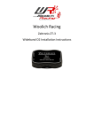
Connecting the LBPM ...................................................................................................................... 7
6)
Micro SD Card ................................................................................................................................. 7
7)
Connecting Zeitronix Wideband O2 ................................................................................................ 8
8)
Engine Data Mode (Yellow LED on) ................................................................................................ 9
9)
Data Logging Mode (Green LED on) ................................................................................................ 9
Data Logging Mode: ........................................................................................................................ 9
USB Mass Storage Mode: ................................................................................................................ 9
10) Read/Write Mode (Red LED on) ................................................................................................... 10
11) Disconnecting the LBPM ............................................................................................................... 10
12) Analogue/Digital Convertors......................................................................................................... 11
0-5v Configuration ........................................................................................................................ 13
Frequency (Rising Edge) Configuration ......................................................................................... 15
13) Bluetooth Installation ................................................................................................................... 16
Warranty ............................................................................................................................................... 18
Disclaimer.............................................................................................................................................. 18
1) Introduction
This user guide covers how to install, configure and use the Woolich Racing Log Box Pro Denso
(LBPD).
For information on how to use the Woolich Racing Tuned (WRT) software please visit our Support
Centre Video Tutorials section.
For Installation instructions and User Guides please visit the User Guides section of the Woolich
Racing web site.
For other information and frequently asked question please search the Support Centre and Woolich
Racing Forums.
2) Installing USB Drivers
The LBPM uses standard Windows USB Drivers. You do not need to download or install any special
drivers. Windows will automatically detect the LBPM when you plug it into a computer with a USB
cable. You should have the LBPM in either “Read/Write” or “Engine Data” mode for the initial
installation.
The following window should appear confirming the device has been installed.
Once installed you should see the device listed in Windows “Devices and Printers” as “Woolich
Racing USB”
3) Device Configuration
The LBPM can be configured by selecting the “Tools”->”Device Configuration” menu item within the
Woolich Racing Tuned software (WRT). You should have the LBPM in Read/Write mode (Red LED on)
or Engine Data mode (Yellow LED on). The software will attempt to automatically connect to the
LBPM, if the connection does not succeed you can click the “Connect” button to connect manually.
The following screen will be shown.
Device Type and Firmware version
The device type and firmware version information is shown in the top section of the screen.
Log Start Configuration
The Log Start Configuration allows you to configure the various parameters which affect when Data
Logging begins.
Time Delay: The number of seconds to delay before starting to log data after the device is powered
on. This setting is useful if you would like to delay data logging to prevent log files from being
created when starting the bike for short amounts of time.
Engine Running: When this option is checked the engine must be running before data will be
logged. This setting is useful to prevent logging data when the key is turned on but the engine is not
running.
RPM: The RPM that the engine must go above before data logging will begin. This setting is useful to
delay the start of data logging until the engine has been taken above the selected RPM.
Log Data to micro SD in Engine Data mode: This setting creates data logs on the LBPM when in both
Data Logging mode AND Engine Data mode. It is useful if you are using the LBPM on the dyno to
monitor engine data and you would also like to log data to be used with the Woolich Racing
AutoTune.
Only Log Analogue/Digital Data: Normally Analogue/Digitial data is only logged when there is an
active connection to Engine Data. When this setting is enabled, the LPPM will log data from the
Analogue/Digital inputs without the LBPM connected to engine data.
Once you have made changes to the LBPM configuration you should click the “Save” button to save
the settings permanently to the device.
Analogue/Digital Configuration
The LBPM has 8 channels of Analogue to Digital conversion. The Analogue/Digital Configuration
sections allows you to enable and configure the Analogue Digital Convertors. (see Analogue Digital
Convertors for more details).
4) Device Firmware Update
The LBPM firmware version is automatically checked every time you Read/Write or open the Engine
Data screen. It is also checked when you open the “Device Configuration” screen. If a newer version
of the firmware for the device is found it will be automatically updated via the built in bootloader.
If there is a problem with the firmware update process you can put the LBD into bootloader mode.
Unplug the USB cable then move the mode switch to a position half way between one of the regular
modes. Plug the USB cable back in and all of the LED’s will flash indicating the device is in bootloader
mode. You can then go to “Tools”=>”Device Configuration” and you will be prompted to select the
device type and the firmware will be updated to the latest version.
5) Connecting the LBPM
1) You need to install a Woolich Racing On Bike Harness for your bike before you can use the
LBPM. You can download model specific instructions for the On Bike Harness Installation
from our web site http://www.woolichracing.com/UserGuides.aspx
2) Once you have installed the On Bike Harness you can plug the 8 pin white Molex connector
into the On Bike Harness.
6) Micro SD Card
The LBPM comes with a micro SD card installed. This card will allow you to log approximately 80
hours of engine data. There is a slot in the plastic case to remove the micro SD card however, we do
not recommend regular removal of the micro SD card. The micro SD card contents are available
when you plug the LBPM into your computer via USB cable while in “Data Logging” mode. The micro
SD appears as an USB Mass Storage Device allowing you to access log files stored on the micro SD
card.
7) Connecting Zeitronix Wideband O2
The LBPM has a direct digital connection to a Zeitronix Wideband O2 controller. The connector is a
standard RJ12, telephone style connector. If you purchased the LBPM with the Zeitronix Wideband
O2 in a package with the installation kit you would have received the cable which allows you to
directly connect the Zeitronix to the LBPM.
The connection to the Zeitronix Wideband O2 controller is a digital connection allowing the LBPM to
receive and log AFR data at 50hz (i.e. every 20ms). There is no loss of quality for the AFR data as it is
received digitally from the Zeitronix.
To connect the Zeitronix to the LBPM plug in the RJ12 cable to both devices.
8) Engine Data Mode (Yellow LED on)
To select Engine Data Mode, move the mode switch to the left position. When in Engine Data Mode
the Yellow LED will be on. The engine data mode allows you to view real time engine data within the
WRT software in the “Engine Data” screen.
The LBPM has several statuses while in Engine Data Mode:
1) Connecting to ECU: The Green and Yellow LED’s will be solid, the Red LED will flash when
attempting to connect.
2) Connected to ECU: The Yellow LED will be soled, the Green LED will flash rapidly indicating
active communications with the ECU.
3) Connected to the ECU, Engine Data sent to PC: The Green LED will flash rapidly indicating
active communications with the ECU, the Yellow LED will flash rapidly when Engine Data is
sent to the PC via USB.
9) Data Logging Mode (Green LED on)
Data Logging Mode:
To begin data logging, make sure the USB Cable is unplugged and move the mode switch to the
centre position. The green LED should illuminate.
1) Connecting to the ECU: The Green status LED will be solid, the Red LED will flash when
attempting to connect.
2) Connected to ECU, waiting to begin Logging: Once the LBPM has connected to the ECU it will
go into wait state until the Log Start Configuration settings are met. While in wait state the
green status LED will flash rapidly indicating communications with the ECU are active.
3) Logging Data: Once the Log Start Configuration settings have been met, the LBPM will
automatically start logging data. The green LED will continue to flash rapidly. The Red LED
will flash as data is written to the micro SD card. Log files are stored with a numeric file
name starting at 0001.WRL, each new log file is named higher than the last logged file i.e.
0001.WRL, 0002.WRL etc.
USB Mass Storage Mode:
When you plug a USB cable into the LBPM data logging will stop and the device will go into
USB Mass Storage mode. The device will appear on your computer as an USB Mass Storage
Device (i.e. external hard drive). You will be able to open the LBPM like any other hard drive
on your computer and directly copy/open the Woolich Racing Log Files (.WRL files).
10) Read/Write Mode (Red LED on)
The Read/Write mode allows you to Read and Write to the ECU (i.e. Flash the ECU). To select
Read/Write Mode, move the mode selection switch to the right position. When in Read/Write mode
the Red LED will be on. The Red LED will flash when data is sent from the ECU to the computer, the
Green LED will flash when data is sent from the computer to the ECU.
Note: Not all ECU’s can be Read via the main ECU plugs, if this option is greyed out in the WRT
software it is not available for the ECU you are working with.
11) Disconnecting the LBPM
When plugged in and in Data Logging Mode, the LBPM will log engine data every time you ride your
bike. Woolich Racing recommends disconnecting and removing the LBPM when not in use.
To Disconnect the LBPM from the ECU, unplug the 8 pin Molex connector between the ECU harness
and the LBPM.
12) Analogue/Digital Convertors
The LBPM has 8 channels of Analogue/Digital convertors. These AD channels are available on the 2
RJ45 connectors. Each AD channel is paired with a Ground wire. We recommend using a twisted pair
of wires for each AD channel and Ground wire pair. You can use standard RJ45 computer network
cables for the AD input cables.
The pin assignment for the AD Channels follows
Channels 1-4 can be configured as either 0-5v input or Frequency (Rising Edge). Channels 5-8 can be
configured for 0-5v input.
Each AD channel can be routed to an Engine Data parameter for use in the Engine Data screen or in
the AutoTune screen.
Once you have selected an AD channel routing, you need to click on the “Configure” button to open
the configuration screen for the AD channel.
0-5v Configuration
When you first configure a 0-5v AD channel you will need to calibrate the AD input. This process
allows the LBPM to account for any ground offsets and will give a more accurate AD converted value.
To calibrate an AD channel:
1)
2)
3)
4)
Connect your RJ45 harness to the AD input on the LBPM
Connect the ground wire for the AD channel to the ground for the sensor to be measured.
Temporarily connect the AD channel wire to the ground wire
Click the “Calibrate” button on the 0-5v AD configuration screen
5) The software will run through a calibration process, during this process you will see a %
complete indicator on the configuration screen.
6) Once calibrated you can connect the AD wire in your harness to the sensor to be measured.
7) You can then enter the values for the 0-5v AD conversion.
a. Lower Voltage – Value
Enter the lower voltage and the converted value this corresponds to
b. Upper Voltage – Value
Enter the upper voltage and the converted value this corresponds to
8) Once you have entered the AD configuration values you should see the converted value
displayed on the configuration screen. You can update the AD settings and immediately see
the converted value update using the entered values.
9) When you have configured the AD channel click the “OK” button.
10) Click the “Save” button on the “Device Configuration” screen to save the AD configuration to
the LBPM.
Example: The following 0-5v AD configuration screen shows the AD configuration for a
Wideband O2 sensor routed to “AFR (All Cylinders)” which has a 0v AFR of 9.6 and a 5v AFR of
19.6
Frequency (Rising Edge) Configuration
You can measure a frequency input on the LBPM. The AD input will measure the rising edge of a
signal in Hz and the frequency value can be converted to other units via a Conversion Factor.
1) Enter the “Pulses per Sample” which is the number of pulses (rising edges) which correspond
to 1 sample. e.g. if you are measuring a crank angle sensor, input the number of “teeth” on
the crank angle sensor.
2) Enter the “Conversion Factor”. This conversion factor is multiplied by the frequency to give
you the final converted value. e.g. Enter 60 to convert a frequency value from a crank angle
sensor to RPM. The frequency value will be in Hz which i.e. Revs per Second, to convert this
to Revs per Minute you need to multiply by 60.
3) Once you have entered the AD Frequency parameters in the configuration screen you should
see the converted value displayed on the configuration screen. You can update the AD
settings and immediately see the converted value update using the entered values.
4) When you have configured the AD channel click the “OK” button.
5) Click the “Save” button on the “Device Configuration” screen to save the AD configuration to
the LBPM.
13) Bluetooth Installation
The LBPM has Bluetooth built in allowing you to monitor real time engine data direct from the ECU
via Bluetooth.
To configure the Bluetooth connection:
1) Open “Devices and Printers” in Windows
2) Click “Add a Device”
3) “Woolich Racing BT” will appear in the “Add a device” screen
4) Select “Woolich Racing BT” and click “Next”
5) Select “Enter the device’s pairing code”
6) Enter the paring code 1234 then click “Next”
7) You will get following message when the Woolich Racing BT has been configured.
8) The Woolich Racing BT device will appear in “Devices and Printers” And also in Device
Manager under “Ports (COM and LPT)” as “Standard Serial over Bluetooth”
Warranty
Woolich Racing Warranty obligations are limited to the terms set forth below.
Woolich Racing warrants this product against defects in material and workmanship for the period of one (1) year. The
warranty period begins with the date of original retail purchase.
This limited warranty is made only to the original end user purchaser ("you") of the product and does not extend to any
subsequent purchasers or owners of the product. The "original end user" is the first user to put the product into service in
any fashion. It is your responsibility to establish the warranty period by verifying the original purchase date.
If you discover a defect, Woolich Racing will, at its option, repair or replace this product with a new or reconditioned
product at no charge to you, provided you return it during the warranty period, with transportation charges prepaid, to
Woolich Racing. Please attach your name, address, telephone number, and a copy of the receipt from Paypal as proof of
date of original purchase, as well as a detailed description of the problem for which service is requested. You are
responsible for packing the product to be returned. If the repairs are covered by the Limited Warranty and if the product
was properly shipped to Woolich Racing, Woolich Racing will pay the return shipping charges. This warranty applies only to
Woolich Racing products. This warranty does not cover damaged resulting from accident, misuse, abuse, or neglect and/or
damage during any type of transportation resulting from improper packaging; damage to any product which has been
altered in any fashion, including damage resulting from causes other than product defects, including and not by way of
limitation, lack of technical skill, competence, or experience of the user, and/or failure to use the product in accordance
with the instructions provided in the User's Manual or Installation Manual; and service performance by an unauthorized
person or entity. Any implied warranties including fitness for use and merchantability are limited to the period of the
expressed warranty set forth above. The remedies provided under this warranty are exclusive and in lieu of all others.
Disclaimer
This product is meant for Off-Road use only and is not street legal. Owner assumes responsibility for his or her own actions
when using this product. Woolich Racing hereby expressly disclaims liability and shall not be responsible for incidental,
consequential and contingent damages or any kind or nature, including, without limitation: damages to persons or
property, whether a claim for such damages is based upon warranty, contract, tort or otherwise; damages due to or arising
out of the loss of time; or loss of profits. Woolich Racing shall not be responsible for any damages caused by the presence
of error or omission in any of its manuals, instructions or related materials.