1
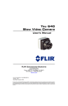
TiMi Scanning System Version 1.0 Users manual Edition September 2000 A product of a PHYTEC Technology Holding company TiMi System In this manual are descriptions for copyrighted products which are not explicitly indicated as such. The absence of the trademark () symbol does not infer that a product is not protected. Additionally, registered patents and trademarks are similarly not expressly indicated in this manual. The information in this document has been carefully checked and is believed to be entirely reliable. However, PHYTEC Meßtechnik GmbH assumes no responsibility for any inaccuracies. PHYTEC Meßtechnik GmbH neither gives any guarantee nor accepts any liability whatsoever for consequential damages resulting from the use of this manual or its associated product. PHYTEC Meßtechnik GmbH reserves the right to alter the information contained herein without prior notification and accepts no responsibility for any damages which might result. Additionally, PHYTEC Meßtechnik GmbH offers no guarantee nor accepts any liability for damages arising from the improper usage or improper installation of the hardware or software. PHYTEC Meßtechnik GmbH further reserves the right to alter the layout and/or design of the hardware without prior notification and accepts no liability for doing so. Copyright 2000 PHYTEC Meßtechnik GmbH, D-55129 Mainz. Rights including those of translation, reprint, broadcast, photomechanical or similar reproduction and storage or processing in computer systems, in whole or in part are reserved. No reproduction may occur without the express written consent from PHYTEC Meßtechnik GmbH. Address: EUROPE NORTH AMERICA PHYTEC Technologie Holding AG Robert-Koch-Str. 39 D-55129 Mainz GERMANY PHYTEC America LLC 255 Ericksen Avenue NE Bainbridge Island, WA 98110 USA Ordering +49 (800) 0749832 Information: [email protected] +1 (800) 278-9913 [email protected] Technical Support: +49 (6131) 9221-31 [email protected] +1 (800) 278-9913 [email protected] Fax: +49 (6131) 9221-33 +1 (206) 780-9135 Web Site: http://www.phytec.de http://www.phytec.com 1st Edition: September 2000 © PHYTEC Meßtechnik GmbH 2000 L-441e_1 Inhalt Introduction ..................................................................................................1 1 Short Overview ....................................................................................3 1.1 TiMi’s Working Principle ............................................................3 1.2 Working Principle of TiMi Complete System and TiMi Microscope System.......................................................................3 1.3 Equipment.....................................................................................4 2 Installation and Initial Operation ......................................................5 2.1 Installation of pciGrabber-4..........................................................5 2.1.1 Inserting the Plug-In Card ...............................................6 2.1.2 Installation of Motor Driver (only TiMi-Complete System) ............................................................................7 2.1.3 Connection of Cables after the Installation of pciGrabber-4 and the Motor Driver (only TiMiComplete System)..........................................8 2.2 Installation of Range-Adjusting Unit (only TiMi Complet System)........................................................9 2.3 Connection of Range-Adjusting Unit and Camera (only TiMi Complete System)....................................................10 2.3.1 Connection of Power Supply with Cameras VCAM 110 or VCAM 040 (only TiMi Microscope System) ...................................11 2.3.2 Installation of Cameras VCAM 110 or VCAM 040 onto a Microscope(only TiMi microscope system, microscope not included)..............12 2.4 Connecting the Camera ..............................................................13 2.4.1 S-Video-Connection ......................................................14 2.4.2 VCAM 110 (S-video) ....................................................14 2.4.3 Black/White (B/W) - Camera........................................15 2.5 How to Select and Connect an Objective ...................................15 2.5.1 The Macro Objective AO 023 .......................................16 2.5.2 The Telecentric Objective AO 024................................17 2.6 Installation of Driver and Software ............................................18 2.6.1 Installation of TiMi Software ........................................18 3 The TiMi Program ............................................................................19 3.1 Structure......................................................................................19 3.2 The Program’s Options...............................................................19 3.2.1 Start of the Program.......................................................19 3.2.2 TiMi’s main screen........................................................20 3.2.3 Taking Pictures Manually and Automatically..............24 3.2.4 Taking Pictures of an ‘In-Depth’ Object .......................25 PHYTEC Meßtechnik GmbH 2000 L-441e_1 TiMi System 3.2.5 Presentation of a Three-Dimensional Synthetic Object ............................................................ 30 3.2.6 Setting and Displaying a Scale...................................... 30 3.2.7 The Program’s Further Options .................................... 33 3.3 Summary of the Allocation of Keys........................................... 33 3.4 Programming of Camera VCAM 110 ........................................ 33 4 System Maintenance ......................................................................... 34 4.1 Maintenance of Camera.............................................................. 34 4.2 Maintenance of Objectives......................................................... 34 4.3 Maintenance of Macro Scanning Unit ....................................... 34 5 Solving Problems............................................................................... 35 5.1 Distorted ‘In-Depth’ Pictures ..................................................... 35 5.2 Video Signal Is Not Recognized ................................................ 35 5.3 Motor Does Not Start ................................................................. 36 5.4 Calibration Fails ......................................................................... 36 5.5 Low Picture Quality ................................................................... 37 5.6 Further Interferences .................................................................. 37 6 Technical Data................................................................................... 39 6.1 Camera........................................................................................ 39 6.2 pciGrabber-4............................................................................... 39 6.3 Macro Scanning Unit (TiMi Complete System) ........................ 40 6.4 Software...................................................................................... 41 Attachment A ............................................................................................. 43 A.1 Scope of Supply for TiMi Complete System (TiMi K) / TiMi Microscope System (TiMi M)......................... 43 Index............................................................................................................ 47 Bildverzeichnis Figure 1: Connection of pciGrabber-4 and Motor Driver ......................... 7 Figure 2: Connection of cables at PC’s-back ............................................ 8 Figure 3: Installation of Column onto Object Table.................................. 9 Figure 4: Installation of Range-Adjusting Unit onto Column................... 9 Figure 5: Connection of Cables and Range-Adjusting Unit.................... 10 Figure 6: Connection of Camera and Power Supply ............................... 11 Figure 7: Installation of Camera onto Microscope .................................. 12 Figure 8: Connectors of pciGrabber-4..................................................... 13 © PHYTEC Meßtechnik GmbH 2000 L-441e_1 Inhalt Figure 9: Camera Pin Assignment (VCAM 110) ....................................14 Figure 10: Cables VKAB-010 and VKAB-011 .........................................15 Figure 11: Macro Objective AO 023 .........................................................16 Figure 12: Telecentric Objective AO 024..................................................17 Figure 13: Start Dialo.................................................................................19 Figure 14: Calibration ................................................................................20 Figure 15: TiMi’s main screen...................................................................20 Figure 16: Settings, Options.......................................................................24 Figure 17: Filter and Image Settings..........................................................25 Figure 18: Filter Settings............................................................................27 Figure 19: Example for the Presentation of a Three-Dimensional Synthetic Object .......................................................................30 Figure 20: Menu Dia1og 1, Set Scale ........................................................31 Figure 21: Menu Dialog 2, Set Scale .........................................................31 Figure 22: Menu Dialog 3, Set Scale .........................................................31 Figure 23: Menu Dialog 4, Set Scale .........................................................31 Figure 24: Menu Dialog 5, Set Scale .........................................................32 Figure 25: Menu Dialog 6, Set Scale .........................................................32 Figure 26: Menu Dialog 7, Set Scale .........................................................32 Figure 27: Distorted Picture.......................................................................35 Figure 28: Settings .....................................................................................36 PHYTEC Meßtechnik GmbH 2000 L-441e_1 TiMi System © PHYTEC Meßtechnik GmbH 2000 L-441e_1 Introduction Introduction PHYTEC does not accept any liability for damages arising from improper usage or improper installation of the device or the software. PHYTEC can also not be made responsible for statements or interpretations arising from possibly faulty measuring results. This especially concerns the medical and the scientific sector as well as quality control and quality assurance. The limitation of liability applies to all liabilities no matter what legal justification. This only exempts liabilities covered by the law on product liability, as well as features for which liability has been granted and in so far as this assurance had been intended to protect the customer from the damage suffered. In the case of liability on account of a neither willful nor negligent violation of fundamental contractual commitments, liability is limited to the extent of damage that in the given case can be typically forecasted. There is no liability on guarantee (cf. § 538 para.1 1. Art. Civil Code (German law)). The user is obliged to take appropriate precaution for the protection of data and other software. Backups should be made at customary intervals. Construction and programming can be altered without prior notification. In such a case, however, the customer cannot deduce any claims concerning systems already acquired. All other regulations applicable are laid down in PHYTEC’S general terms of business. For additional information, please contact: EUROPA NORD AMERIKA Address: PHYTEC Technologie Holding AG Robert-Koch-Str. 39 D-55129 Mainz GERMANY PHYTEC America LLC 255 Ericksen Avenue NE Bainbridge Island, WA 98110 USA Web Seite: http://www.phytec.de http://www.phytec.com e-mail: [email protected] [email protected] Tel.: +49 (6131) 9221-0 +1 (800) 278-9913 Fax: +49 (6131) 9221-33 +1 (206) 780-9135 PHYTEC Meßtechnik GmbH 2000 L-441e_1 1 TiMi System 2 © PHYTEC Meßtechnik GmbH 2000 L-441e_1 Short Overview 1 Short Overview 1.1 TiMi’s Working Principle TiMi facilitates the presentation of three-dimensional objects sharply focused, exceeding the limits of optical focus depth by making use of digital image processing. To achieve thisTiMi first filters the regions of sharp focus from a number of single pictures which are taken with a microscope or a macro scanning unit (fitted with a video camera) along the optical axis. These are saved and finally assembled to generate one single picture of high ‘in-depth’ quality.TiMi could thus be said to be performing a kind of optical tomography. 1.2 Working Principle of TiMi Complete System and TiMi Microscope System To take a picture extending the optical focus depth normally possible the following steps have to be taken: 1. 2. 3. 4. 5. 6. 7. Taking the picture Saving the image Separating elements of sharp focus from unfocused ones Saving elements of sharp focus Focusing a new level Taking another picture Assembling all elements of sharp focus from all levels. PHYTEC Meßtechnik GmbH 2000 L-441e_1 3 TiMi System The following components are needed: • • • • • video camera unit for focusing and taking pictures of single levels image buffer image processing The video camera used is PHYTEC’s camera VCAM 110 (VCAM 040). This camera is available with both TiMi systems. An ordinary microscope can serve as focusing unit if it does feature a C-mount. In this variant the TiMi program asks the user to choose a new level manually during the process of taking the ‘in-depth’-picture. A picture taking system which facilitates an automatized process of taking the ‘in-depth’-picture is available for the macro field. In that case the RAM of the PC used to operate TiMi serves as an image buffer, whereas the TiMi program is responsible for image processing as well as for addressing the macro scanning unit. 1.3 Equipment The following equipment is necessary for the operation of the TiMi complete system: telecentric objective: • AO 024 Computar 1:2,8 / 55 mm telecentric or macro objective system with a set of spacer rings: • AO 023 Schneider 1:2,8 / 50 mm Componon-S macro objective The following equipment serves the extension of the range of application: • black and white - camera VCAM 040 The above mentioned equipment is available from PHYTEC. 4 © PHYTEC Meßtechnik GmbH 2000 L-441e_1 Installation and Initial Operation 2 Installation and Initial Operation 2.1 Installation of pciGrabber-4 Please pay attention to the specified operation directives of the pciGrabber-4. Before start up please read the manual carefully. • The pciGrabber-4 is designed for the digitalization of video signals from standard TV-cameras. The following signals can be processed: signals from composite-video cameras which are in accordance with norms CCIR B, G, H, I and sub standards CCIR B, G, H, I/PAL. Additionally signals in compliance with CCIR M/NTSC can be applied. Following the S-video standard the luma and chroma signal of the camera signal can be supplied separately (channel 9 only). The digitalization is achieved in real time. The image data is transfered via the PCI-bus of the PC. The transfer rate corresponds to the access time specified for the PCI master slot. The effective transfer rate must be corresponding to the volume of image data, otherwise information might be lost. • The pciGrabber-4 is for use in standard PCs, i.e. usual office PCs. The pciGrabber-4 has to be plugged into a master PCI-slot. The Grabber must have a reliable connection with the computer’s case and the Ground (PE). The board is designed to operate in a dry and dustless environment. For applications in connection with machinery, in an industrial environment or in devices differing from the usual PC constellation please consider additional protective arrangements especially against radio interference and safety hazards. • The use of the device in security relevant areas, i.e. for aviation and space and for nuclear or military purposes requires our verification and consent. • In case of commercial use respective safety rules have to be complied with. • Before initial operation it generally must be ensured that the device is suitable for the chosen application and location. If in doubt, it is urgently recommended to check with an expert or the manufacturer. PHYTEC Meßtechnik GmbH 2000 L-441e_1 5 TiMi System • The product has to be protected from hard shocks and vibrations. If necessary springs or a padding have to be provided for. This should not, however, prevent proper ventilation of the device. • If in need of repair this may only be done by an expert using original components. For the installation of the Grabber, only use tested and approved cables. Only radio shielded cables should be utilized. 2.1.1 Inserting the Plug-In Card • Shut down the computer or disconnect the power source. Make sure that no voltage is applied to the device! • Open the PC’s case. • Choose a free PCI slot. Make sure that it is a master slot. In the case of most mother boards all PCI-slots are master slots. Slave slots are normally marked accordingly. If in doubt, refer to the manual of your PC or your mother board. Attention: If the pciGrabber-4 is installed in a slave slot, the system will possibly not be able to boot. The pciGrabber-4 will in any case not work correctly. • Remove the back panel bracket from the PC’s case. • Carefully insert the pciGrabber-4 into the appropriate slot. Make sure that the card’s golden contact lead corresponds with the contacts of the expansion-card slot. Push in the card very carefully. Make sure that the card is inserted properly and that no neighboring contacts are short-circuited. The pciGrabber-4 is suitable for the 5 V PCI BUS. These are coded by a corresponding notch at the PCI slot. The card cannot be inserted into slots that only support 3,3 V systems. • Fix the card to the case with the screw of the back panel bracket. • If no motor driver is used, close the PC’s case. • While the PC is booting, the PCI-BIOS of the computer will recognize the new card. This is shown by a corresponding message. 6 © PHYTEC Meßtechnik GmbH 2000 L-441e_1 Installation and Initial Operation • To control functioning, we recommend the use of the demo software on the disk included. (shut down PC only after section 2.1.3) 2.1.2 Installation of Motor Driver (only TiMi-Complete System) The motor driver allows to address the range-adjusting unit directly via the extension port of the pciGrabber-4. Thus no further interface of the PC is occupied. For installation take the following steps: • Choose a free space in the PC’s back panel, if possible close to the pciGrabber-4. An ISA or PCI-slot is not necessary. Remember, however, that if the motor driver is mounted to the back panel of an ISA or PCI-slot, the slot cannot take on another plug-in card. • Fix the motor driver board to the back panel with the screw provided. • Connect the motor driver with the pciGrabber-4 via the twentypole ribbon cable. The red cable conductor has to match the markings on both boards, i.e. X2 on the motor driver and X6 on pciGrabber-4. After that please connect the motor driver with the power supply ( marking X1 ), (see Figure 1). • Close the PC’s case again. X1 Figure 1: Connection of pciGrabber-4 and Motor Driver PHYTEC Meßtechnik GmbH 2000 L-441e_1 7 TiMi System 2.1.3 Connection of Cables after the Installation of pciGrabber-4 and the Motor Driver (only TiMi Complete System) After the installation of the pciGrabber-4 and the motor driver, please connect the S-video cable with the pciGrabber-4 and the supply cable with the motor driver at the PC’s back. Figure 2: 8 Connection of cables at PC’s-back © PHYTEC Meßtechnik GmbH 2000 L-441e_1 Installation and Initial Operation 2.2 Installation of Range-Adjusting Unit (only TiMi Complete System) For reasons of packaging the range-adjusting unit, the column and the object table are not preinstalled. Before initial operation the column has to be mounted on the object table with an M6-screw and a washer (both included with the column). × Figure 3: underside Installation of Column onto Object Table After that the range-adjusting unit can be installed and fixed with the lock screw in such a way that the carriage can still be moved, but does not slip by itself. carriage lock screw Figure 4: Installation of Range-Adjusting Unit onto Column PHYTEC Meßtechnik GmbH 2000 L-441e_1 9 TiMi System 2.3 Connection of Range-Adjusting Unit and Camera (only TiMi Complete System) The range-adjusting unit is operated by the PC. This is done via the supply cable, which connects the energy unit with the motor driver. To prevent the supply cable from accidentally slipping out of the socket, fix it to the socket with its knurled screws. After that please connect the S-video cable and the control cable. Figure 5: 10 Connection of Cables and Range-Adjusting Unit © PHYTEC Meßtechnik GmbH 2000 L-441e_1 Installation and Initial Operation 2.3.1 Connection of Power Supply with Cameras VCAM 110 or VCAM 040 (only TiMi Microscope System) Connect the cables of the plug-in power supply included with the sockets marked – DC 12 V + (the black cable goes into the black socket and the red one into the red socket). Ô red cable Figure 6: Connection of Camera and Power Supply PHYTEC Meßtechnik GmbH 2000 L-441e_1 11 TiMi System 2.3.2 Installation of Cameras VCAM 110 or VCAM 040 onto a Microscope (only TiMi microscope system, microscope not included) Install the camera with the help of your microscope’s camera mount, maybe with a C-mount adapter (M29x1) from the microscope’s equipment. Figure 7: 12 Installation of Camera onto Microscope © PHYTEC Meßtechnik GmbH 2000 L-441e_1 Installation and Initial Operation 2.4 Connecting the Camera The pciGrabber-4 does feature 9 channels for video sources. TiMi software is therefore able to process image data from different cameras. To be able to do this the user can set the channel needed respectively (see paragraph 3.2.3 “Taking Pictures Manually and Automatically”). One and the same software can thus for example be used to address the macro scanning unit (TiMi complete system) as well as for operating a manual microscope. Depending on the camera (S-video, FBAS-color or FBAS-black/white) there are different possibilities of connecting the components which are explained in the following. Figure 8: Connectors of pciGrabber-4 PHYTEC Meßtechnik GmbH 2000 L-441e_1 13 TiMi System 2.4.1 S-Video-Connection An S-video signal can be applied to a four-pin Mini-DIN plug (X3). The advantage of this system is the separate conduct of brightness and color signal. This prevents disturbing Moiréeffects for fine image structures and improves the resolution of the color image. The composite-input 9 and the S-video-socket cannot be used simultaneously! 2.4.2 VCAM 110 (S-video) The camera as well as the pciGrabber-4 both have one four-pin MiniDIN socket,each which serves the connection via the S-video cable. Figure 9: 14 Camera Pin Assignment (VCAM 110) © PHYTEC Meßtechnik GmbH 2000 L-441e_1 Installation and Initial Operation 2.4.3 Black/White (B/W) - Camera The black/white camera does feature a BNC-connector (video out). It can thus be connected via the BNC cable to one of the two 15-pole sub-D sockets of the pciGrabber-4. Cables VKAB-010 or VKAB-011 are available from PHYTEC. Figure 10: Cables VKAB-010 and VKAB-011 2.5 How to Select and Connect an Objective To connect an objective please remove the camera’s protective cover. The objective can now be screwed in via the C-mount connector. The diameter of the housing of the objective may not exceed 55 mm. It is urgently recommended to use a special close-range objective. Conventional systems are not suitable for taking pictures at short distances (this also applies to the use of spacer rings, macro lenses or other adapters) and only supply a very unsatisfactory picture quality. This is not sufficient for the generation of ‘in-depth’ pictures. The focal distance of the chosen objective may also not go below 50 mm! Both objectives AO 024 and AO 023 recommended for TiMi by PHYTEC meet these requirements. PHYTEC Meßtechnik GmbH 2000 L-441e_1 15 TiMi System 2.5.1 The Macro Objective AO 023 Figure 11: Macro Objective AO 023 The macro objective serves the photographing of very small objects using a distance of just a few centimeters while taking the picture. Too large a distance can lead to distortions of the ‘in-depth’ picture on account of the optical effect. To still be able to take such pictures, a telecentric objective has to be used (see paragraph 5.1 “Distorted ‘InDepth’ Pictures”). 16 © PHYTEC Meßtechnik GmbH 2000 L-441e_1 Installation and Initial Operation 2.5.2 The Telecentric Objective AO 024 Figure 12: Telecentric Objective AO 024 A telecentric objective can reproduce objects which are at different distances at roughly the same scale. If a distance of more than 10 - 15 cm is desired use of this objective is obligatory. PHYTEC Meßtechnik GmbH 2000 L-441e_1 17 TiMi System 2.6 Installation of Driver and Software To install the driver and the software start Windows’ setup.exe with the help of the driver CD included. Choose the setup menu execute and type in A:\setup. Press <Enter>. Follow the setup program’s instructions or start the program via the folder my workplace, disk drive a:. Only Windows 95/98: After the installation of the pciGrabber-4 and the motor driver, Windows 95/98 automatically asks for the driver CD. Put the driver CD into disk drive a: and follow the menu instructions of Windows 95/98. 2.6.1 Installation of TiMi Software Put the set up disk/CD into disk drive a: and start setup.exe. To do this choose execute in the start up menu and type in A:\setup. Press <Enter>. Follow the instructions of the setup program. The system is now ready for use. 18 © PHYTEC Meßtechnik GmbH 2000 L-441e_1 TiMi Program 3 The TiMi Program 3.1 Structure TiMi software does have two fundamental tasks. On the one hand it facilitates the electric motor-driven level control (only TiMi complete system). On the other hand it collects pictures and analyses them automatically to facilitate generating an ‘in-depth’ picture. The user’s job is to illuminate the object of which the picture is to be taken, to determine the depth of the scanning region and to classify the object. 3.2 The Program’s Options 3.2.1 Start of the Program As customary with Windows the program is started via start, programs, TiMi or a desktop link. After starting the program a start dialog (see Figure 13) appears. The lower part of the start dialog shows if and at which channel a video signal has been found. Figure 13: Start Dialo PHYTEC Meßtechnik GmbH 2000 L-441e_1 19 TiMi System If necessary the position of the motor (see Figure 14) is calibrated. In this case the motor shortly starts. If no motor is connected, the program waits a few seconds before informing the user that no motor has been found. The program is now in the manual mode. The automatic level control (see paragraph 3.2.3) can easily be reactivated. If this is not done, however, the program will in future not try to find the motor. Figure 14: Calibration 3.2.2 TiMi’s main screen After starting TiMi the main screen appears. ➀ ➁ ➂ ➆ ➄ ➃ ➅ Figure 15: 20 ➇ TiMi’s main screen © PHYTEC Meßtechnik GmbH 2000 L-441e_1 TiMi Program The components of TiMi’s main screen are described in the following: ➀ window title All TiMi-windows feature a window title at their upper margin. ➁ menu bar The menu bar is below the window title. This is where all TiMi menus can be found. Click on the respective title and the menu items appear below. ➂ icon bar The icon bar contains the most important commands from the menu bar in the form of icons. This allows to access these commands directly (see paragraph 3.2.2.1 “Icons of icon bar”). ➃ work space The work space is the large area below the icon bar. Active windows, the live image and the filter window appear here. ➄ live picture Example of a live image (board). ➅ Window for presentation Shows bitmaps. Figure 15 for example shows an ‘in-depth’ picture (board). ➆ filter window The filter window contains all necessary settings for filtering. The complete description of these options is found in paragraph 3.2.4 “Taking Pictures of an ‘In-Depth’ Object”. ➇ status bar The status bar informs about the time needed to analyze each picture, the current state of the scanning process and the time remaining. PHYTEC Meßtechnik GmbH 2000 L-441e_1 21 TiMi System 3.2.2.1 Icons of icon bar Load/save picture Loads an already existing bitmap or saves one just taken. Load/save image and filter Saves/loads accompanying filtering information connected with the image saved or loaded. The name of the filter is the name of the bitmap associated. Load/save three-dimensional synthetic object Loads or saves a calculated three-dimensional synthetic object. Insert scale Allows to insert a scale into whatever space desired in the picture and then opens a file dialog. Choose a file to be able to load the corresponding scale file (also see paragraph 3.2.7 “The Program’s Further Options”). Measurement of a distance in the picture This option facilitates the measurement of a distance in the picture. A file dialog is opened. EMERGENCY STOP EMERGENCY STOP: Interrupts the scanning process at once. 22 © PHYTEC Meßtechnik GmbH 2000 L-441e_1 TiMi Program Filter- and image settings This option opens the filter and image settings window (details see paragraph 3.2.4, “Taking Pictures of an ‘InDepth’ Object”, 1. Selection of scanning region). Taking of a single image This option generates a still picture. Live image Shows the current live image as a full frame picture. Present current three-dimensional synthetic object Opens the current three-dimensional synthetic object window. Copy Copies the current result window into the clipboard. Start/stop ‘in-depth’ picture The scanning process can be started here and if necessary broken off. If the scanning process has gone through to the end, the presentation of results follows automatically. Bitmap enlarge /reduce/orginal size With this icon a bitmap can be enlarged/reduced by a specific factor or set back to original size. PHYTEC Meßtechnik GmbH 2000 L-441e_1 23 TiMi System 3.2.3 Taking Pictures Manually and Automatically In connection with the macro scanning unit (TiMi-complete system) TiMi supports the automatic positioning at different levels for picture taking. It also facilitates the manual choice of single levels, for example if ‘in-depth’ pictures are produced with the help of ordinary microscopes. To prepare the program for one of the two ways to proceed, please choose menu settings. A dialog then appears (see Figure 16) which allows to enter different settings. The dialog offers two choices (radio buttons), one saying automatic focusing the other manual focusing, one for the electric motor-driven the other for manual positioning. Figure 16: Settings, Options Short instruction: display: channel: Step size: 24 switch on/off automatic insertions of the program’s short instruction if there is an S-video camera connected, it is preset to channel 9. the step size of the stepping motor is entered via the menu filter and image settings (see paragraph 3.2.4.) To achieve as fine a resolution as possible for the presentation of the three-dimensional synthetic object, use as high as possible a number of picture taking levels (>40). © PHYTEC Meßtechnik GmbH 2000 L-441e_1 TiMi Program horizontal graticule: Lines: Background: amount of gridsheet system lines by line amplitude during the presentation of three-dimensional synthetic objects. The higher the factor, the more detailed the presentation. Opens a menu window for color choice. Opens a menu window for color choice. 3.2.4 Taking Pictures of an ‘In-Depth’ Object Enter a few important parameters before starting the picture taking process (or start the picture taking process directly via the initial settings). It has to be defined: 1. which region is of interest for the picture, 2. to which object type your object belongs and 3. how many picture taking levels should be used. 1.Choosing the scanning region: Choose menu title image, image and filter settings. A window then opens showing a small live image (see Figure 17). To the right of it there are a few options which allow to influence the parameters of the image and the macro scanning unit (deactivated in the manual mode). Influence brightness, contrast and color adjustment with the help of these options. The button <reset> is for returning to the standard setting. These include the options of camera positioning. Figure 17: Filter and Image Settings PHYTEC Meßtechnik GmbH 2000 L-441e_1 25 TiMi System The procedure works as follows: First the uppermost level is properly focused manually with the help of the camera objective (this is not done by just positioning the camera!). After this the camera can be moved with the buttons featuring the little arrows until the last desired level is reached. The arrows on the right hand move one whole step size and the fragmented arrows on the left hand move by 1/10 step size. To return to the start use the button with the upturned double arrow. If the final position has been reached to one’s satisfaction, shut off the input with the buttonset last level. The camera in this case returns to the starting point automatically. To reset the final position previously chosen use the button showing the double arrow turned downwards. The camera position can also be operated via the keyboard: = Picture Ç =Ç =Æ = Picture Æ = Pos 1 = Enter Corrections can simply be made by moving again and renewed confirmation with the button last level. If necessary this procedure can be repeated as often as wanted. The camera icon at the right margin in a bar normally green moves parallel to the real camera. If this bar turns yellow or even red during the setting, the end of the scanning region has been reached. The window can but does not have to be closed before the start of the scanning process. 2.Selection of class of object (Filter settings): a) Edit field image Enter the desired amount of picture taking levels. A suitable factor is suggested by the software. The setting is uncritical. The factor should, however, not be higher than 5. Good presentations of three-dimensional synthetic objects very often need more than 40 levels. More than 80 picture taking levels generally do not make sense. If the resolution of steps of the range-adjusting unit falls below, the amount of levels is automatically reduced and updated in the edit field. As the duration of the scanning process also depends on the amount of levels, it should be kept as low as possible. 26 © PHYTEC Meßtechnik GmbH 2000 L-441e_1 TiMi Program b) Edit field region This setting defines the region to be scanned (in mm). It can comfortably be entered and displayed with the live image. c) Edit field object type Object type settings are filter settings that have been defined beforehand for the most important types of objects. Figure 18: Filter Settings PHYTEC Meßtechnik GmbH 2000 L-441e_1 27 TiMi System They are subdivided as follows: • low-contrast (low-contrast): This setting is for objects with smooth surfaces with little or no structure. In this case much information from the respective surroundings has to be included. This setting does need much CPU-time. • smooth: This setting handles objects with little structure but higher contrast. In this case too some CPU-time is needed but less than with the setting low-contrast. • Insect: Choose this setting if the object is delicate, but does also have smooth surfaces as in the case of insects. This needs a little less CPU-time. • single color/light: Light or single color surfaces are filtered with this setting. It works relatively fast. • rough/standard: Use this setting if the object features clearly visible color structures or surface roughness. The operating speed is even higher. • Preview: This is the quickest filtering possibility and serves to control the settings. The result contains all image data, but shows clearly visible graticule structures in the case of high contrast regions. • Input: This option enlarges the tool window. It allows to change the filtering parameters oneself. The setting of the filter last defined serves as preset option. The selection of the right setting is quite uncritical. If the result should not be satisfying, choose the next higher object type. As a rule principally all objects can be filtered 28 © PHYTEC Meßtechnik GmbH 2000 L-441e_1 TiMi Program with the setting smooth, but shiny objects can hardly ever be filtered with rough/standard. The more images are made, the more secure the filter works as it can rely on a lot of data. • noise reduction: Reduces noise of image data. • low contrast: Improves the result with low-contrast objects. • Pixel: The factor determines the amount of pixel by with of matrix examined at the same time. • Block: Size of the region of interest in pixel. If the object does have little structure, the result is improved by an enlarged region of interest. Open-Icon and save-icon: Saves all filter settings, but also the accompanying camera parameters (see paragraph 3.2.4 “Taking Pictures of an ‘InDepth’ Object”, 2.a) live image) as an ASCII file. They can thus be retrieved later. PHYTEC Meßtechnik GmbH 2000 L-441e_1 29 TiMi System 3.2.5 Presentation of a Three-Dimensional Synthetic Object To achieve as fine a resolution as possible for the presentation of the three-dimensional synthetic object, use as high a number of picture taking levels as possible (>40). The presentation of the three-dimensional synthetic object (see Figure 19) can be rotated in the direction of all three space coordinates with the help of the cursers. Figure 19: Example for the Presentation of a Three-Dimensional Synthetic Object 3.2.6 Setting and Displaying a Scale For dimensional control purposes it is very often desirable or even necessary to indicate a comparison scale with the picture. TiMi offers the possibility to insert a previously scaled scale wherever wanted in the picture. The scale is then be saved and included in the picture. To produce a comparison scale, please choose menu title Options, scale set. A window will appear. Follow the instructions (see Figure 20 to Figure 26). All choices made in the following can be undone with the right mouse key. 30 © PHYTEC Meßtechnik GmbH 2000 L-441e_1 TiMi Program Figure 20: Menu Dia1og 1, Set Scale Note: Do only focus by using the BUTTONS FEATURING THE ARROWS! Do not use the objective for focusing as this changes the scale of reproduction. Figure 21: Menu Dialog 2, Set Scale Figure 22: Menu Dialog 3, Set Scale Figure 23: Menu Dialog 4, Set Scale PHYTEC Meßtechnik GmbH 2000 L-441e_1 31 TiMi System Figure 24: Menu Dialog 5, Set Scale Figure 25: Menu Dialog 6, Set Scale Figure 26: Menu Dialog 7, Set Scale 32 © PHYTEC Meßtechnik GmbH 2000 L-441e_1 TiMi Program 3.2.7 The Program’s Further Options Search video signal: To search the video signal choose menu title file, search video signal or <F2>. Calibration of range-adjusting unit: To start calibrating the starting position of the range-adjusting unit, choose menu title file, calibrate or <F3>. 3.3 Summary of the Allocation of Keys <F2> search video signal <F3> calibration of range-adjusting unit <F4> measurement of distance <F5> set scale<F6> taking of a single image <F7> live image <F8> filter and image settings <F9> start picture taking process <F10> stop picture taking process 3.4 Programming of Camera VCAM 110 See VCAM110’s driver software. The driver software allows to program the camera for each situation individually. PHYTEC Meßtechnik GmbH 2000 L-441e_1 33 TiMi System 4 System Maintenance 4.1 Maintenance of Camera No dust or other dirt should be allowed to enter the camera’s housing and dirty the CCD-Chip. The surface of the CCD-chip may not be touched. If, however, the surface of the CCD-chip is dirtied, this can be removed with compressed air (available with photo equipment). 4.2 Maintenance of Objectives Pay attention to not exposing the outer surfaces of the lenses to mechanical use or dirt as they are covered with a sensitive antireflection layer. To clean the surfaces of dust compressed air is recommended. Other dirt can be removed with a soft cotton cloth. Do not in any case use cleansing agents! Light dirt or dust does in most cases not worsen the picture quality. 4.3 Maintenance of Macro Scanning Unit The macro scanning unit is maintenance-free. Do not ever oil it as this will permanently damage TiMi M. Use a soft cotton cloth to clean the surfaces of dust and other dirt. Do not in any case use cleansing agents. Do not try to repair the device yourself. This leads to the loss of your entitlement to liability. 34 © PHYTEC Meßtechnik GmbH 2000 L-441e_1 Solving Problems 5 Solving Problems 5.1 Distorted ‘In-Depth’ Pictures If the ‘in-depth’ picture contains structures similar to the ones in the following picture, Figure 27: Distorted Picture this is not a fault of the system. It can be put down to a particular optical effect which appears the stronger, if an objective which has not been corrected telecentrically is used while at the same time too small a reproduction scale has been chosen. To prevent this we recommend the use of the telecentric objective AO 024 available from PHYTEC. 5.2 Video Signal Is Not Recognized • Check menu title Options, settings to see if the correct channel has been chosen. • Check the correct installation of all cables. PHYTEC Meßtechnik GmbH 2000 L-441e_1 35 TiMi System 5.3 Motor Does Not Start • Check menu title Options, settings to see if the option electric motor-driven focusing has been chosen. Figure 28: • Settings Check the correct installation of the connection of the rangeadjusting unit with the motor driver, as well as the one between the motor driver and the pciGrabber-4. 5.4 Calibration Fails If at the start of the program or during the process the message "Calibration does not work" appears and the motor has not moved this defect can only be dealt with by PHYTEC. If this should happen, please send in the device with a corresponding description of the defect to have it repaired. If the motor has just not moved, please check if everything has been correctly installed, i.e. the connection between the range-adjusting unit and the motor driver or between the motor driver and pciGrabber-4. 36 © PHYTEC Meßtechnik GmbH 2000 L-441e_1 Solving Problems 5.5 Low Picture Quality If the picture contains unfocused regions or stains which cannot be put down to the object, this is a sign of dirt on the surface of the CCDchip. (This is especially noticeable where highly enlarged microscopic pictures are concerned). Cleaning the surface of the CCD-chip is in this case necessary. Proceed as follows: Remove the objective from the camera or take the camera off the microscope. Remove dust with compressed air. Remember that the interfering dust is very often not be visible to your bare eye. Do not in any case use cloths or similar things for cleaning as they very often leave even more dust. Lightly dirtied objectives do normally not lead to a worse picture quality in the micro and macro field. If there are further optical elements in the light path (for example extension tubes where microscopes are concerned), dirt on their surface can also appear in the picture. If the picture is strongly noisy or low-contrast, the objective’s iris is either closed too far or the object is too weakly illuminated or the camera (in manual mode) has been adjusted too insensitively (see paragraph “3.4 Programming of Camera VCAM 110”). 5.6 Further Interferences The digitalized image shows streaks or stripes: • The camera’s S-video line is defect (check shielding). • A Ground loop might be caused via an additional Ground connection between PC and camera, causing a mains hum . Check, if ground loops or power supply cause a mains hum (only TiMimicroscope system). PHYTEC Meßtechnik GmbH 2000 L-441e_1 37 TiMi System No image is digitalized at the S-video input : • Has channel 9 been selected? • Has the S-video input been correctly connected? • Has TiMi been correctly configured to S-video operation? For S-video operation the image is black/white with strong color disturbances: • Is the chroma signal properly connected? • Is this really an S-video source? • Is no further image source connected with channel 9? The image is low-contrast/ too light /too dark: • Check settings brightness, contrast, etc. Notes: 38 © PHYTEC Meßtechnik GmbH 2000 L-441e_1 Technical Data 6 Technical Data 6.1 Camera max. current: 500 mA 6.2 pciGrabber-4 Dimensions: Data bus: 180 x 180 x 20 mm incl. front screen and slot PCI-Bus 5 V, master slot required (PCI.Rev. 2.1 compliant) Power supply: +12 V* ( 210 mA idle, 300 mA digitalizing), -12 V (40 mA) (are supplied by the PCI-Bus) Inputs: 9 composite video inputs, 1 Vss, 1 S-video input (0,7 Vss / 0,3 Vss, requires composite-channel 9) Video formats: PAL (B,D,G,H,I), NTSC (M), SECAM Synchronization: Composite-Sync or Sync on Y-Signal resp. external synchronization not possible Data formats: 16 Mio. colors: RGB32, RGB24, YCrCb 4:2:2, YCrCb 4:1:1, 64.000 colors: RGB16, 32.000 colors: RGB15, 256 Grey values: Y8 Grey Scale Image resolution:maximum 720 x 576 Pixels (PAL), resolution freely scalable in X- and Y-direction up to 14:1 Image recording: Field: 20 ms, Full frame: 40 ms, Image transfer to main memory in real time (Busmaster-Transfer) Applied resources: 4 kByte main memory (register region) /INTA (optional) PHYTEC Meßtechnik GmbH 2000 L-441e_1 39 TiMi System Image: Image storage: Ports: Connectors: AGC (selectable), Gamma correction (selectable), Brightness (+/- 50 %), Contrast (0% ... 235 %), Color saturation (U: 0...201 %, V: 0...283 %), Hue (+/- 90°, only for NTSC) 630 Byte FIFO on board, Real-Time storage in the PC- main memory, even-/odd-memory separate or common whole frame memory (selectable) 12-bit parallel-I/O (multi purpose), I²C- interface (master), Voltage levels: Outputs low VOL= 2.5 V...5.0 V (IOL= 6 mA), Outputs high VOHmax= 0.4 V (IOH = -2 mA), Inputs low VIL = 0 V...0.8 V, Inputs high VIH = 2.0 V...5.0 V 2 x HD-DB-15 sockets: Socket 1: five composite inputs, Socket 2: four composite inputs and, a 12 V-DC-output for camera-supply (400 mA max.) MINI-DIN-socket (S-video-input) 6.3 Macro Scanning Unit (TiMi Complete System) • • • • • • • • • • 40 max. object height: current (max. power): supply voltage: max. heaving force: height: object table: Ground: color: fuse: usable stativ diameter: 51 mm 300 mA 12 V (aus PC) 3N ca.380 mm 300 mm x 250 mm ca. 5 kg RAL 1013 1,6 A T 30 mm © PHYTEC Meßtechnik GmbH 2000 L-441e_1 Technical Data 6.4 Software Minimum requirements of the system: • • • • • • CPU: RAM: Main board: HDD: Graphic: OS: Pentium 66 MHz 16 MB PCI 5 MB free memory 800 x 600 x 16-bit-color Windows 95 Recommended: • • • • • • CPU: RAM: Mainboard: HDD: Graphic: OS: Pentium 133 MHz >32 MB PCI 30 MB free memory (to be able to save results) at least1024 x 768 x 24-bit-color Windows 95/98/NT4.0 PHYTEC Meßtechnik GmbH 2000 L-441e_1 41 TiMi System 42 © PHYTEC Meßtechnik GmbH 2000 L-441e_1 Attachment A Attachment A A.1 Scope of Supply for TiMi Complete System (TiMi K) / TiMi Microscope System (TiMi M) VPK–004 Complete System Color: • • • • • • • • • pciGrabber-4 Video Camera VCAM 110 Software (Driver and Software) S-video Cable Interface Cable User’s Manual Macro Scanning Unit Stativ Motor Driver VPK004-x1 Complete System Color (without stativ): • • • • • • • • pciGrabber-4 Video Camera VCAM 110 Software (Driver and Software) S-video Cable Interface Cable User’s Manual Macro Scanning Unit Motor Driver PHYTEC Meßtechnik GmbH 2000 L-441e_1 43 TiMi System VPK004-x2 Microscope Complete System Color: • • • • • • • pciGrabber-4 Video Camera VCAM 110 Software (Driver and Software) S-video Cable Interface Cable Plug-in Power Supply User’s Manual VPK004-x3 Microscope Complete System Black/White (B/W): • • • • • • • 44 pciGrabber-4 Video Camera VCAM 040 Software (Driver and Software) S-video Cable Interface Cable Plug-in Power Supply User’s Manual © PHYTEC Meßtechnik GmbH 2000 L-441e_1 Declaration of Conformity EG-KONFORMITÄTSERKLÄRUNG DECLARATION OF CONFORMITY Wir (Name des Herstellers) We (Name of the producer) PHYTEC Meßtechnik GmbH Adresse Address Robert-Koch-Straße 39 D-55129 Mainz Erklären in alleiniger Verantwortung, daß das Produkt: declare under sole responsibility, that the product: Bezeichnung Name TiMi - Komplettsystem die Anforderungen der folgenden Normen erfüllt fullfills the requirements of the standards DIN EN 50082-1:1992-01 DIN EN 55022:1998-04 + A1 EN 55022/A1:1995-05 and damit folgender EU-Richtlinie entspricht and therefore corresponds to the EU-Directive 93/68/EWG Diese Erklärung gilt für alle Exemplare die das CE-Zeichen tragen and verliert ihre Gültigkeit, wenn Veränderungen an Produkt vorgenommen werden. This declaration is valid for all units with the CE label on it and it loses its validity if a modification is done on the product. Datum / Date PHYTEC Meßtechnik GmbH 2000 Mainz, den 04. Oktober 1999 L-441e_1 45 TiMi System 46 © PHYTEC Meßtechnik GmbH 2000 L-441e_1 Index Index ‘ ‘in-depth’ object taking picture of .....................25 A addressing of the different levels ......................................19 allocation of keys ......................33 B background ................................25 Bitmap enlarge ....................................23 original size ............................23 reduce .....................................23 BNC-Connector.........................15 brightness ..................................25 button set last level ............................26 C cable VKAB-010, VKAB-011 ..15 cables connection ................................8 calibration fails.........................................36 position of motor ....................20 camera connecting ..............................13 installation ..............................12 maintenance............................34 Camera Pin Assignment............14 Camera VCAM 110 programming ..........................33 carriage ........................................9 channel preset option ...........................24 PHYTEC Meßtechnik GmbH 2000 L-441e_1 class of object selection..................................26 cleaning Surface of CCD-chip..............37 close-range objective.................15 C-mount connector ....................15 C-Mount-adapter .......................12 color adjustment ........................25 color disturbances......................38 column installation ................................9 connecting camera ....................................13 connection cables ........................................8 of pciGrabber and motor driver .....................................7 power supply ..........................11 connectors of pciGrabber-4...........................13 contrast ......................................25 low ..........................................29 control cable ..............................10 copy ...........................................23 D dirt .............................................37 distance measurement.....................22, 33 Distorted ‘In-Depth’ Pictures ....35 distortions ..................................16 driver installation ..............................18 duration of scanning process .....26 E Edit field Block ......................................29 47 TiMi System image...................................... 26 Object type ............................. 27 Pixel ....................................... 29 region ..................................... 27 electric motor-driven addressing of levels................ 24 EMERGENCY STOP............... 22 equipment necessary ................... 4 F F2 .............................................. 33 F3 .............................................. 33 F4 .............................................. 33 F5 .............................................. 33 F6 .............................................. 33 F7 .............................................. 33 F8 .............................................. 33 F9 .............................................. 33 Figure black/white............................. 38 filter settings........................ 23, 33 filter window............................. 21 focusing automatic................................ 24 manual.................................... 24 G ground loop ............................... 37 H horizontal graticule ................... 25 I icon bar................................ 21, 22 image low-contrast ........................... 38 too dark .................................. 38 too light .................................. 38 image settings............................ 23 installation camera .................................... 12 column ..................................... 9 48 driver ......................................18 motor driver..............................7 pciGrabber-4 ............................5 range-adjusting unit .................9 Software .................................18 TiMi-Software........................18 L Lines..........................................25 live image ............................23, 33 live picture.................................21 load/save image and filter ......................22 picture.....................................22 three-dimensional synthetic object...................................22 M macro lenses ..............................15 macro objective .........................16 macro scanning unit maintenance ...........................34 mains hum .................................37 maintenance camera ....................................34 macro scanning unit ...............34 objectives ...............................34 manual mode .............................20 manual positioning....................24 Measurement distance in picture ..................22 menu bar....................................21 menu title file calibrate...............................33 search video signal..............33 options set scale ...............................30 microscope camera mount.........................12 Mini-DIN socket .......................14 © PHYTEC Meßtechnik GmbH 2000 L-441e_1 Index Motor does not start ..........................36 motor driver connection with pciGrabber-4..7 installation ................................7 N no image ....................................38 noise reduction ..........................29 O Object type Input .......................................28 Insect ......................................28 light ........................................28 low-contrast............................28 Preview...................................28 rough ......................................28 single color .............................28 smooth ....................................28 standard ..................................28 objectives maintenance............................34 Open-Icon..................................29 P pciGrabber-4 connection with motor driver...7 connectors of ..........................13 installation ................................5 picture Low Quality ...........................37 low-contrast............................37 noisy .......................................37 picture taking stop .........................................33 picture taking levels ............24, 26 plug-in power supply.................11 position of motor calibration...............................20 positioning PHYTEC Meßtechnik GmbH 2000 L-441e_1 electric motor-driven ..............24 manual ....................................24 positioning of camera procedure ................................26 power supply connection ..............................11 present current three-dimensional synthetic object....................23 presentation of a threedimensional synthetic object ..30 program settings....................................24 R range-adjusting unit.....................9 calibration...............................33 installation ................................9 S save-icon....................................29 scale insert .......................................22 scanning region choosing .................................25 search video signal ....................33 set scale ........................................30 set scale......................................33 single image taking of............................23, 33 Software installation ..............................18 solving problems .......................35 spacer rings................................15 standard setting..........................25 start picture taking process ........33 start/stop ‘in-depth’ picture .......23 status bar....................................21 Step size.....................................24 streaks........................................37 49 TiMi System stripes ........................................ 37 supply cable .......................... 8, 10 Surface of CCD-chip cleaning .................................. 37 S-Video ..................................... 14 S-video cable................... 8, 10, 14 T taking picture of ’in-depth’ object..................... 25 taking pictures at short distances................................. 15 taking pictures automatically .... 24 taking pictures manually ..... 13, 24 telecentric objective ............ 16, 17 TiMi program Start ........................................ 19 Structure................................. 19 50 TiMi’s main screen ...................20 TiMi-Software installation..............................18 V video signal is not recognized ....................35 W Window for presentation...........21 window title...............................21 work space.................................21 X X2................................................7 X6................................................7 © PHYTEC Meßtechnik GmbH 2000 L-441e_1 Suggestions for Improvement Dokument: TiMi - System Dokumentnumber: L-441e_1, September 2000 How would you improve this manual? Did you find any mistakes in this manual? Submitted by: Customer number: Name: Company: Address: Return to: PHYTEC Technologie Holding AG Postfach 100403 D-55135 Mainz, Germany Fax : +49 (6131) 9221-33 PHYTEC Meßtechnik GmbH 2000 L-441e_1 page Published by PHYTEC Meßtechnik GmbH 2000 Ordering No. L-441e_1 Printed in Germany