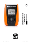
1
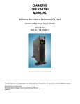
OWNER'S
OPERATING
MANUAL
SSG SeriesTM Rackmount Industrial-Grade UPS Plus®
Uninterruptible Power Supply Models:
SSG1.5KRM-1 - 1.5kVA, 1050W, 120Vac, -20ºC - 55ºC (-4ºF to 131ºF) Operation
SSG1.5KRM-2 - 1.5kVA, 1050W, 230Vac, -20ºC - 55ºC (-4ºF to 131ºF) Operation
SSG2.2KRM-1 2.2kVA, 1540W, 120Vac, -20ºC - 55ºC (-4ºF to 131ºF) Operation
SSG2.2KRM-HW 2.2kVA, 1540W, 120Vac, -20ºC - 40ºC (-4ºF to 104ºF) Operation
SSG2.2KRM-2 - 2.2kVA, 1540W, 230Vac, -20ºC - 55ºC (-4ºF to 131ºF) Operation
SSG3KRM-1 3kVA, 2100W, 120Vac, -20ºC - 55ºC (-4ºF to 131ºF) Operation
SSG3KRM-HW 3kVA, 2100W, 120Vac, -20ºC - 40ºC (-4ºF to 104ºF) Operation
SSG3KRM-2 - 3kVA, 2100W, 230Vac, -20ºC - 55ºC (-4ºF to 131ºF) Operation
SSG Rackmount Models
FALCON® Electric Inc., 5116 Azusa Canyon Rd., Irwindale, California 91706, 626.962.7770, Fax 626.962.7720, Email: [email protected]
2012 Falcon® Electric Inc. All rights reserved.
All other brand names and trademarks are the property of their respective owners.
The information stated in this document is subject to change without notice. 2012-24--1
Falcon®, Falcon® Electric and UPS Plus logos are registered trademarks of Falcon Electric, Inc.
TABLE OF CONTENTS
SSG UPS Features.
.
.
.
.
SSG Series Double-Conversion On-line UPS Block Diagram.
Important Safety Instructions
(READ FIRST)
.
.
.
.
.
.
.
3
3
4
Chapter 1. Introduction
Manual Overview. .
Brief SSG Overview..
Load Segment Control.
.
Remote Emergency Power Off
RS-232 & USB
.
.
Communications Expansion Slot.
.
.
.
.
.
.
.
.
.
.
.
.
.
.
.
.
.
.
5
5
5
5
5
5
.
.
.
.
.
.
.
.
.
.
.
.
.
.
6
6
6
6
6
6
9
9
9
.
.
.
.
.
.
.
.
9
10
10
12
13
13
14
15
Chapter 2. SSG UPS Circuit Descriptions
Input FIlter.
.
.
Power Factor Correction.
DC/DC converter. .
.
DC/AC inverter
.
.
Battery packs
.
.
Battery charger. .
.
Manual bypass function.
.
Automatic bypass function. .
Output fIlter
.
.
Chapter 3. Installation
Unpacking
.
.
Inspecting the equipment .
Rackmount UPS setup
.
Free standing tower installation with
LCD display repositioning .
Battery bank installation
.
Extended battery bank information
Battery bank installation procedure
.
.
.
.
.
.
.
.
.
.
.
.
.
.
.
.
.
.
.
.
.
optional
.
.
.
.
.
.
.
.
.
.
.
.
.
.
mounting feet.
.
.
.
.
.
.
.
.
Chapter 4. Displays & Controls
LCD & LED indicators & icons.
.
Function/Test button
.
Set/Alarm Silence button
.
.
How to display the UPS Parameters .
.
.
.
.
.
.
.
.
.
.
.
.
16
17
17
17
Chapter 5. UPS Operation
Operating Modes .
.
Normal On-line Mode
Battery Mode
.
Bypass Mode
.
How to turn on the UPS
.
How to DC start the UPS
.
How to turn off the UPS
.
.
.
.
.
.
.
.
.
.
.
.
.
.
.
.
.
.
.
.
.
.
18
18
18
19
19
19
19
.
.
.
.
.
.
.
.
.
.
.
.
20
20
21
22
.
.
.
.
.
24
25
25
26
27
.
.
.
.
.
.
Chapter 6. UPS Setup, Configuration & Programming
How to place the UPS into setup mode.
Setting the Green Mode.
.
.
Setting the UPS output voltage.
.
Setting the load segment options.
.
Chapter 7. Communications
RS-232 & USB
.
.
.
.
.
REPO
.
.
.
.
.
.
SSG1.5KRM-1 rear panel layout
.
.
.
SSG2.2KRM-1 & SSG3KRM-1 rear panel layout..
.
SSG2.2KRM-HW & SSG3KRM-HW rear panel layout & wiring.
Chapter 8. Maintenance
Storing the UPS .
.
.
When to replace batteries .
.
SSG1.5KRM-X Internal Battery Replacement
SSG2.2KRM-X, SSG3KRM-X, SSGR & SSGR-X
Performing a manual battery test
.
Recycling used battery packs
.
Chapter 9. Troubleshooting .
.
.
Chapter 10. Technical Support
.
.
Warranty
.
.
.
.
Specifications
.
.
.
.
2
.
.
.
.
.
.
.
.
.
Battery Replacement.
.
.
.
.
.
.
.
.
.
.
.
.
.
.
.
.
.
.
28
29
29
30
30
32
33
37
38
39-40
SSG SeriesTM Industrial-Grade UPS Features
True Double Conversion On-Line Sinewave Design
High Temperature 550 C Operation
LCD Display with Advanced Monitoring
Output Load Segment Control
Remote Emergency Power Off (REPO)
Input Power Factor Correction
Wide Input Voltage Window
Precision Output Voltage Regulation
Superior Brownout, Surge and Transient Protection
Optional Frequency Converter Operation
User Replaceable and Hot Swappable Battery Pack
Optional Extended Battery Banks & Chargers
RS-232C, USB & Optional SNMP/HTTP Communications
UPSILON UPS Monitoring & Management Software
RoHS Compliant
Two-Year Warranty
SSG Series Double-Conversion On-line UPS Block Diagram
3
IMPORTANT SAFETY INSTRUCTIONS,
SAVE THESE INSTRUCTIONS
RETAIN THIS USER MANUAL!
This manual contains important instructions which must be followed during the installation, operation
and maintenance of the SSG Series UPS, battery banks, options and batteries. Please read all
instructions before operating this equipment and save this manual for future reference.
All of the models presented herein are designed for installation and use in a temperature controlled
environment, free of contamination.
This UPS operates from utility power and contains a number of high current back-up
batteries; this information is important to all personnel involved. Please read this manual first
before continuing to unpack, install or operate this UPS.
STORAGE AND TRANSPORTATION
This UPS must be handled with care and given special attention due to the high amount of energy
stored within its internal sealed, lead acid batteries. Please retain the UPS shipping container in the
event the UPS needs to be returned for service. It has been designed to ship the UPS safely,
without shipping damage.
INSTALLATION
This UPS must be installed in a clean environment, free from moisture, flammable gases or fumes
and corrosive substances. Operate the UPS in an indoor environment with an ambient temperature
range specified by model number herein.
This UPS is designed for use with industrial, scientific or data processing class equipment.
DO NOT USE TO POWER LIFE SUPPORT EQUIPMENT, OR OTHER DESIGNATED
“LIFE CRITICAL” APPLICATIONS.
The maximum UPS output load (in watts) must never exceed that shown on the UPS rating
label. NEVER CONNECT equipment that could overload the UPS or demand half-wave
rectification from the UPS, for example: electric drills, vacuum cleaners or hair dryers.
Storing magnetic media on top of the UPS may result in data loss or corruption.
WARNING
This UPS should be installed according to the instructions in this manual. Failure to do so could
result in unsafe operation and could invalidate your warranty.
WARNING
Once batteries have reached the end of their life, ensure they are disposed of properly.
PLEASE REFER TO YOUR LOCAL LAWS AND REGULATIONS FOR BATTERY RECYCLING
REQUIREMENTS. NEVER DISPOSE OF BATTERIES IN A LAND FILL.
Do not dispose of battery pack or batteries in a fire. The battery may explode. Do not open
or mutilate the battery pack. Released electrolyte is harmful to skin and eyes. It may be toxic.
CAUTION
A battery can present a risk of electrical shock and high short circuit current. The following
precautions should be observed when working on batteries:
*
*
Remove watches, rings, and other metal objects.
Use tools with insulated handles.
4
1.0 INTRODUCTION
Manual Overview
This user manual has been written to provide basic information about the Falcon SSG Series
Industrial Grade UPS Plus. SSG models are available in nominal power ratings of 1500, 2200 and
3000 VA . The SSG Series is a compact, rugged, double conversion, "on-line" UPS. It provides
continuous power conditioning and accepts a wide range input voltage while providing tight output
voltage regulation with a true sinewave output. The SSG Series UPS protects your sensitive
electronics equipment against the widest range of power problems, including power failures, power
sags, power surges, brownouts, line noise, high voltage spikes, frequency variations, switching
transients, and harmonic distortion.
This manual also describes unpacking, unit installation, the major features of the SSG Series UPS,
as well as detailed operation, configuration and troubleshooting.
The specifications section states all of the detailed parameters of operation for the SSG Series, and
provides general information on approvals and certifications.
Brief SSG Overview
The Falcon SSG Series Industrial-Grade UPS may be positioned vertical for desktop or floor
standing applications. Brackets are supplied to accommodate installation into a standard 19 inch
equipment rack.
The SSG Series front panel features a graphical LCD display, providing detailed operational information at a glance. The display enables the user or field service engineer to easily monitor and troubleshoot localized power problems, in addition to UPS operation. UPS control and programming is
easily accomplished using the Standby, Function/Test and Set/Alarm Silence buttons. Two levels of
audible alarms are also provided when the unit is operating on battery.
The SSG Series rear panel supports the following:
a. Load Segment Control - Multiple output receptacles are grouped into one continuous and two
programmable load segments. The two programmable load segments may be set to “shed” or turn
off the load segment at loss of utility voltage or when the low battery level has been reached. This
allows non-essential loads to be turned off, extending the amount of battery runtime.
b. Remote Emergency Power Off (REPO) - SSG models are equipped with a REPO connector that
may be interfaced with a computer room’s isolated, normally closed REPO and meets NFPA 70,
NEC645-11.
c. RS-232 and USB Ports - These ports may be used to provide communications between the UPS
and a network server or other computer systems. When used in conjunction with the supplied
UPSILON software, they give the ability to remotely monitor and control the UPS. The software will
automatically save all open computer files and initiate an unattended shutdown in the event of a loss
of utility. It supports most MS Windows and Linux operating systems. An optional Unix version is
available through Falcon at an additional cost.
d. Communications Option Board Expansion Slot - The slot supports the installation of an
optional SNMP/HTTP Agent board or contact closure interface board. The SNMP/HTTP Agent board
is a TCP-IP addressable solution to remote UPS monitoring and management via LAN, WAN or the
Internet. The agent board is supplied with client software that will remotely shutdown multiple servers
or computers through the Ethernet LAN. A CD containing software clients and a SNMP MIB II
compliant MIB is provided that supports most popular operations systems.
5
2.0 SSG UPS CIRCUIT DESCRIPTIONS
Input Filter
This portion of the circuit provides surge protection, certified to meet IEC 61000-4-5 and IEC 801-5.
It also filters out both electro-magnetic interference (EMI) and radio frequency interference (RFI) and
prevents excessive levels from being conducted back to the utility source. All SSG Series rackmount
models have been tested and comply with FCC Class B requirements.
Input Power Factor Correction
While the UPS is operating from the utility source, this circuit converts utility AC power to regulated
DC power for inverter use. It corrects the input current to maintain a sine waveform to minimize the
amount of current distortion that will be reflected back to the utility.
DC/DC Converter
The DC/DC converter utilizes energy from batteries and boosts up the DC bus voltage to a level
required by the inverter. This allows the inverter to operate continuously at optimum efficiency and
voltage. The converter incorporates a patented circuit which reduces the amount of ripple current
and EMI interference to the battery, increasing the overall battery life.
DC/AC Inverter
In utility mode operation, the inverter utilizes the regulated DC output to invert DC back into clean,
regulated sinewave AC power. When utility power fails, the inverter will receive its energy from the
battery through the DC/DC converter. In both modes of operation, the UPS inverter is on-line and
continuously generating clean, regulated AC output power to the load. The IGBT, PWM inverter is of
a very robust design and produces a pure sinewave output with a +/-2% voltage regulation. Having a
very low output impedance, it can supply the high current demands of high inrush and non-linear
loads.
Battery Packs
The SSG Series UPS utilizes a flame retardant battery pack comprised of four 12V, 7AH,
valve-regulated, sealed lead acid (VRLA) batteries in each pack. All SSG battery packs are
interchangeable between SSG 1.5kVA-3kVA models. They are easily replaced through the UPS front
panel. See replacement instructions outlined in this manual.
To maintain the optimum battery life, the user should operate the UPS in an ambient temperature of
68ºF to 77ºF (20ºC to 25ºC). Some SSG Series UPS models have batteries that may be rated operational at -20º C - 55º C (-4º F to 131º F), at these temperatures, battery life will be substantially
reduced. Optional extended battery modules are available through Falcon and will extend the
amount of battery runtime. Please refer to the exact UPS model in the attached specificaitons for the
specific battery option part number.
Battery Charger
The battery charger utilizes energy from the utility power to continuously charge the UPS batteries.
The charger operates in "constant power" mode. The UPS batteries are being charged whenever the
UPS is plugged in, turned on and operating from utility power. The internal UPS battery charger
output is rated at 1 amp.
CAUTION: When making battery bank connections to the UPS, alwasy verify the battery bank
circuit breaker(s) are in the off position. PRIOR to turning on the first battery bank circuit
breaker, ALWAYS DEPRESS AND HOLD THE BATTERY PRECHARGE PUSHBUTTON LOCATED
ON THE UPS REAR PANEL WHILE TURNING ON THE FIRST BATTERY BANK CIRCUIT BREAKER TO PREVENT UPS DAMAGE.
6
Lithium-Ion Batteries
SSG1.5KRM-1-LI and SSG1.5KRM-2-Li models are equipped with optional internal Lithium-IonPhospate Batteries. In comparison with VRLA (valve regulated sealed lead-acid) batteries which
weigh 6 lbs. each, the Lithium-ion batteries weigh 1.8 lbs each while supplying almost twice the
battery runtime as the same model equipped with VRLA batteries.
CAUTION: If not handeled or disposed of properly Lithium-Ion batteries are extremely dangerious. Lithium-Ion-Phosphate batteries must be recycled - never dispose of the batteries in a
land-fill or trash.
Caution: Should a model SSG1.5KRM-1-LI or SSG1.5KRM-2-LI UPS require shipment by air
transporation the shipping instrucitons on the following page must be followed:
IMPORTANT SHIPPING INSTRUCTIONS
To ship by air you need to:
1)
Shipper must declare Hazardous materials/dangerous Goods description and proper shipping
name – Lithium batteries, contained in equipment.
2)
Identification Number – 3481(international)/3091(USA) note: that 3481 will be recognized in
the USA but the CFR still has 3091 since the US has not harmonized with the rest of the
world at this time.
3)
The 12V7 batteries have been tested to UN Manual of Tests and Criteria, Part III,
subsection 38.3.
4)
The 12V7 batteries are under 100Wh and are excepted from the regulations.
5)
The UPS must be packed in strong outer packaging constructed of suitable material of
adequate strength and design in relation to the packaging’s capacity and its intended use.
SAVE THE ORIGINAL SHIPPING CARTON, INSERTS AND PACKING MATERIALS.
6)
Each consignment with packages bearing the lithium battery handling label must be
accompanied with a document with an indication that:
•
the package contains lithium ion cells or batteries;
•
the package must be handled with care and that a flammability hazard exists if the
package is damaged;
•
special procedures must be followed in the event the package is damaged, to
include inspection and repacking if necessary; and
•
a telephone number for additional information.
11)
A Shipper’s Declaration for Dangerous Goods is not required.
12)
The words “Lithium ion batteries”, “not restricted” and “PI 967” must be included on the
air waybill, when an air waybill is used. The information should be shown in the “Nature and
Quantity of Goods” box of the air waybill.
IMPORTANT LITHIUM-ION BATTERY SAFETY INSTRUCTIONS
1)
Always replace the external UPS battery fuse with one of the same type and rating.
2)
Always replace batteries with A123 12V7 manufacturer and type. Never attempt to replace
with VRLA batteries.
3)
Never dispose of the UPS or its internal batteries in a land fill. The UPS and batteries must be
recycled by a state registered recycler.
4)
For emergency information concerning A123 Model 12V7 Lithium-Ion-Phosphate batteries
call:
US & Canada
1-800-232-9300
International
+1-703627-3887
5)
Never store a UPS containing Lithium-Ion batteries in temperatures above 65oC.
6)
Never attempt to replace the internal battery fuses. Batteries Must Be Replaced if internal
Battery Fuse is blown.
7
7)
8)
Never Apply a Short Circuit Across The Batteries as Personnel Injury, Fire or Explosion May
Result.
DANGER ---- NEVER ATTEMPT TO CONNECT AN EXTENDED BATTERY BANK
CONTAINING VRLA LEAD-ACID BATTERIES TO A UPS CONTAINING INTERNAL
LITHIUM-ION-PHOSPHATE BATTERIES.
8
Manual Bypass Function
A manual bypass button is located on the SSG front panel. When the UPS is operating from utility in
the normal on-line state, depressing this button will cause the UPS to transfer to bypass. Depressing
the bypass button again will return the UPS to the normal on-line condition.
Automatic Bypass Transfers
The SSG Series UPS will automatically switch to bypass to energize the connected load when the
UPS is first turned on, encounters an overload, encounters an over temperature condition, or upon a
UPS failure condition. Should any of these events occur, the UPS will transfer to bypass mode,
sound an audible alarm and provide a "bypass" indication on the LCD display.
Output Filter
As with the input filter stage, the output filter maintains conducted (EMC) and RFI levels below FCC
Class B limits.
3. 0 INSTALLATION
Unpacking
The SSG Series UPS may be shipped in a number of boxes, depending on the model and
configuration ordered. The number of boxes you have received should be as indicated:
MODEL
BATTERY MODULE
SSG1.5KRM-X
SSG2.2KRM-X
SSG3KRM-X
NUMBER OF BOXES
n/a (internal battery pack)
1 battery module
1 battery module
1 box shipped
2 boxes shipped
2 boxes shipped
If you have not received the proper number of boxes, please contact Falcon Electric Customer
Service at 1-800-842-6940.
This UPS is shipped complete with all cables required for operation, including UPSILON software,
and rackmount ears for 19" rackmount shelf mounting. A full list of the box contents is provided as
follows:
SSG1.5KRM-X
Box 1 contains:
SSG2.2KRM-X / SSG3KRM-X
Box 1 contains:
UPS module with fitted battery pack
RS-232 cable
Software CD
Manual
19" rack ears (+ screws)
UPS module without battery
RS-232 cable
Software CD
Manual
19" rack ears (+ screws)
Box 2 contains:
Battery module
Battery connection cable
Keyhole hardware
19" rack ears (+ screws)
1 set of mounting plates & securing hardware
9
Inspecting The Equipment
Visually inspect the UPS for freight damage. If any equipment has been damaged during shipment,
keep the shipping cartons and packing materials for the carrier, and immediately file a claim for
“shipping damage” with the carrier. If you discover damage after acceptance, file a claim for
“concealed damage”.
To file a claim for shipping damage or concealed damage:
1.
YOU MUST file with the carrier within 15 days of receipt of the equipment;
2.
YOU MUST send a copy of the damage claim within 15 days to Falcon Electric, Inc.
CAUTION
The UPS and Battery Module are heavy. Take proper precautions when lifting or moving them.
1. Install the UPS indoors in a controlled environment.
2. Place the UPS in an area with unrestricted airflow around the unit, away from water, flammable
liquids, gases, corrosives, and conductive contaminant.
3. Maintain a minimum clearance of 4 inches in the front and rear of the UPS.
4. Maintain an ambient temperature range specified in the model specificaiton. To maximize the life
time of the batteries, an ambient temperature of 68ºF to 77ºF (20ºC to 25ºC) is recommended.
OPERATION IN TEMPERATURES ABOVE 77ºF (25ºC) WILL REDUCE BATTERY LIFE.
5. The SSG Series UPS can be installed in either a free-standing mini-tower or into a 19 inch
equipment rack. Follow the appropriate instructions in either Rackmount UPS Setup or
Free-standing UPS Installation.
Rackmount UPS Setup
All SSG Series models are shipped with front panel mounting ears that allow the unit to be installed
in a 19" equipment rack. Each UPS unit and external battery enclosure requires 2U (3.5 inches) of
vertical rack space.
NOTE !
The rack-mounting ears WILL NOT support the weight of the UPS or battery bank
by themselves. They are only to be used to secure the UPS to the front rails of the
rack. Mounting rails or an equipment shelf are required to support the weight of
each UPS or battery module.
Use the following procedure to install the UPS in an standard 19” equipment rack:
1.
Place the UPS on a flat, stable surface with the front of the UPS facing you.
2.
Align the mounting ears with screw holes on the side of the UPS and secure with the
supplied screws.
3.
If installing the Battery Module, repeat above STEPS.
4.
For slide rail installations, fasten the inner parts of the slide rails to the UPS on both
sides with the screws provided.
CAUTION: When making battery bank connections to the UPS, alwasy verify the battery bank
circuit breaker(s) are in the off position. PRIOR to turning on the first battery bank circuit
breaker, ALWAYS DEPRESS AND HOLD THE BATTERY PRECHARGE PUSHBUTTON LOCATED
ON THE UPS REAR PANEL WHILE TURNING ON THE FIRST BATTERY BANK CIRCUIT BREAKER TO PREVENT UPS DAMAGE
10
5.
6.
** Securing hardware, slide rails and rail extensions are sold separately. Contact
Falcon Electric for these additional options and any assistance needed.**
Attach the two mounting brackets to the rack's mounting rails. The brackets allow
adjustment of up to eight inches of the slide assembly mounting position, front-to-back,
on the rack-mounting rails. Determine which adjustment holes to use on the bracket,
and attach it to the slide assembly on the stationary outer slide.
11
7.
8.
9.
10.
11.
Install the slide assemblies, with brackets into the rack enclosure.
The return flanges on the mounting brackets and outer parts fit to the inside of the
rack-mounting rails.
Verify the slide assemblies are in the same alignment position on all four rack-mounting
rails. After checking alignment, TIGHTEN ALL SCREWS.
Insert the UPS, with inner parts attached, into the slide assemblies. You may need to
depress the locking mechanisms on the inner and outer parts of the slide assemblies
to allow the slides to retract. The UPS should move smoothly forward and backward on
the slide assemblies. If not, recheck alignment.
Once the UPS is installed in the rack, the load may be connected to the output of the
UPS. Ensure the equipment being connected is turned off. Plug all loads into the
output receptacles on the rear of the UPS. Plug the UPS into a dedicated wall
receptacle that is protected by a circuit breaker or fuse in accordance with national and
local electrical codes.
Use a 15 amp rated device for 1500 VA units, 20 amp for the 2200VA, and
30 amp for 3000VA. The wall receptacle must be grounded.
To turn on the UPS, switch on the input circuit breaker; wait for the UPS to switch from
bypass to inverter mode and then turn on the connected equipment.
Free-standing (tower) Installation (mounting feet to be purchased seperately)
When installing the SSG Series UPS in a free-standing configuration, mounting feet for the
SSG1.5KRM-1 model may be purchased seperately to stableize the UPS
provided with mounting feet (shown below, left) to stabilize the UPS. The SSG2.2KRM-1 and
SSG3KRM-1 models are provided with keyhole hardware to "lock" the UPS and battery bank units
together. This key lock is also required if additional battery packs are added.
X
Mounting feet for additional
battery banks
Mounting feet
SSG1.5KRM-X Free Standing
SSG2.2KRM-X & SSG3KRM-X Free Standing
12
LCD Display Repositioning
WARNING: Refer the repositioning of the LCD display to a qualified electronic technician or
the Falcon Service Department. LIVE COMPONENTS ARE INSIDE THIS UPS AND RISK OF ELECTRICAL SHOCK.
Prior to anyone starting to attempt the repositioning of the LCD display, SERVICE
PERSONNEL MUST FIRST disconnect the UPS line cord and power plug, remove
the battery fuse located on the UPS rear panel, disconnect any external battery
banks and let the UPS discharge for one hour.
The default LCD display mounting is for horizontal (Rackmount) viewing. To reorient the LCD display
for vertical (Free Standing) viewing, remove the left half of the front plastic bezel by unscrewing the
screws to the far left of the chassis. Next, remove the four screws securing the right plastic panel
and pull the right panel forward evenly. Refer to the following figure, unscrew the LCD board and
rotate it 90 degrees, to the correct position for viewing. Use care when handling the LCD display and
associated cabling. Mount the front covers back and reinstall the screws.
SSG & HW Battery Bank Installation
(SSG1.5KRM-X internal battery, SSG2.2KRM-X & SSG3KRM-X standard battery bank and all SSG
extended battery banks)
Note:
Additional battery banks can be connected to the UPS to provide additional battery run time.
There are two models of extended battery banks available for the SSG Series. Falcon model number
SSGR is a universal battery bank without an internal charger. It may be added to any SSG 1.5-3kVA
models. For 2.2-3kVA models, the addition of this type of extended battery bank will cause the stated recharge time to multiply by the number of battery banks added. The addition of more than three
SSGR battery banks is not recommended. Use the SSGR-1 model universal extended battery models instead, as it incorporates internal battery chargers to assure proper battery recharging and
greatly reduces the amount of battery recharge time.
13
SSG Extended Battery Bank Information
EXTENDED BATTERY BANK (EBM)
OPTIONS
UPS Model
SSG1.5KRM
-1 &HW
SSG1.5KRM
-2 & HW
SSG2.2KRM
-1 & HW
SSG2.2KRM
-2 & HW
SSG3KRM-1
& HW
SSG3KRM-2
& HW
Extended # Of Recharge
Battery Battery Time in
Bank
Banks
Hours
Model
(to 90%)
Number
(2)
SSGR
Weight
(lbs.)
1
18
40.5
3
30
1
6
2
35
81
5
56
2
7
3
56
121.5
7
87
4
64
162
9
5
80
202.5
43.5
87
-1 120Vac
2A
130.5
54Vdc
3A
(2
-2
Chargers
230Vac
@1A each
174
1.5A
3
7
118
4
8
11
148
5
8
217.5
243
13
184
6
8
261
48Vdc
SSGR-1
SSGR-2
7
150
283.5
15
221
7
8
304.5
1
12
40.5
2
24
1
7
43.5
2
18
81
3
42
2
7
3
25
121.5
SSGR
SSGR
Number BACKUP
EXTENDED BATTERY BANK (EBM) OPTIONS
of parallel TIME (1)
(With Internal Battery Charger)
UPS
BATTERY
battery
Extended # Of Recharge Charger Charger Recharge Weight
Battery strings (Models
BANK
Battery Battery Time in
Input
Output Current
(lbs.)
Bus
DIMENSIONS
With &
Bank
Banks Hours
Voltage & Voltage
Voltage
(Inches)
Without
Model
(to 90%) Current
Charger
Number
4
63
96Vdc
SSGR-1
SSGR-2
3
8
4
8
87
-1 120Vac
2A
130.5
3A
109Vdc
(2
(2 x
-2
Chargers
230Vac 54Vdc) @1A each
174
1.5A
4
35
162
5
83
5
46
202.5
6
104
5
8
217.5
6
56
243
7
125
6
8
261
7
68
283.5
8
146
7
8
304.5
1
12
40.5
2
14
1
6
43.5
2
18
81
3
27
2
7
3
25
121.5
4
41
8
4
35
162
5
56
4
9
5
35
202.5
6
71
5
8
217.5
6
56
243
7
87
6
8
261
7
68
283.5
8
103
7
8
304.5
SSGR-1
SSGR-2
3.5 x 16.8 x
21.5
(each battery
bank)
87
-1 120Vac
2A
130.5
109Vdc
3A
(2
(2 x
-2
Chargers
230Vac 54Vdc) @1A each
174
1.5A
3
96Vdc
3.5 x 16.8 x
21.5
(each battery
bank)
3.5 x 16.8 x
21.5
(each battery
bank
1. BATTERY TIMES ARE IN MINUTES @ FULL LOAD AND INCLUDE UNITS INTERNAL BATTERIES ON 1KVA UNIT. (TIMES ARE APPROXIMATE AND SUBJECT TO TEMPERATURE,
CONDITION AND TYPE OF LOAD).
2. RECHARGE TIME WITH INTERNAL UPS CHARGER ONLY
14
Battery Bank Installation Procedure
The battery modules have been designed to be placed on one side of the UPS as shown below.
1.
2.
3.
4.
Visually inspect the battery module for any freight damage. Report damage to the
carrier and Falcon Electric immediately.
Use the mounting feet to secure the unit and to prevent them from tipping over. One
additional set of mounting feet base extensions ships with each battery bank.
Turn off the battery disconnect switch and connect the supplied battery bank cable to
the UPS connector located on the rear of the battery bank. Next connect the other end
of the cable to the battery bank connector located on the rear of the UPS as shown.
Turn on the battery disconnect switches located on the back on the rear of the
battery bank(s).
15
4.0 DISPLAY & CONTROLS
The diagram below shows the basic functions of the front panel for all SSG Series 1.5-3kVA UPS
models.
Indicators and Icons located on the LCD models LED display:
Green Mode: The bulb icon is displayed continuously when the Green Mode function is
enabled. It will be flashing when the UPS has switched to Green Mode due to the UPS
output load decreasing to less than 3% of the total UPS output rating. The UPS is shipped
with the Green Mode disabled. See Green Mode setting instructions.
Audible Alarm: The speaker icon will be displayed during an alarm condition. It will
be flashing when the audible alarm has been silenced.
UPS Fault Condition: This icon will be displayed when an alarm condition exists. Refer to
page 29 of this manual and attempt to correct the alarm condition.
Test: The Test icon will be displayed and flash whenever the UPS is conducting a
Self/Battery Test. Not on LED models.
Output Load %: The greater the load, up to three vertical bars will be illuminated at the
ends of the icon. Each bar represents 25% of the UPS output rating.
Inverter Status: This icon will be displayed when the UPS is in Inverter mode.
PFC Status: This icon will be displayed with PFC is functioning.
Utility Power Status: The Line Cord icon will be displayed when utility power is
present.
Charger Status: When the battery charger is operating, the gas pump icon will be
displayed.
Battery Mode: When the UPS is in battery mode this icon will be displayed.
Battery Level: The battery icon or LED indicates the battery capacity. The more battery
capacity available, the more bars that will be illuminated. Each bar represents 25%.
Fan in high speed mode: The HS Fan icon is displayed when the UPS cooling fan
is in high speed mode, typically during battery mode operation.
Fan in medium speed mode: The MS Fan icon is displayed when the UPS cooling fan is
in medium speed mode, typically when utility is present.
Fan in low speed mode: The LS Fan icon is displayed when the UPS cooling fan is
in low speed mode, typically when the UPS is in bypass.
16
Controls (all models):
The primary front panel user controls consist of one input circuit breaker and three push-buttons:
The switch located to the right of display is the main input circuit breaker and controls the connection
of utility power to the UPS and its internal battery charger.
.
The three buttons located to the left of the LCD display are for primary manual control and programming of the UPS. From top to bottom they are designated "Function/TEST", "Set/Alarm Silence", and
"Bypass".
Function/Test Button
This button has two functions:
1
Initiates internal UPS Setup mode to allow for configuration changes. Setup mode is initiated
by pressing both the "Function/Test" and Set/Alarm buttons down and holding them for one
second.
2
Manual Battery Test - If depressed for less than three seconds, it initiates an immediate
battery test.
Manual Battery Test Description - When the UPS is operating normally from utility power, pressing
the test button will cause the UPS to test the voltage status of the batteries for 10 seconds. During
that period, the battery, if first determined to be good, will supply power to the UPS. Should defective
batteries be detected, the audible alarm will sound one long tone, and the UPS will continue to
operate from the utility voltage, without going to battery mode. During the battery test, the output of
the UPS will not be adversely affected.
Set/Alarm Silence Button
This button has three functions:
1
Disables the audible alarm buzzer
2
Scrolls the display through the various UPS parameters.
3
Sets configuration changes (when pressed in setup mode only).
Disable the Audible Alarm - Pressing the button for one second will turn off the audible alarm. This
will cause future notification of minor alarms to be silenced.
NOTE!
THE FOLLOWING ALARMS CANNOT BE SILENCED:
OVER TEMPERATURE, PFC OVER CURRENT, INVERTER OUTPUT OVER LOAD,
LOW BATTERY AND UPS OR CHARGER FAILURE.
How to Display The UPS Parameters - Repeat pressing of the Set/Alarm button will cause UPS
input and output parameters to be displayed on the lower portion LCD display in the following order.
The input voltage, output voltage, output frequency, battery voltage, percentage of output load, input
current, internal UPS temperature and the output current.
17
CAUTION
When the UPS is in Normal On-line mode, pressing the bypass button once will put the UPS
into Bypass Mode. While in bypass, should the utility power become unavailable, the UPS
output will turn off and the UPS will shut down.
Once the unit is in Bypass Mode operation, pressing this button again will force UPS back to
on-line mode operation.
5.0 UPS OPERATION
OPERATING MODES (LCD models only, LED models are self-explanatory)
The following outlines the UPS status for each mode of operation as displayed by the LCD.
NORMAL ON-LINE MODE OPERATION
During normal on-line operation, utility power provides energy to the UPS. The filters, power factor
corrector and the inverter process the power to provide computer grade power to connected loads.
The UPS maintains the batteries in a fully charged state.
The LCD display icon configuration on the left indicates on-line mode
operation, indicating the percent of load, inverter, PFC, line, charger
and battery operation and status. The fan is shown at medium
speed.
The dark, solid line on the MIMIC portion of the display indicates the
normal mode power flow from input, through the inverter, to load and
from the input, to the charger and into the battery.
BATTERY MODE OPERATION
The battery mode icon configuration is displayed during a loss of utility power or during excessively
high line voltage conditions. When in battery mode, the UPS battery supplies energy to the DC to
DC converter, and then on to the inverter, which powers the connected load. During the battery
discharging, the audible alarm will beep. The rate of the beeping will increase as the battery runs low
(low battery), prior to UPS shut down. Once the low battery warning is sounded, there will be about
one minute of battery runtime remaining.
After the UPS has shut down, when utility power has been restored, the UPS will automatically
restart. For approximate battery run times, refer to the specifications and extended battery runtime
chart in this manual. The runtime is based on a resistive load being connected to the UPS
output, and an ambient temperature of 77ºF (25ºC).
The LCD display icon configuration on the left indicates the UPS is
in Battery Mode. The dark solid line indicates battery power flow to
the DC to DC converter and on to the inverter. The fan is shown in
high speed mode. The bars inside the battery icon indicate the
amount of battery capacity remaining; each bar represents a 25%
capacity increment. As capacity decreases, fewer bars will remain
illuminated. The charger icon is turned off.
18
BYPASS MODE OPERATION
The UPS will automatically transfer to Bypass Mode in the event it is overloaded, experiences an
internal failure and for the conditions listed below. When in bypass, the UPS will transfer the connected load directly to the incoming utility power. When in bypass mode, Battery Mode will not be
available. However, the utility power will continue to be passively filtered by the UPS. Additionally,
the UPS will sound an audible alarm and switch to Bypass Mode automatically upon the following
conditions:
* The UPS has experienced an over temperature condition.
* The UPS has experienced an overload condition of 101 to 110% for over 120 seconds.
* The UPS has experienced an overload condition of 111 to 150% for over 20 seconds.
* The UPS has experienced an overload condition of over 150%.
* The UPS detects a fault in the battery or UPS electronics.
The LCD display icon configuration on the left indicates the UPS is in
Bypass Mode. The dark solid line shows the input connected directly to
the connected load. Another dark solid line shows the input power to
the battery charger icon, then to the battery. The Fan is shown in low
speed mode.
GREEN MODE OPERATION
When Green Mode is turned on using the UPS programming interface, the SSG unit will automatically switch to "Green Mode" (Bypass Mode), once the connected load drops to less than 3% of the
UPS’s rated output. The load will operate directly from utility power, similar to Bypass Mode. The
LCD display will indicate the UPS is in Bypass Mode, the Green Mode bulb icon will be flashing. If
the load is increased to over 3% of the UPS output rating, the UPS will automatically switch back to
normal on-line operation. All SSG models are shipped from the factory with Green Mode turned off.
To enable Green Mode, refer to the section on UPS Setup, Configuration & Programming. See the
green mode configuration section for further details and cautions.
How to Turn On the UPS (with utility power)
Once installation has been complete, the UPS can be powered up. With utility power present, turn
on the UPS input circuit breaker located on the front panel. The UPS will enter an Auto-Test state
and all of the LCD indicators will be illuminated flashing for ten seconds and then return to a
normal state. The UPS will start up in bypass mode and after several seconds, should transfer to the
normal on-line mode.
How to DC Start the UPS (without utility power)
In the event utility power is not available, the UPS may be started up in battery mode. To turn on the
UPS without utility power available, press and hold the "BYPASS" button. The UPS will start on
battery and supply power to the connected loads until the batteries are depleted. Always recharge
the batteries immediately by connecting the UPS to utility power and turning on the UPS input circuit
breaker after any full battery discharge. For DC start operation the load segment control must be set
to Continuous Mode operation.
How to Turn Off the UPS
To turn off the UPS:
While in normal on-line mode, press the Bypass button for one second. The UPS will go into Bypass
Mode. Next, turn off the input circuit breaker. The unit will shut down after about 30 seconds.
While in battery mode: Press the Bypass button for one second. The unit will shut down after about
30 seconds.
19
NOTE!
DURING SHUT DOWN, DO NOT PRESS ANY BUTTON SINCE UPS MIGHT BE
RE-ENERGIZED AND DELIVER POWER TO ITS OUTPUT UNEXPECTEDLY.
6.0 UPS SETUP, CONFIGURATION & PROGRAMMING
The following section describes how to reconfigure the internal UPS setup options, by using the
Setup, Configuration & Programming Mode. The setup options include: The UPS output voltage,
enabling or disabling Green Mode and output Segment Control operational mode settings.
CAUTION
Never change the voltage settings when the UPS is ON and powering any connected
loads.
How To Place the UPS Into Setup/Configuration Mode
To place the UPS into configuration mode: press the "Function/Test" and "Set/Alarm Silence" buttons
at same time and hold them for one second. The unit will emit one audible beep and display function
and status bit window at the bottom of the LCD display, entering Configuration Mode.
Note on the bottom of the display panel, you will see a single row, 8 BIT
column located at the bottom of the display. The right most bit is function
BIT 0, with the remaining seven bits to the left, function bits 1 through
6. The last BIT 7 is the Status Bit and will indicate the setting status of the
other Function bits. Repeat pressing of the "Function/Test" button will move
the dot from function BIT 0 (far right) to function BIT 6. When selecting
function BIT 0 through BIT 6, observe whether status BIT 7 has a (Dot) or
(No Dot) displayed for the function bit selected. To select a dot or no dot
for the function you are presently in, press the "Set/Alarm Silence" button to
turn on (Dot) or turn off (No Dot) in status BIT 7. Next, press the
“Set/Alarm Silence" and “Function/Test" buttons at same time, and hold for
one second. The audible alarm will sound one short beep to acknowledge
the UPS has stored the selected settings.
Setting the Green Mode Function (set to disabled from factory)
Green Mode is a power saving feature that should only be used in non-critical applications when the
connected computer or equipment is the only device being protected by the UPS and when turned
off, UPS battery backup is no longer necessary. When the Green Mode is enabled and the connected load decreases to less than 3% of the full rated UPS output capacity, the UPS will automatically
switch from on-line to Bypass Mode, 30 seconds after the drop in load has been detected. After the
UPS has switched to Bypass Mode, the Green Mode bulb icon will flash to indicate the UPS is in the
energy saving Green Mode. While in Green Mode, should the load increase to greater than 3% of
the UPS's full output rating, the UPS will automatically return to normal On-line Mode operation.
CAUTION- When Green Mode is enabled, and the UPS has switched to Bypass Mode due to a
reduction in load, THE UPS WILL NOT GO TO BATTERY MODE IN THE EVENT OF A UTILITY
FAILURE. THE CONNECTED LOAD WILL BE TURNED OFF. Turning Green Mode off in
configuration mode will restore normal UPS operation.
20
Green Mode Setup
How to Enable or Disable Green Mode (Function Bit 2)
To Enable:
1. Press the "Function/Test" and “Set/Alarm Silence" buttons at same time and
hold them for one second. The unit will sound one beep and then enter the
Configuration Mode.
2. Press the "Function/Test" button two times to move the dot from function BIT 0
to function BIT 2 (The Green Mode function).
3. Press the "Set/Alarm Silence" button to enable (NO DOT) BIT 7. (The reverse of
other feature enable settings)
4. Press the "Set/Alarm Silence" and "Function/Test" buttons at same time again
and hold for one second. The alarm will sound one short beep to acknowledge
the UPS has stored the setting.
To Disable: (Factory Default)
1. Press the "Function/Test" and "Set/Alarm Silence" buttons at same time and
hold them for one second. The unit will sound one beep and then enter the
Configuration Mode.
2. Press the "Function/Test" button two times to move the dot from function BIT 0
to function BIT 2 (Green Mode function).
3. Press the "Set/Alarm Silence" button to turn off (DOT) BIT 7. (The reverse of other
feature disable settings)
4. Press the "Set/Alarm Silence" and "Function/Test" buttons at same time again
and hold for one second. The alarm buzzer will sound one short beep to acknowledge
the UPS has stored the setting.
How to Set the UPS Output Voltage (Function Bits 0 & 1)
The SSG Series UPS is shipped configured from the factory with its output voltage set to 120Vac.
For most North American applications, the UPS output voltage will not have to be changed.
CAUTION: NEVER CHANGE THE UPS OUTPUT VOLTAGE WHILE IT HAS EQUIPMENT
CONNECTED TO ITS OUTPUT RECEPTACLES.
Make output voltage configuration changes and verify the desired output voltage is present at the
UPS output using the UPS output voltage display function. Next, verify that all of the equipment to be
connected to the UPS will operate satisfactorily on the newly selected output voltage.
CAUTION:
When the UPS output voltage is set to 100Vac, the maximum amount of load that
can be connected to the UPS must be derated (reduced) by 15%.
Output
Voltage
Function BIT(s)
Status Bit (BIT 7)
120Vac
115Vac
110Vac
100Vac
BIT 0
BIT 0
BIT 0
BIT 0
For
Fro
For
For
&
&
&
&
BIT 1
BIT 1
BIT 1
BIT 1
BIT 0,
BIT 0,
BIT 0,
BIT 0,
set
set
set
set
bit 7 On (Dot), For BIT 1, set bit 7 On (Dot) (default)
bit 7 Off (No Dot), For BIT 1, set bit 7 On (Dot)
bit 7 On (Dot), For BIT 1, set bit 7 Off (No Dot)
bit 7 Off (No Dot), For BIT 1, set bit 7 Off (No Dot)
21
Output Voltage Select Setup
Example - How to Set the UPS Output Voltage to 115Vac (-1 models) or 230Vac (-2 Models)
1. Press the "Function/Test" and "Set/Alarm Silence" buttons at same time and hold
them for one second. The unit will emit one alarm beep and then enter the
Configuration Mode.
2. Press the "Function/Test" button eight times to move the dot to function BIT 0.
3. Press the "Set/Alarm Silence" button turn off (no dot) Status BIT 7.
4. Press the "Function/Test" button one time and move the dot to function BIT 1.
5. Press the "Set/Alarm Silence" button to turn on (dot) Status BIT 7.
6. Press the "Set/Alarm Silence" and "Function/Test" buttons at same time again
and hold for one second. The alarm buzzer will sound one short beep to acknowledge the
UPS has stored the settings.
7. You must now restart the UPS before the new voltage setting will be in effect.
How to Set the UPS Load Segment Control Options (Function Bits 3, 4, 5 & 6)
Three conditions of automatic load segment control may be programmed for two separate output
load segments. Additionally, one continuous load segment is provided. Per the model-specific rear
panel pictures that follow, the two programmable and one continuous load segments are assigned to
specific output receptacles located on the UPS rear panel.
For each programmable load segment, the following conditional states may be selected:
1. Turn off the assigned load segment when utility power is lost (bits 3 & 5)
2. Turn off the assigned load segment whenever low battery is reached (bits 4 & 6).
3. Load segment bits are turned off making the load segment continuous.
Load Segment Control Setup
22
Making Load Segment Settings
A. Setting load segments to automatically turn off the load segment when utility power is lost
1. Press the "Function/Test" and "Set/Alarm Silence" buttons at same time and hold
them for one second. The unit will emit one alarm beep and then enter the
Configuration Mode.
2. Press the "Function/Test" button repeatedly and move the dot to function BIT 3 (for
load segment 1), or BIT 5 (for load segment 2).
3. Press the "Set/Alarm Silence" button once to turn on (dot) Status BIT 7.
4. Press the "Set/Alarm Silence" and "Function/Test" buttons at same time again
and hold for one second. The alarm buzzer will sound one short beep to acknowledge the
UPS has stored the settings.
B. Setting load segments to automatically turn off the load segment at low battery
1. Press the "Function/Test" and "Set/Alarm Silence" buttons at same time and hold
them for one second. The unit will emit one alarm beep and then enter the
Configuration Mode.
2. Press the "Function/Test" button repeatedly and move the dot to function BIT 4 (for
load segment 1), or BIT 6 (for load segment 2).
3. Press the "Set/Alarm Silence" button once to turn on (dot) Status BIT 7.
4. Press the "Set/Alarm Silence" and "Function/Test" buttons at same time again
and hold for one second. The alarm buzzer will sound one short beep to acknowledge the
UPS has stored the settings.
C. Setting load segments for continuous mode operation
1. Press the "Function/Test" and "Set/Alarm Silence" buttons at same time and hold
them for one second. The unit will emit one alarm beep and then enter the
Configuration Mode.
2. Press the "Function/Test" button repeatedly and move the dot to function BIT 3 (for
load segment 1), or BIT 5 (for load segment 2).
3. Press the "Set/Alarm Silence" button once to turn off (no dot) Status BIT 7.
4. Press the "Function/Test" button repeatedly and move the dot to function BIT 4 (for
load segment 1), or BIT 6 (for load segment 2).
5. Press the "Set/Alarm Silence" button once to turn off (no dot) Status BIT 7.
6. Press the "Set/Alarm Silence" and "Function/Test" buttons at same time again
and hold for one second. The alarm buzzer will sound one short beep to acknowledge the
UPS has stored the settings.
23
7.0 COMMUNICATIONS
All SSG Series UPSs are provided with the following communication ports:
*
RS-232 port with standard DB-9F serial port connector.
*
USB port supporting the connection of a standard USB interface cable.
*
One advanced communications option slot is provided on the rear panel of the UPS.
Unless an advanced communications option board has been previously purchased and
installed, the port will be covered with a small cover plate. This plate will be secured
with screws.
CAUTION:
NEVER INSTALL OPTION CARDS THAT HAVE NOT BEEN SUPPLIED BY
FALCON ELECTRIC OR ARE FOR ANOTHER FALCON MODEL WITHOUT CONSULTING WITH FALCON SERVICE.
Advanced communications option cards available from Falcon are:
Internal SNMP/HTTP Agent Board
Standard Dry Contact Interface Board
Note: A special external SNMP/HTTP Agent device is available that may be connected to the UPS's
RS-232 port. This allows for one dry contact interface board to be installed into the
Advanced Communications Option Slot concurrently.
CAUTION:
When an internal SNMP/HTTP AGENT device is installed into the Advanced
Communications Option Slot, the RS-232 port and UPSilon software may
not be used. The USB port may be used in conjunction with UPSilon software concurrently with the SNMP/HTTP agent.
RS-232 & USB Ports
This UPS is equipped with (1) RS-232 and (1) USB port located on the UPS rear panel. A standard
RS-232C interface cable is provided to allow for the connection of the UPS to another RS-232 port
found on most computers. The USB port interfaces with a standard USB cable to be supplied by the
end-user. The USB cable required is a - 4 Pin USB Type A (M) connector - 4 PIN USB Type B (M)
connector. The USB and RS-232 ports cannot be used concurrently. When an RS-232 or USB cable
has been connected, and the supplied UPSilon Computer Shutdown and Management software has
been properly installed on the connected computer, a high level of UPS management and
protection against lost or corrupted files is in effect. Please follow the installation and setup
instructions supplied on the UPSilon software CD.
The UPSilon users manual is also located on the UPSilon CD supplied with this unit. UPSilon
supports most popular operating systems. Should you have special UNIX requirements, please
contact Falcon Sales for information and pricing of UPSilon for UNIX.
24
The supplied Falcon RS-232 interface cable pin designations are as follows:
The computer RS-232 Port settings should be set to the following:
Remote Emergency Power Off (REPO)
A two-pin REPO connector is located on the rear panel of the UPS. The connector is shipped with a
jumper wire installed, to facilitate the normal operation of the UPS in the event an REPO
connection is not used.
The REPO function provides an interface for a NFPA 70, NEC 645-11 compliant Remote
Emergency Power Off (REPO) switch. The switch must have a normally-closed contact state that
opens when the REPO button is depressed (REPO ACTIVE).
When the REPO switch contacts are opened, which also turns the equipment room power and UPS
power off, the UPS output will immediately turn off all connected loads and then will shut down within
one minute. When the REPO switch contacts are closed, restoring the equipment room’s power, the
UPS will restart.
25
SSG2.2KRM-1 & SSG3KRM-1 Rear Panel Layout
Contact Closure Interface Card Option (New UA88374-SSG)
Replaces UA88374
Note: This card installs into the Communicaitons Option Slot
JUMPER SETTINGS
J1 through J7 = 1-2 DB-9 configured for Green cable (Default)
J1 through J7 = 2-3 DB-9 configured for standard RS-232 cable
Note: J1-J7 must be all configured 1-2 or 2-3, or UPS and PC may be damaged.
J9 Summery Alarm - 1-2 Normally Closed (Default), 2-3 Normally Open
J10 Low Battery = 1-2 Normally Closed, 2-3 Normally Open (Default)
J12 Model Selection = 1-2 XG & SSG Models, 2-3 IG & SVR-Pro-2 Models
J13 On-Bypass = 1-2 Disable, 2-3 Enable (Default)
26
DB-9 PIN ASSIGNMENTS
1
2
3
4
5
6
7
8
9
= Not Used
= Utility Loss, Normally Open
= Utility Loss, Normally Closed
= Common (tied to pin 7)
= Low Battery
= Remote Shutdown (5-12Vdc)
= Common (tied to pin 4)
= Alarm / Bypass
= Not Used
SSG2.2KRM-HW & SSG3KRM-HW Rear Panel Layout
OUTPUT WIRING DETAILS
LS1
Line
GND
LS1
Neutral
LS2
Line
27
LS2
Neutral
8.0 MAINTENANCE
All SSG Series UPS requires very little maintenance. The batteries are located inside user replaceable packs containing (4) CSB XTV1272 or equivalent, sealed, VRLA, maintenance-free,lead-acid
batteries.
Batteries must be kept recharged to prevent excessive self-discharging, which may result in their
premature failure. The UPS will continuously recharge the batteries when plugged in and
turned on.
1. The UPS and Battery Care
Keep the area around the UPS clean and dust free. If the area around the UPS becomes very dusty,
clean the area and the UPS with a vacuum cleaner. To assure the full 3-5 year battery life, keep the
UPS at an ambient temperature of 25ºC (77ºF).
2. Storing the UPS and Batteries
When storing the UPS for any length of time, it is recommended to plug and turn on the UPS for at
least 24 hours, every four to six months to ensure full recharging of the batteries. This will prevent
excessive battery self-discharge.
3. When to Replace Batteries
We suggest the battery pack(s) containing 10-12 year batteries, have the batteries replaced every 810 years for SSG units that are operated and maintained in a 25ºC environment. Higher temperature
operating environments will decrease the battery life. For 10-12 year batteries installed in a 50ºC
enviroments, they will need to be replaced about every four years.
In order to assure the performance of the SSG Series UPS, check the battery every two to three
months by pressing "Function/Test" button and conducting a battery test. If the UPS goes back to
normal On-line Mode in less than 10 seconds with one long beep, the batteries need replacing.
Contact Falcon Electric Service Department to order replacement battery packs.
4. Battery Pack Replacement
With the hot-swappable battery pack feature, the SSG Series UPS battery pack is easily replaced,
without having to turn the UPS off or disconnecting the load. Refer to the battery replacement section of this manual for replacement instructions.
NOTE!
NEVER ATTEMPT TO DISCONNECT THE BATTERIES OR REMOVE THE BATTERY FUSE OR TURN OFF THE BATTERY DISCONNECT WHILE THE UPS
IS IN BATTERY MODE.
28
SSG1.5KRM-X Internal Battery Pack Replacement
1.
2.
3.
4.
5.
6.
7.
8.
9.
Loosen and remove the screws on the left hand front panel. Remove the panel from the
unit.
Lay the panel aside for reassembly.
Loosen and remove the screws of battery stop plate. Lay them aside for reassembly.
Grasp the battery pack, and pull it out of the front of the unit. Mark the top of the
pack.
Unpack the new battery pack. Take care not to destroy the packaging. Compare new and
old battery packs and verify that they are the same type. If so, proceed with the next step,
otherwise stop and contact Falcon Service.
Line up and slide in the new replacement battery pack in the correct orientation, by
referring to the mark on the original battery pack.
Gently push the battery pack back into the cabinet. Ensure it is tightly seated into the
unit.
Reinstall the battery stop plate with the screws originally removed.
Reinstall the front panel to the unit with the screws originally removed.
29
SSG2.2KRM-X, SSG3KRM-X Standard and SSGR, SSGR-1 Extended Battery Module
Replacements
1.
To replace the battery packs inside an extended battery module, unplug the connected
battery cable from UPS and battery module.
2.
Loosen and remove the screws from the battery module front panels. Remove both front
panels from the module as shown above.
3.
Lay the panels and screws aside for reassembly.
4.
Loosen and remove the screws of battery stop plates. Lay them aside for reassembly.
5.
Grasp the battery pack(s), and pull them out of the front of each side of the module. Mark the
top of each pack.
6.
Unpack the new battery packs. Taking care not to destroy the packing. Compare new and old
battery packs to verify that they are same type. If so, proceed with next the step, otherwise
stop and contact Falcon Service.
7.
Line up and slide in the new replacement battery packs with right polarity by verifying against
the marked battery pack.
8.
Reinstall the battery stop plates with the screws previously removed.
9.
Reinstall the front panels to the unit with the screws previously removed.
10.
Re-connect the cable to the battery connector of UPS to that of the module.
Performing a Manual Battery Test
Pressing the "Function/Test" button for three seconds while the UPS is operating in Normal Mode will
initiate a manual battery test. If the UPS goes to Battery Mode and returns to Normal On-line Mode
after 10 seconds, the batteries are good.
If a single, long audible tone is sounded and the unit does not switch to Battery Mode, this indicates
that either the batteries are defective, installed incorrectly, the battery pack is not installed, the
battery bank interconnect cable is not installed, or the battery fuse is missing or defective. If the
problem cannot be resolved, contact Falcon Service.
30
Battery Module Installation:
1. Mount the battery module directly above or below the UPS or battery module in the
equipment rack.
2. Verify the battery disconnect is in the off postion.
3. Remove the battery inteconnect connector cover plate located on the module rear
panel.
4. Connect the battery cable to the newly installed battery module. Next, connect the
other end of the cable to the UPS.
5. If the an extended module is being installed, verify all battery module battery
disconnect switches are turned to the “off” position. Two battery interconnect
connectors are provided on each battery module to allow for a daisy chain
connection to all modules and the UPS.
Performing a Manual Battery Test:
Pressing the "Function/Test" button for three seconds while the UPS is operating in Normal Mode will
initiate a manual battery test. If the UPS goes to Battery Mode and returns to Normal On-line Mode
after 10 seconds, the batteries are good.
If a single, long audible tone is sounded and the unit does not switch to battery mode, this indicates
that either the batteries are defective, installed incorrectly, the battery pack is not installed, the
battery bank interconnect cable is not installed, or the battery doscpnnect(s) are not in the “on”
position. If the problem cannot be resolved, contact Falcon Service.
31
Recycling the Used Battery Packs
NEVER discard the UPS, the UPS battery pack, or batteries in the trash. Contact your local
recycling or hazardous waste center for information on proper disposal of the used battery pack and
batteries. The entire spent battery packs may be returned to the Falcon Service Center at the
end user’s expense for recycling. Prior to returning the spent battery pack(s), please call the Falcon
Service Center and obtain a Return Materials Authorization (RMA) number.
NEVER dispose of batteries in a fire, as batteries will explode.
NEVER dispose of used batteries or the UPS in the trash or a landfill as it is a violation of federal
and state laws. The UPS and batteries must be recycled. For UPS and battery recycling information,
please contact Falcon Service for the name and address of the nearest battery recycling facility.
NEVER open or mutilate the battery or batteries. Released electrolyte is harmful to the skin and
eyes. It may be toxic. A battery can present a risk of electrical shock and burns due to high short
circuit current.
CAUTION
Observe all warnings, cautions, and notes before replacing batteries. Batteries can present a
risk of electrical shock and burns due to high short circuit current. The following precautions
should be observed when working on batteries:
*
*
*
*
*
*
Remove watches, rings, and other metal objects.
Use tools with insulated handles.
Do not lay tools or metal parts on top of batteries.
Do not attempt to alter any battery wiring or connectors. Attempting to alter
wiring can cause injury.
Do not dispose of batteries in a fire. The batteries may explode. Refer to your
local codes for disposal requirements.
Do not open or mutilate the battery packs or batteries. Released electrolyte is
harmful to the skin and eyes. It may be toxic.
32
9.0 TROUBLESHOOTING
Audible Alarms
The SSG Series UPS features audible alarm codes to alert the user of potential problems. Please
refer to the following table to identify and resolve alarms and the conditions causing the alarms.
33
UPS Alarm Status Display
Upon the UPS sounding a continious alarm condition, the alarm status bit will be displayed on the
LCD display located on the UPS front panel. Please note the status bit number displayed and contact the Falcon service department immedately. To assist please inform them of the bit(s) displayed.
BIT 0 ;DC BUS voltage over high flag
BIT 1 ;soft start fault flag
BIT 2 ;inverter voltage over high flag
BIT 3 ;inverter voltage over low flag
BIT 4 ;output current over high flag
BIT 5 ;battery voltage over high flag
BIT 6 ;low DC bus voltage flag
BIT 7 ;inverter voltage feedback error flag
Warning: Upon experiancing errors Bit, 0, Bit 1, Bit, 2, Bit 3, Bit 6 and Bit 7 errors the UPS
must be immediately turned off and the Falcon service department contacted. Attempting
to turn the UPS back on may result in furter damage to its internal electronics.
34
Troubleshooting Guide
Prior to attempting any troubleshooting, always verify the UPS battery fuse is installed and the input
voltage, input plug and wiring are correct. Please refer to the table below and attempt to solve the
problem prior to contacting Falcon Service.
35
FCC Considerations
Note:
This equipment has been tested and found to comply with the limits for a
Class B digital device, pursuant to part 15 of the FCC Rules. These limits
are designed to provide reasonable protection against harmful interference in
a residential installation. This equipment generates, uses and can radiate
radio frequency energy and, if not installed and used in accordance with the
instructions, may cause harmful interference to radio communications.
However, there is no guarantee that interference will not occur in a particular
installation. If this equipment does cause harmful interference to radio or
television reception, which can be determined by turning the equipment off
and on, the user is encouraged to try to correct the interference by one or
more of the following measures:
*
*
*
*
Reorient or relocate the receiving antenna.
Increase the separation between the equipment and receiver.
Connect the equipment into an outlet on a circuit different from that to
which the receiver is connected.
Consult the dealer or an experienced radio/TV technician for help.
36
10.0 Technical Support
In the event your SSG Series UPS requires service or should any other technical
support be required, write, call, fax or email Falcon Service.
Falcon Electric Inc.
5106 Azusa Canyon Road
Irwindale, CA. 91706
Service 800.842.6940
Voice 626.962.7770
Fax 626.962.7720
Email: [email protected]
WWW.FALCONUPS.COM
Please have your UPS model, serial number and date of purchase on hand prior
to your call. This information is located on the identification label on the rear panel
of the UPS. This information is essential in retrieving your unit’s historical records.
Should our service department determine service is required, you will be given a
Return Material Authorization number (RMA) along with return shipping
instructions.
The RMA number issued must appear on the outside of the shipping carton. The
original shipping container must be used when returning any SSG Series product.
Failure to use the original shipping container and packing materials will likely
result in the unit being received by Falcon with shipping damage.
Falcon® Electric will not assume any responsibility for shipping damage. In
the event shipping damage is found, you will be notified of the damage and be
instructed to file a claim with the freight carrier. You will be billed for all required
repairs due to the shipping damage. You must submit a copy of our repair invoice
to the carrier for reimbursement.
All units must be returned prepaid. The address and shipping instructions will be
given to you at the time the RMA is issued.
Requesting Technical Information or Support
You may request technical information or support by email or telephone.
Please send your technical or support questions by email to:
[email protected]
You may contact a FALCON support engineer directly by calling the FALCON
support line between 9:00 am and 4:00 pm PST.
800.842.6940
FALCON Web Support
Product data sheets, specifications and owner’s manuals are available in Adobe®
Acrobat .PDF format on our corporate website at:
WWW.FALCONUPS.COM
37
FALCON ELECTRIC, INC.
NEW PRODUCT LIMITED WARRANTY
Limited Warranty: Falcon warrants that this product will be free from defects in materials
and workmanship for a period of two years from the date of shipment by Falcon.
Procedures: Any defective product must be returned to Falcon. No product can be returned
without first obtaining a Return Material Authorization (RMA) number from Falcon. Falcon will
repair, replace or refund the purchaser price, at Falcon’s sole discretion, for any defective
product that is returned to Falcon with an RMA number. For defective product returned within
30 days of shipment, Falcon will pay for shipping costs to and from its service center. For
defective product returned after 30 days but within 90 days of shipment, Falcon will only pay
for shipping costs in sending the new or repaired product back to the end-user. For defective
product returned more than 90 days after shipment, all shipping costs will be borne by the
end-user.
Exclusions: This limited warranty does not cover damage caused by: (i) improper
installation, misuse or neglect; (ii) unauthorized repairs or modifications or use of unauthorized
parts; (iii) acts or events outside of Falcon’s control, such as fire, accidents, impacts; (iv)
normal wear and tear, such as cleaning and replacement of batteries. The warranty is null and
void if: (i) the product is used in conjunction with life support equipment; (ii) the factory seal is
broken or shows signs of tampering; or (iii) the battery is allowed to discharge below the
minimum battery cutoff point. To prevent this discharge, remove the battery fuse, or switch
the battery disconnect to the “off” position when the unit is to be stored without the AC power
being supplied to the UPS for more than two days. The battery must be recharged every four
to six months when not in use. This limited warranty is not transferable.
Limitations: IN NO EVENT IS FALCON RESPONSIBLE FOR ANY SPECIAL, INDIRECT,
SECONDARY OR CONSEQUENTIAL DAMAGES, SUCH AS PERSONAL INJURY,
DAMAGE TO PROPERTY, LOSS OF DATA, LOST PROFITS, ETC. IN NO EVENT WILL
FALCON’S LIABILITY UNDER THIS LIMITED WARRANTY EXCEED THE PURCHASE
PRICE PAID FOR THE PRODUCT IN QUESTION.
Disclaimers: The limited warranties set forth in this document are the only warranties that
apply to Falcon’s products. ALL OTHER WARRANTIES ARE EXPRESSLY DISCLAIMED,
INCLUDING ANY IMPLIED WARRANTIES OF MERCHANTABILITY OR FITNESS FOR A
PARTICULAR PURPOSE. THIS WARRANTY GIVES YOU SPECIFIC LEGAL RIGHTS,
AND YOU MAY HAVE OTHER LEGAL RIGHTS THAT VARY FROM STATE TO STATE.
2007-04 Rev. C
38
SSG SeriesTM Industrial-Grade UPS PLUS®
Model Number
SSG1.5KRM-1
SSG1.5KRM-2
1500
Nominal VA
Electrical Input
1.5kVA - 3kVA
SSG2.2KRM-1
SSG2.2KRM-2
2200
Nominal AC Voltage
SSG3KRM-1
SSG3KRM-2
3000
-1 Models 120Vac
-2 Models 208-240Vac
-1 Models 80-138Vac
-2 Models 160-276Vac
50/60 Hz ± 5% (Auto Tracking)
> 0.97 (at full load)
IEEE/ANSI C62.41
AC Voltage Range
Frequency
Power Factor Correction
Surge Suppression
Efficiency (Typ.)
> 87%
Electrical Output
Watts
AC Voltage
1050
(User Programmable)
Frequency
Frequency Stability
1540
-1 Models = 100, 110, 115 or 120Vac (sinewave)
-2 Models = 208, 220, 230 or 240Vac (sinewave)
50/60 Hz (Auto Tracking or user programmable fixed 50 or 60Hz modes)
2100
± 0.3% (Battery Mode), ±5% Synchronized to the input frequency in utility
mode
± 2%
± 7% for 100% load variation, recovery in 5ms
< 3% Linear Load, < 5% Non-Linear Load
Voltage Regulation
Step Load Change
Harmonic Distortion
Overload
Crest Ratio
Battery
150% for 10 seconds, 110% for 20 seconds, 105% for 50 seconds
3:1
DC Bus Voltage (nominal)
Battery Pack Type
48Vdc
Battery Type
(With standard VRLA Type)
SSGLi-4 Ten-Year Lithium-Ion Battery Option
Back Up Time
(With standard VRLA Type)
SSGLi-4 Ten-Year Lithium-Ion Battery Option
SSGLi-8 2U External Lithium-Ion Bank
96Vdc
User-Replaceable, Hot-Swappable (Batteries are replaceable through the front panel)
(Battery packs are replaceable through the front panel without removing the UPS, battery bank or EBM from the equipment rack)
10-Year Rated, VRLA Batteries, 12Vdc, 7AH
10-Year Rated, Maintenance-Free, Sealed VRLA Batteries, 12Vdc, 7AH
(4) 10-Year Rated, Lithium-Ion 12Vdc, 4.6AH
N/A
5 minutes / 16 minutes
9.5 minutes / 20 minutes
28.5 minutes / 60 minutes
Recharge Time
Transfer Time
8 minutes / 20 minutes
N/A
N/A
6 minutes / 18 minutes
N/A
N/A
8 Hours to 90%
Line Fails/Recovers
UPS to Bypass or Reverse
After Overload
With Frequency Converter Options
Electrical Connections
Input
Zero
< 4ms
Auto Transfer to UPS
Bypass Disabled
-1 Models = 6’ Cord with 5-15P Plug
-2 Models = 6’ Cord with Schuko Plug
(8) 5-15R
(4) IEC320
Output
-1 Models = 6’ Cord with 5-20P Plug
-2 Models = 6’ Cord with Schuko Plug
(4) 5-15R & (1) L5-20R
(4) IEC320
-1 Models = 6’ Cord with L5-30P Plug
-2 Models = 6’ Cord with Schuko Plug
(4) 5-15R & (1) L5-30R
(4) IEC320
Environmental
Temperature
Operational
Storage
-20ºC - 55ºC (-4ºF to 131ºF) (Extended operation in temperatures above 25ºC will shorten the battery life)
-15ºC - 50ºC (5ºF to 122ºF) (Extended storage in temperatures above 25ºC will shorten the battery life)
Humidity
Altitude
10% to 95% Non – Condensing
10,000 Feet (3000 meters) without derating
Cooling
Heat Dissipation
Audible Noise
Controls & Indicators
(BTU/Hour)
(@ 1 Meter)
LCD Display
Audible Alarms
Load Segment Control
Remote Emergency Power Off (or)
Remote Output Receptacle Control
Communications
Mechanical
Dimensions
HxWxD
SSGH-B Battery Module
inches (mm)
Weight lb. (kg)
Ten-Year VRLA Batteries (Standard)
SSGLi-4 Ten-Year Lithium-Ion Battery Option
SSGLi-8 2U Lithium-Ion Extended Bank
Agency Approvals
Low Velocity Forced Air Fans
784
<50dBA
535
1071
MIMIC Graphical Display, Input/Output Voltage, Frequency & Load, Alarm, Programmable settings & UPS state icons
DC Mode, Low Battery, Over/Under Voltage, Over/Under Frequency, High Temp., Over Load, Fault Alarm
Two programmable load segments, one continuous load segment
(Standard)
Meets NFPA 70, NEC 645-11 (REPO connections located on the UPS rear panel)
(Optional) UPS Load Segment Controlled Output Receptacles can be turned off and on using a remote isolated switch contact.
USB Port, RS-232C Serial Port, Optional SNMP/HTTP Agent Board (UPS Bundled UPSilon 2000 Software)
(2U) 3.5 x 19 x 21.3
(88 x 482.6 x 540)
(None - Batteries inside UPS)
UPS With Internal VRLA batteries = 55 (24.5)
With Internal Lithium batteries = 39.5 (17.9)
External 2U Lithium Battery Bank = 39.15
(2U) 3.5 x 19 x 21.3 (88 x 482.6 x 540)
(2U) 3.5 x 19 x 21.3 (88 x 482.6 x 540)
(2U) UPS Module = 32 (14.5)
(2U) External Battery Module = 70.6 (32)
N/A
N/A
(2U) UPS Module = 32 (14.5)
(2U) External Battery Module = 70.6 (32)
N/A
N/A
-1 Models = UL 1778, CUL, FCC Class B, -2 Models = CE, UL 1778, CUL
©
2010 Falcon® Electric, Inc. All rights reserved. Falcon® and the Falcon Electric logo are registered trademarks of Falcon Electric, Inc.
All other brand names and trademarks are the property of their respective owners.
The information and specifications stated in this document are subject to change without notice.
08-13-2010
Falcon Electric, Inc. - 5106 Azusa Canyon Rd. - Irwindale, CA 91706 - 800.842.6940 Fax 626.962.7720
www.falconups.com - email: [email protected]
39
SSG-HW SeriesTM Industrial-Grade UPS PLUS®
Model Number
SSG2.2RM-1-HW
SSG2.2RM-2-HW
2200
Nominal VA
SSG3KRM-1-HW
SSG3KRM-2-HW
3000
Electrical Input
Nominal AC Voltage
-1 Models =120Vac
-2 Models = 208-240Vac
-1 Models = 80-138Vac
-2 Models = 160-276Vac
50/60 Hz ± 5% (Auto Tracking)
> 0.97
IEEE/ANSI C62.41
> 87%
AC Voltage Range
Frequency
Power Factor Correction
Surge Suppression
Efficiency (Typical)
Electrical Output
Watts
AC Voltage
1540
(User Programmable)
Frequency
Frequency Stability
Voltage Regulation
Step Load Change
Harmonic Distortion
2100
-1 Models = 100, 110, 115 or 120Vac (sinewave)
-2 Models = 208, 220, 230, 240Vac (Sinewave)
50/60 Hz (Auto Tracking or user programmable fixed 50 or 60Hz modes)
± 0.3% (Battery Mode), ±5% Synchronized to the input frequency in utility mode
Voltage Regulation
± 7% for 100% load variation, recovery in 5ms
< 3% Linear Load, < 5% Non-Linear Load
Overload
Crest Ratio
150% for 10 seconds, 110% for 20 seconds, 105% for 50 seconds
3:1
Battery
DC Bus Voltage
Back Up Time
96Vdc
@Full Load
@1/2 Load
Battery Pack Type
8 minutes
20 minutes
6 minutes
18 minutes
User-Replaceable, Hot-Swappable individual 48Vdc packs
Battery packs are replaceable through the front panel without removing the UPS, battery bank or EBM from the rack
Long-life, 8 to 10 Year, Maintenance-Free, Sealed VRLA Batteries, 12Vdc, 7AH
Number of Battery Packs (48Vdc)
(2)
Recharge Time
8 Hours to 90%
Transfer Time
Line Fails/Recovers
UPS to Bypass or Reverse
After Overload
Zero
< 4ms
Auto Transfer to UPS
With Frequency Converter Options
Electrical Connections
Input
Environmental
Temperature
Bypass Disabled
-1 Models = 6’ line cord with 5-20P
-1 Models = 6’ line cord with L5-30P
-2 Models = 6’ line cord with Schuko
-2 Models = 6’ line cord with Schuko
The plug may be removed and cord used to hardwire
The plug may be removed and cord used to hardwire
Hardwire Terminal Block
Output
Humidity
-20ºC to +40º C (-4ºF to 104ºF)
-15ºC to +50ºC (5ºF to 122ºF)
10% to 95% Non – Condensing
Altitude
Operational
Storage
10,000 Feet (3000 meters) without derating
Cooling
Heat Dissipation
Audible Noise
Low Velocity Forced Air Fans
(BTU/Hour)
@ 1 Meter
Controls & Indicators
LCD Display
Audible Alarms
Communications
Mechanical
Dimensions UPS
HxWxD
lb. (kg)
Agency Listing
784
1071
<50dBA
MIMIC Graphical Display, Input/Output Voltage, Frequency & Load, Alarm, Programmable settings & UPS state icons
DC Mode, Low Battery, Over/Under Voltage, Over/Under Frequency, High Temp., Over Load, Fault Alarm
Load Segment Control
Remote Emergency Power Off (or)
Remote Output Receptacle Control
Weight
2.2kVA - 3kVA
Two programmable load segments, one continuous load segment
(Standard)
Meets NFPA 70, NEC 645-11 (REPO connections located on the UPS rear panel)
(Optional) UPS Load Segment Controlled Output Receptacles can be turned off and on using a remote isolated switch contact.
USB Port, RS-232C Serial Port, Optional SNMP/HTTP Agent Board
(UPS Bundled UPSilon Software)
inches (mm)
(2U) 3.5 x 16.8 x 21.3 (88.5 x 426 x 540)
Standard Battery Module
(2U) 3.5 x 16.8 x 21.3 (88.5 x 426 x 540)
UPS
Battery Bank
(2U) 3.5 x 16.8 x 21.3 (88.5 x 426 x 540)
32 (14.5)
70.6 (32.1)
-1 Models UL 1778, CUL, FCC Class B, -2 Models CE,UL 1778, CUL
©
2011 Falcon® Electric, Inc. All rights reserved. Falcon® and the Falcon Electric logo are registered trademarks of Falcon Electric, Inc.
All other brand names and trademarks are the property of their respective owners.
Falcon Electric, Inc. - 5116 Azusa Canyon Rd. - Irwindale, CA 91706 - 800.842.6940 Fax 626.962.7720
www.falconups.com - email: [email protected]
40