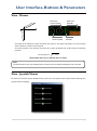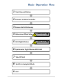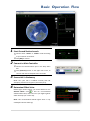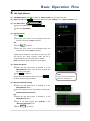
1
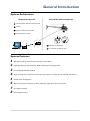
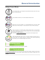
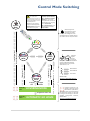
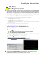
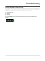
XP3.1 WayPoint Quick Start Manual 1.4 Attention! You will need to be familiar with the correct installation, configuration and operation of the XP3.1 Autopilot before you start using XP3.1 WayPoint. 1| XP3.1 WayPoint Contents READ ME FIRST ................................................................................................................................................. 3 GENERAL INTRODUCTION ................................................................................................................................ 4 SYSTEM ARCHITECTURE ............................................................................................................................................. 4 SYSTEM FEATURES .................................................................................................................................................... 4 MULTIPLE CONTROL MODES ...................................................................................................................................... 5 SOFTWARE INSTALLATION ................................................................................................................................ 6 SYSTEM REQUIREMENTS ............................................................................................................................................ 6 INSTALL DJI GROUND STATION 3.1.X ........................................................................................................................... 6 HARDWARE ASSEMBLY ..................................................................................................................................... 7 WIRELESS DATA-LINK CONNECTION ............................................................................................................................. 7 JOYSTICK MINIMUM REQUIREMENT............................................................................................................................. 8 JOYSTICK CONNECTION.............................................................................................................................................. 8 JOYSTICK CALIBRATION .............................................................................................................................................. 9 JOYSTICK CHANNEL MAPPING................................................................................................................................... 10 USER INTERFACE, BUTTONS & PARAMETERS .................................................................................................. 11 MENU & TOOLS BAR .............................................................................................................................................. 11 VIEW - 3D MAP .................................................................................................................................................... 12 VIEW - MISSION EDITOR ......................................................................................................................................... 13 VIEW - METERS ..................................................................................................................................................... 15 VIEW - JOYSTICK VIEWER ......................................................................................................................................... 15 ALTITUDE OFFSET SETTING ............................................................................................................................. 16 BASIC OPERATION FLOW ................................................................................................................................ 17 1 START GROUND STATION LAUNCH ..................................................................................................................... 18 2 CONNECT TO MAIN CONTROLLER ..................................................................................................................... 18 3 ENSURE HELI IS STATIONARY ............................................................................................................................ 18 4 DETERMINE OFFSET VALUE.............................................................................................................................. 18 5 EDIT FLIGHT MISSION..................................................................................................................................... 19 6 SYNCHRONIZE FLIGHT MISSION WITH HELI ......................................................................................................... 23 7 TAKE OFF HELI ............................................................................................................................................... 23 8 SWITCH TO AUTOPILOT MODE ......................................................................................................................... 23 9 GO!! ........................................................................................................................................................... 23 CONTROL MODE SWITCHING ......................................................................................................................... 24 PRE-FLIGHT SIMULATION ............................................................................................................................... 25 TROUBLESHOOTING ....................................................................................................................................... 26 GROUND STATION SOFTWARE CRASH ......................................................................................................................... 26 2| Read Me First Read Me First Introduction Thank you for purchasing DJI product. Please read the operating instructions thoroughly for proper operation of your new DJI XP3.1 Waypoint. DJI XP3.1 WayPoint is the new DJI flight control system with Ground Station software that enables 3-D map way points editing, flight path planning and real-time flight attitude feedback. This product is specially designed for the purpose of advanced Unmanned-Helicopter operation, BVR (Beyond Visual Range) flying and applications such as surveillance, aerial photography, etc. Based on the existing XP3.1 Autopilot, XP3.1 WayPoint not only ensures stable performance and safety of the helicopter, easy operation for the pilot, but also allows the helicopter to fly automatically according to the flight path set before or modified during the flying process in the Ground Station software. Copyright This product and manual are copyrighted by Dajiang Innovation Technology Co. Ltd. with all rights reserved. No part of this product and manual may be reproduced in any form without the prior written permission of Dajiang Innovation Technology Co. Ltd. No patent liability is assumed with respect to the use of the product or information contained herein. © 2010 Dajiang Innovation Technology Co. Ltd. All Rights Reserved. Disclaimer Dajiang Innovation Technology Co. Ltd. assumes no liability for damage incurred directly or indirectly from the use of this product. Trademarks Google logo is a registered trademark of Google Inc. DJI is a registered trademark of Dajiang Innovation Technology Co. Ltd. Names of products, brands, etc., appearing in this manual are trademarks or registered trademarks of their respective owner companies. 3| General Introduction General Introduction System Architecture Heli with DJI XP3.1 Autopilot Kit DJI WayPoint Basic Kit 1 Ground Station Software & User Guide 2 Laptop 3 Wireless Data-Link (Ground) 4 Wireless Data-Link (Air) 5 3 Position Switch Tx 4 2 3 6 5 DJI XP3.1 Autopilot Kit 6 Transmitter for Heli Control System Features 1 2 3 4 5 6 7 8 Way points editing, maximum 50 way points can be added Flight path planning and modifying, before and during the flying process Real-time flight attitude feedback Meters provided to read real-time helicopter information, including velocity, attitude and altitude. Validity check of flight path More secured communication protocol, automatic justification upon loss of data. Pre-Flight Simulation Joystick aided control 4| General Introduction Multiple Control Modes Tx Manual Mode Pure manual control, your helicopter electromechanical system will react to your R/C Tx command directly. Ensure attitude consistency in a no GPS condition with R/C Tx aid. Attitude Mode Autopilot Mode Joystick Mode Way point Mode Allow users to fly the helicopter in an easily-operational way, and even enable stable control of the helicopter in a few minutes for learners and first-time-flyers. With all the features in autopilot mode, enable multiple choices in control devices besides traditional R/C Tx. The transmission distance can also be extended beyond the range of a traditional R/C Tx. Please refer “DJI XP3.1 Standard Manual” for operation under autopilot mode. 100% unattended flight mode. Preset or real-timely modify your flight mission in Ground Station and remotely upload to helicopter. With flexible programming environment, you can modify the flight mission any time. HOVERING MODE PROTECTION CLASS I Auto-hover your helicopter when R/C Tx communication is unstable. AUTOMATIC GO HOME PROTECTION CLASS II Auto-navigate your helicopter back to pre-set home location when R/C Tx signal is totally lost. Please refer “DJI XP3.1 Standard Manual” for home location setting, otherwise this protection strategy will not be activated. 5| Software Installation Software Installation System Requirements Operating System: Windows XP or above Internet Explorer 8 .NET framework 3.5 Google Earth™ Plug-In Install DJI Ground Station 3.1.x 1 2 3 4 5 Insert the DJI Product CD into your CD-ROM, an Autorun window will appear: If you did not install .Net Framework 3.5, IE 8 or Google Earth™ Plug-In, please click on the buttons respectively to install them first, as they are REQUIRED for DJI Ground Station 3.1.x. Click [Install DJI Ground Station 3.1.x], follow the installation guide, and install the Ground Station software. Before using Ground Station to control your helicopter, you need to configure your XP3.1 Autopilot correctly, click [Install DJI XP Configure 1.3.3] to install the configuration software. For configuration details, click [Browse the CD], and read the “XP3.1 Standard Manual” Click [Exit] after you finish all the installation. 6| Hardware Assembly (Wireless Data-Link) Hardware Assembly Wireless Data-Link Connection Adapter Please use Port 4 Antenna Wireless Data-Link (Air) Power connection Main Controller Data connection To Helicopter Power connection Antenna Wireless Data-Link (Ground) Male Male OR Female USB-to-RS232 Cable To Ground Station RS232 Cable Connect to you computer 7| Hardware Assembly (Joystick) Joystick Minimum Requirement Joystick control based on a third party hardware controller, you can choose your preferred device based on the two types of joystick indicated below. Type 1: Traditional R/C style flight simulation controller; or your R/C Tx with a third party simulator link Type 2: Linear single stick 3D controller Technical requirement 4 linear control channel USB connection Type 1 Real Flight® InterLink™ Plus Controller Type 2 Logitech® Extreme™ 3D Pro Joystick Joystick Connection Refer to the user manual of the specific controller / Joystick you choose, and ensure the USB cable is properly connected. Please ensure the Joystick is properly connected physically, do not break the joystick connection when Joystick Mode is activated. 8| Hardware Assembly (Joystick) Joystick Calibration CAUTION You must & only do this procedure every time before you take off your heli !! Menu list [Joystick][Choose Joystick] 1 Select a proper joystick in [Joystick][Choose Joystick], as indicated above. 2 Click [Joystick][Calibration], you will see popup windows shown asbelow. NEXT NEXT For Type 1 As directed, place all trim levers (for physical fine turnning) in their neutral, or centered position. Click [Next] to continue. Center all the sticks . Click [Next] to continue. Move all of the sticks through their complete range of motion several times. When completed, click [Finish]. For Type 2 For Type 2 controller, you might not have these physical fine turning levers. Click [Next] to continue. Center you stick including your throttle. Click [Next] to continue. Move the sticks through its complete range of 3D motion several times, including pitch. When completed, click [Finish]. 3D Channel Throttle Channel Sketch of 3D Joystick 9| Hardware Assembly (Joystick) Joystick Channel Mapping CAUTION You must & only do this procedure every time before you take off your heli !! Menu list [Joystick][Channel Mapping] Click [Joystick][ Channel Mapping], you will see popup windows shown as below. Real-Time Joystick channel value feedback Reverse Mapping Each control channel can be reversed, and mapped to one of the control objects which will be listed in corresponding drop down boxes. These control objects are ‘Roll’, ‘Elevator’, ‘Yaw’ & ‘Collective Pitch’, they represent the motion status of you helicopter, as in the figures below. Where the ‘+’ represents positive channel value, ‘-’ represents negative channel value. Push your joystick, and the channel value feedback will tell whether it matches with our suggested joystick control direction or your own settings, and then make your adjustments. For Type 1 controller, please refer to the controller’s manual. For safety reasons, all previously used settings will be cleared whenever you re-enter [Joystick Channel Mapping], and you will need to carefully repeat the steps above. Roll Elevator Roll (+) Yaw Collective Pitch Elevator (+) Roll (-) Elevator (-) Yaw (+) Yaw (-) Collective Pitch(+) Collective Pitch(-) 10 | User Interface, Buttons & Parameters User Interface, Buttons & Parameters Menu & Tools Bar Calculate altitude offset * Serial port select Click to connect with main controller Disconnect Connected Edit Mode Layout * Mission Pause * Flight Mode Layout * Operation Mode Indicator ( Default in [Real Mode] ) CAUTION CAUTION Pre-Flight Simulation Altitude Offset Setting File You can save your flight mission in your local hard drive or flash-disk. This features allows you load your frequently use mission without edit them every time. View Select the equipments which you want to be display. Set If the heli model can not be display ( load from your local device ), select [Use Online Heli]. It might take few minutes depends on your network conditions. Users’ Tip: Joystick Simulate For real flight execution Only for on land tutorial The simulation features aims to help you familiar with this software. You can only use the simulation Mode on land.* Note: * Only available if correctly connected with DJI Autopilot main controller. 11 | User Interface, Buttons & Parameters View - 3D Map The coordinate of the location mouse is pointed at. ** Real-Time coordinates of Helicopter. * Tick if you want to see Heli Track. Tick if you want to see Path Extrude during mission editing. Way point altitude Tick if you want to see Map Details in text. Tick if you want to use Map Navigator . Index number of way point Zoom In the map to find heli location.* Zoom Out the map to find your Home location. *** Way point Current Heli altitude Head Under editing Not selected Path Color Before Mission Execute After mission checked. If collision happens between way point path and mountain, these path will be shown as red. If path length longer than 10 km, it will be shown as yellow. Blue one is normal. Helicopter model Tail Mission Editing Projection line of way Point-to-Point distance point, not for scale between two way points Path Color During Mission Execution All the paths including way point index will be shown as red during mission execution. Note: * Only available if correctly connected with DJI Autopilot main controller. ** Here the altitude will be re-generated depending on the altitude offset value you set. *** Only available after Mission Execute, the Home location is where the Start Way point located. 12 | User Interface, Buttons & Parameters View - Mission Editor SYNCHRONIZE upload the mission to Main Controller. Go to Execute Fixed Mission. Re-Edit the Fixed Mission. Reload Mission from Main Controller. Mission Status Indicator which red light indicating the current status. Properties for Editing Mission are writeable; Fixed Mission are read only. ●Latitude & Longitude unit is indegree. ●Altitude unit in meters. ●Speed is velocity from previous point to current point which is limited under 15 m/s. ●HoldTime is the time to stay at this way point, unit in second. ●TimeLimit is a down-count timer for the maximum time-of-flight from previous way point to current way point, terminate the way point if time out even this way point has not been reached. Unit in second. 13 | User Interface, Buttons & Parameters Description of selected item. Altitude decrement 10m per click.① Altitude decrement 1m per click. Altitude increment 10m per click. Altitude increment 1m per click. Mission Check, this feature can help you to avoid most of the way point edit error, such as Mountain-Flight Path collision. ② Delete way point by selecting them, then click Add new way point by click . , then click on the map. Or Ctrl + on the map. Editing Mission Menu. Begin Edit. Cancel All edited way points. Fixed Mission Menu. Set Altitude Offset, Unit in meters. You will see this instead if selected. ●IsPatrol is the selection of mission execution mode: False, one time execute; True, for repeatly flying from start way point to end way point. ●StartWayPoint defines the first way point your heli going to after you click “GO”. Select the proper way point index number listed. (Default value is 0) 【Note】 ① You can also adjust the altitude of your way points by following buttons. ② Click Error Message: check your way point. Pass Message: you can go on. 14 | User Interface, Buttons & Parameters View - Meters Real-Time Vertical speed ed pe S rth No (VN) Real-Time Attitude Vertical Speed (Ve) East Speed (VE) Real-Time Ground speed Real-Time Altitude According to the definition of GPS coordinate (As shown in the upper left graph), an arrow pointing down stands for a positive vertical speed. The Ground speed is not direction oriented, but a value calculated from VN & VE with the following equation. Ground speed = VN 2 + VE 2 All the speed unit is in m/s, Altitude unit is in meters. Note: The above features are only available when correctly connected with DJI Autopilot main controller. View - Joystick Viewer To check the real-time Joystick feedback value, please use the joystick viewer which without affecting the joystick channel mapping. 15 | Altitude Offset Setting Altitude Offset Setting CAUTION Altitude Offset Setting GIS database (Google Earth™) is not precise, and Flight Path Mountain collision checking feature is performed based on this database, which is not real-time or up-to-date. Some landform might be different from what you see in the 3D-Map such as new buildings. Here the Google Earth™ plug-in is only for the purpose as a general landform browser, for quick way points positioning without much safety guarantee. We are using pressure sensor for altitude sensing, the result varies according to weather. Therefore, you might have different altitude values on the same location at different times. However, its relative height is far more precise than absolute altitude information in GIS. Due to above problems, the following method for relative flight height calculation would be most reliable. a) Record the heli altitude before take-off, LGound b) The relative flight height from LGound to each way points = way point altitude - LGound Please keep in mind that this method is the most reliable way for flight path collision prediction. The Altitude Offset value given was only for the purpose to avoid visual confusion, such as in Case 1 shown below. The helicopter represented by the red point was located on the ground in real world but floating in the sky within 3D-Map. You have to give a negative offset value to reduce the helicopter altitude for visually effect only. The calculate altitude offset function will give you a suggestion for offset setting but not guaranteed to be correct. Because if the helicopter is landed on the roof of the building as in Case 2 in figure shown below, and the building information will not appear in GIS database, which means you cannot use the same method as in Case 1. You should calculate this offset value with a known or estimated building height. We highly recommend you to consider the relative flight height we discussed above during your flight mission editing. IN 3D-MAP IN REAL WORLD Longitude tit ud La Altitude e After set-offset e tit ud La Longitude e tit ud La tit ud La Altitude e Longitude Altitude tit ud La Altitude Altitude Longitude e tit ud La Case 2 Heli stay on the roof of building Longitude Altitude Case 1 Heli stay on the ground e Before set-offset Longitude 16 | Basic Operation Flow Basic Operation Flow 1 Start Ground Station 2 Connect to Main Controller 3 Ensure Heli is Stationary 4 Determine Offset Value CAUTION 5 Edit Flight Mission CAUTION 6 Synchronize Flight Mission With Heli 7 Take Off Heli 8 Switch to Autopilot Mode 9 Go!! Altitude Offset Setting Altitude Offset Setting 17 | Basic Operation Flow 1 Start Ground Station Launch 1 Choose either “online” or “offline” mode according ○ to your network connection. 2 Click [OK] to confirm. ○ 2 Connect to Main Controller 1 Choose the communication port in the drop down ○ box. 2 Click [Connect] button on the upper left corner, to ○ connect with the DJI Autopilot main controller. 3 Ensure Heli is Stationary Make sure your heli is installed correctly with DJI Autopilot, placed on level ground, and ready to fly. 4 Determine Offset Value Before flight mission editing, you should determine the Altitude Offset. Click to find our recommended altitude offset value, and record it in your flight log book which will help you in later step. CAUTION Altitude Offset Setting Note: This recommended altitude offset value is only valid before the heli takes off. 18 | Basic Operation Flow 5 Edit Flight Mission (1) Edit Mode Layout. Click (2) Begins to edit. Click , you will find “Mission Editor” on the right hand side. , the Mission Status will show “Editing” in the “Status Indication” box. CAUTION Altitude Offset Setting (3) Set offset value. 1 Type your offset value in ○ 2 Then click [Set Offset]. ○ (4) Add way points. 1 Click ○ 2 Left click ○ your mouse on the 3D-Map where the locations you want to add a way point. OR 1 Press Ctrl and hold. ○ 2 Left click your mouse on ○ the 3D-Map where the locations you want to add a way point. Repeat above procedure if you wish to add more new way points. The initial waypoint index will be 0, incremented by 1 each new way point is added. Note: A maximum of 50 way points can be added. (5) Delete way points. 1 Select ○ the way point either in 3D-Map or in the Editing Mission Menu. The currently selected way point is in color green. 2 Click ○ to delete it. Repeat above procedure to delete more. Click to delete all the way points added. Note: The currently selected way point is in color green. (6) Way point altitude setting. 1 Select ○ the way point either in 3D-Map or in the Editing Mission Menu. 2 Edit the altitude of each way points by clicking the ○ [Altitude Calibration buttons]. OR 1 Select ○ the way point either in 3D-Map or in the Editing Mission Menu. 2 Type ○ in the precise figure after “Altitude” in the “Way Point Properties” box. 3 Press ○ Enter to confirm. 19 | Basic Operation Flow (7) Speed setting. This Speed is the velocity of heli flying to specific way point editing. (Unit in m/s) 1 Select ○ the way point either in 3D-Map or in the Editing Mission Menu. 2 Type in the precise figure after “Speed” in the “Way ○ Note: The system default speed is 4m/s, and the maximum speed allowed is 15m/s. Point Properties” box. 3 Press ○ Enter to confirm. (8) Turning Mode setting There are two different turning modes for the heli at each way point: Stop and Turn/ Coordinated Turn. The default turning mode in the system is ‘Stop and Turn’. You can change it according to the following steps. 1 Select ○ Note: The Hold Time in way point property will be deactivated if Coordinated Turn chose. the way point either in 3D-Map or in the Editing Mission Menu. 2 Click ○ or to select the desired turning mode. The selected turning mode will appear in ‘TurnMode’ box of way point properties. You can also change the turning mode in the way point properties window discussed in previous sections. (9) Time Limit setting A way point time-limit timer, will set time limit between two way points, and terminate the flying upon time out even the way point has not been reached. (Unit in second) 1 Select ○ the way point either in 3D-Map or in the Note: You have to estimate the maximum time spent to approaching current editing way point from previous way point. Editing Mission Menu. 2 Type in the precise maximum time of flying between ○ two way points (in seconds) after “TimeLimit” in the “Way Point Properties” box. 3 Press ○ Enter to confirm. (10) Hold Time setting Sets the time to stay in a particular way point.(in second) 1 Select ○ the way point either in 3D-Map or in the Editing Mission Menu. 2 Type in the precise time to stay in a way point (in ○ seconds) after the “TimeHold” in the “Way Point Properties” box. 3 Press ○ Enter to confirm. 20 | Basic Operation Flow (11) Patrol or Not selection 1 Click ○ , you will see Mission properties. 2 make ○ a selection from the drop down box after “IsPatrol” for mission execution mode: “False”, one time execute; “Ture”, repeating. Note: the default status is “False”. (12) Start way point selection 1 Click ○ , you will see Mission properties. 2 make ○ a selection from the drop down box after “StartWayPoint” for start way point from the existing way point indexes. Note: the default start way point index is”0”. (13) Mission Save 1 Click [File] ○ 2 Click [Save Mission As] to save your mission edited, ○ choose a proper name with extension ‘.mis’. For Example: DJI_Mission_20100101.mis Note: The Altitude offset value will not be saved in mission file. You must set it every time!!! 3 Press [Save] to confirm. ○ (14) Mission Load 1 Click [File] ○ 2 Click [Load Mission] to load your mission saved, choose your mission file with extension ‘.mis’. ○ 3 Press [Open] to confirm. ○ Mountain Mountain When you set the waypoints for the helicopter to climb a mountain, please make sure that you leave enough distance between the helicopter and the mountain to avoid collision caused by heli inertial. La tit ud Altitude e Please note that when you set a way point above a lake/sea/river, the default altitude the map identifies will be at the bottom of the lake/sea/river. Please reset your own altitude for the way point to avoid water-collision. Users’ Tip: Longitude 21 | Basic Operation Flow Examples for Way Point turning mode Way point 1: Stop and Turn 0 Users’ Tip: Way point 1: Coordinated Turn 1 0 1 2 2 Examples for Mission/Way Point properties setting A1/A2: Selection for the state of “IsPatrol”, and “StartWayPoint”. B1: If the “TimeLimit” timer of a waypoint has been set and time out before heli approached this way point, your heli will ignore this way point and turn to the next flight path. B2: If the “HoldTime” timer of a waypoint has been set, your heli would stay hovering on this waypoint until “HoldTime” timer was time out. Mission properties: IsPatrol : Ture StartWayPoint : 1 Mission properties: IsPatrol : False StartWayPoint : 0 Initial Position 0 1 Initial Position 0 1 3 2 Stop here, and stay hovering 3 2 Way Point properties of Way point 1: … HoldTime: 4 second TimeLimit: 100 second 0 0s 0 0s 0 0s 1 75s 100s 100s A1 A2 B1 B2 Way Point properties of Way point 1: … HoldTime: 15 second TimeLimit: 200 second 0 0s 75s 0s 1 15s 1 1 2 0 0s 75s 1 0s 15s 2 22 | Basic Operation Flow 6 Synchronize Flight Mission with Heli Click on the upper left corner of the Mission Editor to send flight mission to the DJI Autopilot main controller. After successfully synchronized, the mission is ready executing. After synchronized, you still can re-edit your mission by “Re-Edit”, click to do so. Then the mission editor will return to the state as as we told in previous section”5 Edit Flight Mission” 7 Take off heli After finishing all the above steps, take off your helicopter in Manual Mode, and hover it at a suitable height. 8 Switch to Autopilot Mode Note: Refer “DJI XP3.1 Standard Manual” for Manual Mode / Auto Mode switching of your DJI Autopilot System, and also the Manual of your R/C Transmitter (Tx). 3 Position Switch Switch to the Autopilot Mode on your Tx. 9 Go!! Click Tx 6 in the “Mission Editor”, and the helicopter will fly automatically according to the path you have set in the flight mission. For Flight Mode Layout, Click , you will find “meter” on the bottom side as shown below. Users’ Tip: After mission executed, you still can re-edit your mission by [Edit], click , then click in mission editor to do so. Then the mission editor will return to the state as we told in previous section”5 Edit Flight Mission”. After mission executed, you can pause the mission by [Pause], click and stay hovering. Click , the helicopter will slow down , the helicopter will resume the un-finished mission. 23 | Control Mode Switching Control Mode Switching CAUTION Preparation 1►Select a proper joystick in [Joystick][Choose Joystick]. For Joystick Mode ▲Keep your R/C Tx power on and successfully connected with Rx either before or after DJI system power on. 2►Do Calibration & Channel Mapping for your Joystick every time before you take off the helicopter if you are going to use Joystick Mode. ▲ Make sure your Joystick is properly connected physically. Joystick Mode 3►In Waypoint Mode, pause the mission to activate the Joystick Mode. ▲Manual Mode should be the initial mode for DJI system. With the support of Ground Station system, operations of greater flexibility and intelligence can be achieved. Based on a friendly GUI, all you need to do is to click your mouse. Pa u m se t iss he W ion ith Jo R ys m esu tic k a issio me n the ct ive n io iss & d M nt ute Se ec Ex R/ C M AN Tx Tx Signal Lost PROTECTION CLASS I Tx Signal Resume HOVERING MODE Switch to R/C MAN MA N R/C R/C AT TI TI AT Tx Signal Lost Tx Signal Resume R/C Attitude Mode Tx Signal Lost Time > 10s PROTECTION CLASS II Holds the highest priority Tx control of the system. You can switch between control modes (Manual/Auto/ Attitude) easily via a 3-position switch on the r/c Tx. 3 Position Switch Manual Mode Tx Signal Lost Tx Signal Resume Autopilot Mode R/C MAN If Tx Signal Resume R/C AUTO TO AU R/C Joystick Signal Lost Joystick Signal Resume Way point Mode AUTOMATIC GO HOME R/C MAN Manual Mode R/C ATTI Attitude Mode R/C AUTO Auto Mode Please refer “DJI XP3.1 Standard Manual” Protection under fail- s a f e Strategy, eliminates system failure due to Tx/Rx failures, and ensures safety of the helicopter & the accessories related. You will need to configure the settings in the XP3.1 Autopilot Configuration Software, please refer “DJI XP3.1 Standard Manual” 24 | Pre-Flight Simulation Pre-Flight Simulation CAUTION Pre-Flight Simulation Our system support Pre-Flight Simulation which only aims to help you get familiar with the Ground Station software. A successful flight under simulation mode does not guarantee your helicopter to work successfully in real world, since it is only a virtual environment based on the assumption that your helicopter is working under perfect condition with infinity power supply, favorable weather, and also that the GIS & GPS are giving 100% correct and precise information. The helicopter physical model in simulator might not perform the same characteristic as your real helicopter. Ensure the following requirements whenever during/before Simulation Mode: 1) You MUST NOT take off your helicopter. 2) You MUST NOT turn on your helicopter engine. 3) You CAN disconnect the power supply for electric motor, or disconnect the throttle control servo motor for fuel engine. Otherwise, wrong operation could result in serious personal injuries. Please follow the steps strictly for the use of Simulation Mode: 1 ○ 2 ○ 3 ○ Perform step1 & step2 from the <Basic Operation Flow> Section. Click [Simulate][Simulation Mode OnOff], you will see a prompt “Top warning” window. Browse the 3D Map, and record the coordinates in your clipboard: 1. Press Ctrl and hold. 2. Right click your mouse on the location you want to perform the simulation. 3. Select [Copy mouse Lati/Longi/Alti to Clipboard] 4 ○ Click [Simulate][Set sim heli location], you will see a prompt “Simulated Heli Location Setting” window. Select [From clipboard] and confirm by click [Set] 5 ○ Click [Simulate][Simulate] to turn on Simulation Mode. Now, your system is working under Simulation Mode!!! 6 ○ Perform step 5, 6 & step 9 from the <Basic Operation Flow> Section. We highly recommend Simulation Mode for practicing purpose for flight mission edit, try to get familiar with all the operations of your Ground Station as much as you can 25 | Troubleshooting Troubleshooting Ground Station Software Crash Ground Station Software Crash will not affect the helicopter under mission executing. The helicopter will keep going on the flight mission edited even the Ground Station Software crash. The Ground Station Software can be launched again, but loss of the following information will happen: 1. Altitude Offset value 2. Heli tracks 3. Way points Click on the “Reload” button to retrieve the previously set way points from the DJI Autopilot main controller. 26 |