1
SECTION: N - Assembling and disassembling
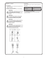
BPV(S)(C)(F)(V):
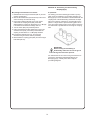
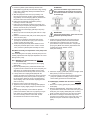
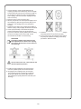
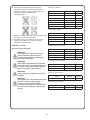
M-4) Change of terminal box connection:
1. Disassemble the hexagon head bolts (901.01) and the
coupling guards (681).
2. Remove the bolts/screws (901.02/914.02) of the motor
and if necessary the electrical wiring.
3. Lift the motor (800) a little with a tyre lever placed
underneath the coupling shell (862). If this fails
disassemble the coupling as described in xx.x.x BPV(S)
F 32/45/65 with mechanical cartridge seal 197.
4. Turn the motor (800) into preferred position.
5. Fasten the bolts/screws (901.02/914.02) of the motor
crosswire and equally, if necessary reassemble the
coupling as described in xx.x.x BPV(S)F 32/45/65
with mechanical cartridge seal 197, reconnect the
electrical wiring and check rotation (clockwise).
6. Reassemble the coupling guard (681) and the hexagon
head bolts (901.01).
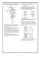
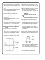
N-1) General:
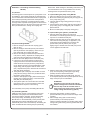
The starting point of the following procedure is a pump
taken out of an installation. The hydraulic assembly of a
BPV(S) pump is to be assembled or disassembled with the
coupling side of the shaft directing downwards. A simple
aid for this method is a jaw bench, provided with tension
plates. For larger series a special mounting plate can be
used. The shaft (coupling side) is to be placed in the bush
and locked with a pin diameter 5mm through the coupling
hole.
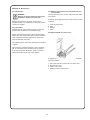
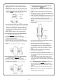
IMPORTANT
Before starting the assembling or
disassembly, make sure the correct type of
O-rings and shroud are present!
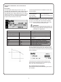
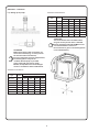
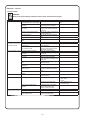
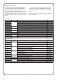
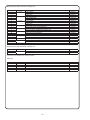
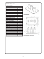
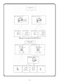
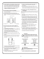
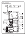
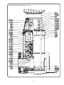
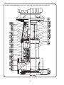
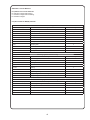
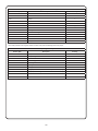
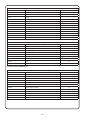
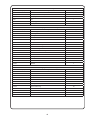
For determination of the correct O-ring and shroud to be
used for the assembling and disassembling of the
BPV(S)(C)(F)(V), carefully select them using the
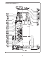
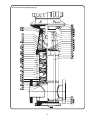
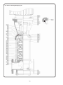
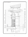
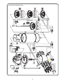
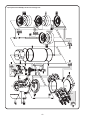
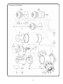
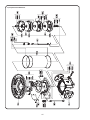
proceeding diagrams.
21