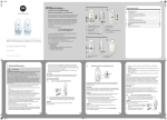
1
CONTENTS CHAPTER 1 PRODUCT INFORMATION ...................................................................................................................... 1 1.1 Designation .................................................................................................................................................... 1 1.2 Nameplate ...................................................................................................................................................... 1 1.3 General Specifications ................................................................................................................................... 2 CHAPTER 2 WIRING ..................................................................................................................................................... 3 2.1 Typical Wiring ................................................................................................................................................. 3 2.2 Terminals........................................................................................................................................................ 5 CHAPTER 3 EASY SETUP ............................................................................................................................................ 7 3.1 Logic of Control .............................................................................................................................................. 7 3.2 Step By Step Setup ........................................................................................................................................ 9 CHAPTER 4 TROUBLESHOOTING ............................................................................................................................ 22 4.1 Faults And Solutions .................................................................................................................................... 22 4.2 Common Symptoms And Diagnostics ......................................................................................................... 25 CHAPTER 5 FUNCTION CODE TABLE ...................................................................................................................... 26 5.1 General Function Codes .............................................................................................................................. 26 5.2 Monitoring Function Codes .......................................................................................................................... 42 CHAPTER 1 PRODUCT INFORMATION 1.1 Designation MD210 X X.X X MD210 series AC drive Mark Built-in Braking Unit B Yes Mark Voltage Class S Single-phase 220 V 2T Three-phase 220 V Mark 0.4 0.7 1.5 2.2 T Three-phase 380 V Applicable motor, [kW] 0.4 0.75 1.5 2.2 1.2 Nameplate Nameplate AC drive model Rated input Rated output S/N code MODEL: MD210T0.7B 3~380-440 V, 3.4 A, 50/60 Hz INPUT: OUTPUT: 3~0-440 V, 2.1 A, 0-500 Hz, 0.75 kW S/N: 013010034CC00011 Barcode Manufacturer Suzhou Inovance Technology Co.,Ltd. Page 1 of 43 1.3 General Specifications Single-phase 220 VAC ƹ Voltage Class Drive Model Three-phase 220 VAC ƹ MD210 MD210 MD210 MD210 MD210 MD210 MD210 MD210 MD210 MD210 MD210 MD210 S0.4B S0.7B S1.5B S2.2B 2T0.4B 2T0.7B 2T1.5B 2T2.2B T0.4B T0.7B T1.5B T2.2B 2 / 2 / 1 2 158 / 148 158 Frame Size 1 1 H [mm] 128 W [mm] Dimension ƾ 108 D [mm] 148 158 / 148 A [mm] 96 Drive Input B [mm] 118 Rated Input Voltage Rated Input Current (A) Single-phase 220 VAC, -15 to 20% Three-phase 220 VAC, -15 to 20% Three-phase 380 to 440 VAC, -15 to 20% (187 to 264 VAC) (187 to 264 VAC) (323 to 528 VAC) 5.4 8.2 14.0 23.0 3.4 5.0 5.8 10.5 1.9 3.4 5.0 5.8 50/60 Hz, f5% (47.5 to 63 Hz) Rated Input Frequency [kW] 0.4 0.75 1.5 2.2 0.4 0.75 1.5 2.2 0.4 0.75 1.5 2.2 [HP] 0.5 1 2 3 0.5 1 2 3 0.5 1 2 3 Output Current, [A] 2.3 4.0 7.0 9.6 2.1 3.8 5.1 9.0 1.5 2.1 3.8 5.1 Power Capacity, [kVA] 1.0 1.5 3.0 4.0 1.0 3.0 4.0 5.9 1.2 1.5 3.0 4.0 Applicable Motor Drive Output Three-phase 380 VAC Overload Capacityƿ 120% for 1 hour & 150% for 60 Sec &180% for 2 Sec Max. Output Voltage Three-phase 220 VAC Three-phase 220 VAC Three-phase 380 VAC (proportional to input voltage) (proportional to input voltage) (proportional to input voltage) Max. Output Frequency Recommended Braking Resistor 500 Hz [kW] ≥ 0.08 ≥ 0.08 ≥ 0.1 / ≥ 0.15 ≥ 0.15 ≥ 0.25 / ≥ 0.15 ≥ 0.15 ≥ 0.15 ≥ 0.25 [Ω] ≥ 200 ≥ 150 ≥ 100 / ≥ 150 ≥ 110 ≥ 100 / ≥ 300 ≥ 300 ≥ 220 ≥ 200 Cooling Method Air Fan Air ƹ: Drives of 220 VAC power supply (both single-phase and three-phase) are being developed. ƿ: At 6 kHz carrier frequency without derating ƾ: Dimensions are shown as below: : $ Fan Air Fan + % 4×Ø5 ' Page 2 of 43 CHAPTER 2 WIRING 2.1 Typical Wiring Wiring of Three-phase 220/380 VAC Power Supply Braking resistor (optional) MCCB R Power supply Three-phase 220V/380V 50/60 Hz (-) S P(+) BR MD210 T U V W J3 9 OP is connected to +24V in default, please pay attention to jumper J3 COM OP FWD +24V DI1 FJOG DI2 RESET DI3 Multi-reference terminal 1 Multi-reference terminal 2 AO1 GND Analog output (Running frequency) DI4 DI5 COM +10V Analog input (Frequency source) +24V J12 GND NC R485 485J4 RS485 NC R485 485+ AI1 GND T/C T/B T/A Multi-function relay output (Fault output) Page 3 of 43 Wiring of Single-phase 220 VAC Power Supply Braking resistor (optional) MCCB Power supply Single-phase 220V 50/60 Hz L1 ( - ) L2 P(+) BR MD210 U V W OP is connected to +24V in default, please pay attention to jumper J3 J3 9 COM OP FWD +24V DI1 FJOG DI2 RESET DI3 Multi-reference terminal 1 Multi-reference terminal 2 +24V AO1 GND DI4 DI5 J12 NC R485 COM +10V Analog input (Frequency source) Analog output (Running frequency) GND 485- J4 NC R485 485+ RS485 AI1 GND T/C T/B T/A Multi-function relay output (Fault output) Page 4 of 43 2.2 Terminals 9 Terminals of Main Circuit Table 2-1: Main circuit terminals of the single-phase Terminal Terminal Name Description L1, L2 Single-phase power supply input terminals Connect to the single-phase 220 VAC power supply. P(+), (-) Positive and negative terminals of DC bus Common DC bus input point. P(+), BR Connecting terminals of braking resistor Connect to a braking resistor. U, V, W AC drive output terminals Connect to a three-phase motor. Grounding terminal Must be grounded. Table 2-2: Main circuit terminals of the three-phase Terminal Terminal Name Description R, S, T Three-phase power supply input terminals Connect to the three-phase 220/380 VAC power supply. P(+), (-) Positive and negative terminals of DC bus Common DC bus input point. P(+), BR Connecting terminals of braking resistor Connect to a braking resistor. U, V, W AC drive output terminals Connect to a three-phase motor. Grounding terminal Must be grounded. Page 5 of 43 9 Terminals of Control Circuit Terminal Terminal Name Description +10V-GND +10 VDC power supply Provide +10 VDC power supply to external unit. Usually, it provides power supply to external potentiometer with resistance range of 1kΩ to 5 kΩ. Max.. output current: 10 mA. +24V-COM +24 VDC power supply Provide +24 VDC power supply to external unit. Usually, it provides power supply to DI/DO terminals and external sensors. Max. output current: 200 mA. OP Input terminal of external power supply Connect to +24 VDC by default. Whether it connects to +24 V or COM is decided by jumper J3. When DI1 to DI5 need to be driven by external signal, OP needs to be connected to external power supply and be disconnected from +24 VDC. AI1-GND Analog input 1 Input voltage range: 0 to 10 VDC. Impedance: 22 kΩ. DI1-COM Digital input 1 DI2-COM Digital input 2 DI3-COM Digital input 3 DI4-COM Digital input 4 DI5-COM High-speed pulse input Besides features of DI1 to DI4, it can be used for high-speed pulse input. Max. input frequency: 20 kHz. AO1-GND Analog output 1 Output voltage range: 0 to 10 VDC. 485+-485- Communication terminal MODBUS protocol. Baud rate: 300 to 115200 bps. Max. nodes: 32. Terminal resistance jumpers: J4 and J12. T/A-T/B Normally closed terminal T/A-T/C Normally open terminal Optical coupling isolation, compatible with dual-polarity input. Impedance: 2.4 kΩ. Input voltage range: 9 to 30 VDC. Contact driving capacity: 250 VAC, 0.2 A, COSø=0.4; 30 VDC, 1 A. Page 6 of 43 CHAPTER 3 EASY SETUP 3.1 Logic of Control 9 Complete Timing Diagram Fr equency F0-08 [x.x Hz] F0-18 Fr equency F0-17 F6-09 F6-08 [x.x Sec] [x.x% ] [x.x% ] [x.x Sec] F6-11 [ x.x Hz]: default 0.0 Hz DC injection braking 2 frequency threshold output command F6-04 [x.x Sec] F6-03 [x.x Hz] F6-08 [x.x% ] F6-09 [x.x% ] Time 0 ON DI 1 For war d OFF ON IGBT's Active OFF 100% F6-06 [ x.x Sec]: F6-13 [ x%]: DC injection braking 1 active time(if F6-00=0) DC injjection braking 2 level F6-14 [ x.x Sec]: DC injection braking 2 active time Pre-excitation active time (if F6-00=2) DC Injection/ Pr e-excitation 40% 20% F6-05 [ x%]: F6-12 [ x.x Sec] (default: 0.0 Sec) DC injection braking 1 level (if F6-00=0) DC injection braking 2 delay time Pre-excitation level (if F6-00=2) 0% 100% Motor Cur r ent 50% 0% Stages t1 t2 t3 t4 t5 t6 t8 t9 t7 Page 7 of 43 9 Timing Diagram Description Event Description Function code Status Inhabit t1 -The AC drive waits for the RUN signal. ----- t2 -The AC drive receives the Forward RUN command. ----- -The IGBT becomes active. ----- -DC Injection Braking 1/Pre-excitation is enabled if F6-06 > 0. (if F6-00 = 0, it is "DC Injection Braking 1"; if F6-00 = 2, it is "Pre-excitation") t3 -DC Injection Braking 1/Pre-excitation is disabled. -The startup frequency becomes active if F6-04 > 0. F6-05 RUN F6-06 ----F6-03 RUN F6-04 t4 -The startup frequency becomes inactive. ----- - The motor ramps up to the expected frequency. F0-17 - S-curve active F6-08 RUN F6-09 t5 -Motor runs at expected frequency. F0-08 t6 -The Forward RUN command is cancelled. ----- -The motor ramps down to zero frequency. F0-18 -S-curve active F6-08 RUN RUN F6-09 t7 -The frequency output command reaches the DC Injection Braking 2 frequency threshold. F6-11 -The IGBT shall become inactive if DC Injection Braking 2 delay time is not zero. F6-12 -After the delay time set in F6-12, the IGBT becomes active again t8 -DC Injection Braking 2 is enabled if F6-14 > 0 RUN (if F6-12 = 0) Inhabit (if F6-12 > 0) ----F6-13 RUN F6-14 t9 -DC Injection Braking 2 is disabled. ----- -The IGBT turns inactive. ----- Inhabit Page 8 of 43 3.2 Step By Step Setup 9 Setup Flowchart Refer to Chapter 1 and 2 Check nameplate and wiring Apply main power to AC drive Get familiar with keypad 1 Set motor parameters 2 Set frequency reference 3 Set operation mode 4 Set start mode 5 Set stop mode 6 Set acceleration and deceleration time 7 Set DI and DO if needed 8 Set startup frequency if needed 9 Set S-curve if needed 10 Set DC injection braking if needed 11 Set pre-excitation if needed 12 RUN! Check motor rotation and machine travelling direction Refer to User Manual Check motor current Refer to User Manual Any problem, refer to Chapter 4 “TROUBLESHOOTING” Page 9 of 43 9 Step 1: Get Familiar With Keypad Overview Indicators LED display Increment key Programming key Multi-function key Confirm key Decrement key Shift key RUN key Stop/Reset key Indicators FWD/REV : It indicates forward or reverse rotation. OFF indicates forward rotation and ON indicates reverse rotation. TUNE/TC : Reserved. REMOTE : It indicates whether the AC drive is operated by means of keypad, terminals or communication. OFF indicates keypad control, ON indicates terminal control, and blinking indicates communication control. RUN/ERR , : It indicates the state of the AC drive. OFF indicates the stop state, ON (green) indicates the running state, and ON (red) indicates the faulty state. LED Display The 5-digit LED display is able to display the frequency reference, output frequency, monitoring data and fault codes. Page 10 of 43 Keys On Keypad Key Key Name Function Programming Enter or exit Level I menu. Confirm Enter the menu interfaces level by level, and confirm the parameter setting. Increment Increase data or function code. Decrement Decrease data or function code. Shift Select the displayed parameters in turn in the stop or running state, and select the digit to be modified when modifying parameters. RUN Start the AC drive in the keypad operation mode. Stop/Reset Stop the AC drive when it is in the running state and perform the reset operation when it is in the faulty state. The functions of this key are restricted by F7-02. Multifunction Perform function switchover (such as quick switchover of command source or direction) according to the setting of F7-01. Function Code Parameter Name Setting Range Unit Default F7-01 MF.K key function selection 0: MF.K key disabled 1: Switchover from remote control (terminal or communication) to keypad control 2: Switchover between forward rotation and reverse rotation 3: Forward jog 4: Reverse jog 5: Individualized parameter display N.A. 0 0: STOP/RESET key enabled only in keypad control 1: STOP/RESET key enabled in any operation mode N.A. 1 F7-02 STOP/RESET key function Commission Page 11 of 43 Keypad Operation F0 U0 AC … A2 A1 FP F0 27 50.00 F0 ENTER PRG F0 02 F0 01 F0 27 PRG 2 ENTER 1 0 F0 03 2 save the value 1 … PRG F1 F0 U0 AC … … ENTER PRG ENTER … F0 02 A2 A1 FP … F1 F0 PRG Function Codes Arrangement Function Code Group Description Remark F0 to FP Standard function code group Standard function parameters A1 to AC Advanced function code group AI/AO correction U0 Running state function code group Display of basic parameters Page 12 of 43 9 9 Step 2: Set Motor Parameters Function Code Parameter Name Setting Range Unit Default F1-00 Motor type selection 0: Common asynchronous motor 1: Variable-frequency asynchronous motor N.A. 0 F1-01 Rated motor power 0.1 to 7.5 kW Model dependent F1-02 Rated motor voltage 1 to 1000 V Model dependent F1-03 Rated motor current 0.01 to 655.35 A Model dependent F1-04 Rated motor frequency 0.01 to Max. frequency Hz Model dependent F1-05 Rated motor speed 1 to 65535 RPM Model dependent Commission Step 3: Set Frequency Reference Function Code Parameter Name Setting Range Unit Default F0-03 Main frequency source X selection 0: Digital setting F0-08 (non-retentive at power down) 1: Digital setting F0-08 (retentive at power down) 2: AI1 3: Reserved 4: Reserved 5: Pulse reference (DI5) 6: Multi-reference 7: Simple PLC 8: PID 9: Communication reference N.A. 0 The same as F0-03 (Main frequency source X selection) N.A. 0 F0-04 Auxiliary frequency source Y selection Commission Page 13 of 43 Function Code Parameter Name Setting Range F0-07 Frequency source superposition selection 7-segment - - - 0 0 Unit Default N.A. 00 Hz 50.00 Commission 0: X + Y 1: X – Y 2: Max. (X, Y) 3: Min. (X, Y) 0: Main frequency source X 1: X and Y superposition 2: Switchover between X and Y (by DI terminal) 3: Switchover between X and "X and Y superposition"(by DI terminal) 4: Switchover between Y and "X and Y superposition"(by DI terminal) F0-08 Preset frequency 0.00 to Max. frequency Digital input (non-retentive) F0-08 Digital input (retentive) F 0-03 F0-08 Analog input Fx-xx Pulse input Main source Fx-xx X Multi-frequency input Fx-xx Auxiliary source Simple PLC Y Fx-xx PID input Fx-xx Communication F 0-04 Fx-xx X+Y Sum of X and Y F 0-07 Ten’s digit Difference between X and Y Superposition X-Y Max. (X, Y) X &Y The larger of X and Y The smaller of X and Y Min. (X, Y) F 0-07 X &Y Unit’s digit Final frequency reference Y X Page 14 of 43 9 Step 4: Select Operation Mode Function Code Parameter Name Setting Range Unit Default F0-02 Command source selection 0: Keypad control 1: Terminal control 2: Communication control N.A. 0 Terminal command mode 0: Two-wire control mode 1 1: Two-wire control mode 2 2: Three-wire control mode 1 3: Three-wire control mode 2 N.A. 0 F4-11 F0-02 Commission Command source selection DI Communication control Keypad control Terminal control Terminal command mode F4-11 Enable FWD DI DI REV Two-wire control mode 1 Two-wire control mode 2 Direction DI DI COM COM FWD Run DI DI Stop Enable DI Three-wire control mode 1 DI Three-wire control mode 2 Direction REV DI DI COM COM Page 15 of 43 9 9 9 Step 5: Set Start Mode Function Code Parameter Name Setting Range Unit Default F6-00 Start mode 0: Direct startup 1: Reserved 2: Pre-excited startup (asynchronous motor) N.A. 0 Commission Step 6: Set Stop Mode Function Code Parameter Name Setting Range Unit Default F6-10 Stop mode 0: Decelerate to stop 1: Coast to stop N.A. 0 Unit Default Commission Step 7: Set Acceleration And Deceleration Parameters Function Code Parameter Name Setting Range F0-17 Acceleration time 1 0.00 to 650.00 (if F0-19 = 2) 0.0 to 6500.0 (if F0-19 = 1) 0 to 65000 (if F0-19 = 0) s Model dependent 0.00 to 650.00 (if F0-19 = 2) 0.0 to 6500.0 (if F0-19 = 1) 0 to 65000 (if F0-19 = 0) s Model dependent F0-18 F0-19 F6-07 Deceleration time 1 Acceleration/ Deceleration time unit 0: 1s 1: 0.1s 2: 0.01s N.A. 1 Acceleration/ Deceleration mode 0: Linear mode 1: S-curve mode A 2: S-curve mode B N.A. 0 Commission Page 16 of 43 9 Step 8: Set DI And DO If Needed DI Setting Function Code Parameter Name Setting Range F4-00 DI1 function selection F4-01 DI2 function selection F4-02 DI3 function selection F4-03 DI4 function selection 0: No function 1: Forward RUN (FWD) 2: Reverse RUN (REV) 3: Three-line control 4: Forward JOG (FJOG) 5: Reverse JOG (RJOG) 6: Terminal UP 7: Terminal DOWN 8: Coast to stop 9: Fault reset (RESET) 10: RUN pause 11: Normally open (NO) input of external fault 12: Multi-reference terminal 1 13: Multi-reference terminal 2 14: Multi-reference terminal 3 15: Multi-reference terminal 4 16: Terminal 1 for acceleration/deceleration time selection 17: Terminal 2 for acceleration/deceleration time selection 18: Frequency source switchover 19: UP and DOWN setting clear (terminal, operation panel) 20: Command source switchover terminal 1 21: Acceleration/Deceleration prohibited 22: PID pause 23: PLC status reset 24: Wobble pause 25: Counter input 26: Counter reset 27: Length count input 28: Length reset 29: Torque control prohibited 30: Pulse input (enabled only for DI5) 31: Reserved 32: Immediate DC braking 33: Normally closed (NC) input of external fault 34: Frequency modification Enable 35: Reverse PID action direction 36: External STOP terminal 1 37: Command source switchover terminal 2 38: PID integral disabled 39: Switchover between main frequency source X and preset frequency 40: Switchover between auxiliary frequency source Y and preset frequency 41-42: reserved 43: PID parameter switchover 44: User-defined fault 1 45: User-defined fault 2 46: Speed control/Torque control switchover 47: Emergency stop 48: External STOP terminal 2 49: Deceleration DC braking 50: Clear the current running time 51–59: Reserved F4-04 DI5 function selection Unit Default N.A. 1 FWD N.A. 4 FJOG N.A. 9 RESET N.A. 12 Multi-reference terminal 1 N.A. 13 Multi-reference terminal 2 Commission Page 17 of 43 Function Code Parameter Name Setting Range Unit Default F4-10 DI filter time 0.000 to 1.000 s 0.010 F4-35 DI1 delay time 0.0 to 3600.0 s 0.0 F4-36 DI2 delay time 0.0 to 3600.0 s 0.0 F4-37 DI3 delay time 0.0 to 3600.0 s 0.0 00000 N.A. F4-38 DI active mode selection Commission 7-segment 0 0 0 0 0 DI 5 active mode 0: High level activeƿ 1: Low level activeƿ DI 4 active mode 0: High level active 1: Low level active DI 3 active mode 0: High level active 1: Low level active DI 2 active mode 0: High level active 1: Low level active DI 1 active mode 0: High level active 1: Low level active ƿ: ‘High level active’ means that, if a high level voltage is applied to DI terminal, the DI signal will be seen as active. ‘Low level active’ means that, if a low level voltage is applied to DI terminal, the DI signal will be seen as active. Page 18 of 43 DO Setting Function Code Parameter Name Setting Range Unit Default F5-02 Relay function (T/A-T/B-T/C) 0: No output 1: AC drive running state 2: Fault output 3: Frequency-level detection FDT1 output 4: Frequency reached 5: Zero-speed running (no output at stop) 6: Motor overload pre-warning 7: AC drive overload pre-warning 8: Set count value reached 9: Designated count value reached 10: Length reached 11: PLC cycle complete 12: Accumulative running time reached 13: Frequency limited 14: Reserved 15: Ready for RUN 16: Reserved 17: Frequency upper limit reached 18: Frequency lower limit reached (no output at stop) 19: Undervoltage state output 20: Communication setting 21: Reserved 22: Reserved 23: Zero-speed running 2 (having output at stop) 24: Accumulative power-on time reached 25: Frequency level detection FDT2 output 26: Frequency 1 reached 27: Frequency 2 reached 28: Current 1 reached 29: Current 2 reached 30: Timing reached 31: AI1 input limit exceeded 32: Load lost 33: Reverse running 34: Zero current state 35: Module temperature reached 36:Software current limit exceeded 37: Frequency lower limit reached (having output at stop) 38: Alarm output 39: Reserved 40: Running time reached this time 41: Fault output (There is no output if it is the coast to stop fault and undervoltage occurs.) N.A. 2 Fault output s 0.0 F5-18 Relay 1 output delay time 0.0 to 3600.0 Commission Page 19 of 43 Function Code Parameter Name Setting Range F5-22 DO active mode selection 7-segment 0 0 0 0 0 Unit Default N.A. 00000 Commission Reserved Reserved Reserved Relay 1 active mode 0: Positive logicƿ 1: Negative logicƿ Reserved ƿ: ‘Positive logic’ means that, when power on, the relay output terminal T/A-T/B is normally closed, and T/A-T/C is normally open. ‘Negative logic’ means the opposite situation. However, no matter the logic is positive or negative, when power off, T/A-T/B is always normally closed, and T/A-T/C is always normally open. F5-22 only changes the state of relay when power on. Please pay particular attention to the switching of relay if F5-22=1. 9 9 Step 9: Set Startup Frequency If Needed Function Code Parameter Name Setting Range Unit Default F6-03 Startup frequency 0.00 to 10.00 Hz 0.00 F6-04 Startup frequency active time 0.0 to 100.0 s 0.0 Commission Step 10: Set S-Curve If Needed Function Code Parameter Name Setting Range Unit Default Commission F6-07 Acceleration/ Deceleration mode 0: Linear mode 1: S-curve mode A 2: S-curve mode B N.A. 0 1 F6-08 Time proportion of S-curve start segment 0.0 to (100.0 minus F6-09) % 30.0 F6-09 Time proportion of S-curve end segment 0.0 to (100.0 minus F6-08) % 30.0 Page 20 of 43 9 Step 11: Set DC Injection Braking If Needed Function Code Parameter Name Setting Range Unit Default F6-00 Start mode 0: Direct startup 1: Reserved 2: Pre-excited startup (asynchronous motor) N.A. 0 % 0 s 0.0 Hz 0.00 s 0.0 % 0 s 0.0 F6-05ƿ DC Injection Braking 1 level 0 to 100 F6-06ƿ DC Injection Braking 1 active time 0.0 to 100.0 F6-11 DC Injection Braking 2 frequency threshold 0.00 to Max. frequency F6-12 DC Injection Braking 2 delay time 0.0 to 36.0 F6-13 DC Injection Braking 2 level 0 to 100% F6-14 DC Injection Braking 2 active time 0.0 to 36.0 ƿ: 9 Commission Only when F6-00=0, the Function codes F6-05 and F6-06 are relative to DC Injection Braking 1. Step 12 : Set Pre-Excitation If Needed Function Code Parameter Name Setting Range Unit Default Commission F6-00 Start mode 0: Direct startup 1: Reserved 2: Pre-excited startup (asynchronous motor) N.A. 0 2 % 0 s 0.0 F6-05ƿ Pre-excitation level 0 to 100 F6-06ƿ Pre-excitation active time 0.0 to 100.0 ƿ: Only when F6-00=2, the Function codes F6-05 and F6-06 are relative to Pre-excitation. Page 21 of 43 CHAPTER 4 TROUBLESHOOTING 4.1 Faults And Solutions Display Fault Name Possible Causes Solutions Err02 Overcurrent during acceleration 1. The output circuit is short circuited. 2: The acceleration time is too short. 3: Manual torque boost or V/F curve is not appropriate. 4: The power supply is too low. 5: The startup operation is performed on the rotating motor. 6: A sudden load is added during acceleration. 7: The AC drive model is of too small power class. 1: Eliminate short circuit. 2: Increase the acceleration time. 3: Adjust the manual torque boost or V/F curve. 4: Check that the power supply is normal. 5: Select speed tracking restart or start the motor after it stops. 6: Remove the added load. 7: Select a drive of higher power class. Err03 Overcurrent during deceleration 1. The output circuit is short circuited. 2: The deceleration time is too short. 3: The power supply is too low. 4: A sudden load is added during deceleration. 5: The braking resistor is not installed. 1: Eliminate short circuit. 2: Increase the deceleration time. 3: Check the power supply, and ensure it is normal. 4: Remove the added load. 5: Install the braking resistor. Err04 Overcurrent at constant speed 1. The output circuit is short circuited. 2: The power supply is too low. 3: A sudden load is added during operation. 4: The AC drive model is of too small power class. 1: Eliminate short circuit. 2: Adjust power supply to normal range. 3: Remove the added load. 4: Select a drive of higher power class. Err05 Overvoltage during acceleration 1: The DC bus voltage is too highƿ. 2: An external force drives the motor during acceleration. 3: The acceleration time is too short. 4: The braking resistor is not installed. 1: Change with a proper braking resistor. 2: Cancel the external force or install braking resistor. 3: Increase the acceleration time. 4: Install the braking resistor. Err06 Overvoltage during deceleration 1: The DC bus voltage is too highƿ. 2: An external force drives the motor during deceleration. 3: The deceleration time is too short. 4: The braking resistor is not installed. 1: Change with a proper braking resistor. 2: Cancel the external force or install braking resistor. 3: Increase the deceleration time. 4: Install the braking resistor Err07 Overvoltage at constant frequency 1: The DC bus voltage is too highƿ. 2: An external force drives the motor during deceleration. 1: Change with a proper braking resistor. 2: Cancel the external force. ƿ: Voltage thresholds Voltage Class DC Bus Overvoltage DC Bus Undervoltage Braking Unit Operation Level Single-phase 220 V 400 V 200 V 381 V Three-phase 220 V 400 V 200 V 381 V Three-phase 380 V 810 V 350 V 700 V Page 22 of 43 Display Fault Name Possible Causes Solutions Err08 Undervoltage for times 1: Instantaneous power off. 2: The DC bus voltage is too lowƿ. 3: The rectifier bridge and buffer resistor are faulty. 4: The drive board is faulty. 5: The control board is faulty. Check the power supply, or seek for maintenance. Err09 Undervoltage 1: Instantaneous power off. 2: The DC bus voltage is too lowƿ. 3: The rectifier bridge and buffer resistor are faulty. 4: The drive board is faulty. 5: The control board is faulty. 1: Reset. 2: Check the DC bus. 3 to 6: Seek for maintenance. Err10 Drive overload 1: The load is too heavy or the rotor is locked. 2: The drive is of too small power class. 1: Reduce the load, or check the motor, or check the machine whether it is locking the rotor. 2: Select a drive of higher power class. Err11 Motor overload 1: F9-01 is too small. 2: The load is too heavy or the rotor is locked. 3: The drive is of too small power class. 1: Set F9-01 correctly. 2: Reduce the load, or check the motor, or check the machine whether it is locking the rotor. 3: Select a drive of larger power class. Err12 Power input phase loss 1: The three-phase power supply is abnormal. 2: The drive board is faulty. 3: The lightening protection board is faulty. 4: The control board is faulty. 1: Check the power supply. 2 to 4: Seek for maintenance. Err13 Power output phase loss 1: The cable between drive and motor is faulty. 2: The drive's three-phase output is unbalanced when the motor is running. 3: The drive board is faulty 4: The IGBT is faulty. 1: Check the cable. 2: Check the motor windings. 3 to 4: Seek for maintenance. Err14 IGBT overheat 1: The ambient temperature is too high. 2: The air filter is blocked. 3: The cooling fan is damaged. 4: The thermal sensor of IGBT is damaged. 5: The IGBT is damaged. 1: Lower the ambient temperature. 2: Clean the air filter. 3 to 5: Seek for maintenance. Err15 External equipment fault 1: External fault signal is input via DI. 2: External fault signal is input via virtual Input terminal. Reset. Err16 Communication fault 1: The host computer is abnormal. 2: The communication cable is faulty. 3: The communication parameters in group FD are set improperly. 1: Check the cabling of host computer. 2: Check the communication cabling. 3: Set the communication parameters properly. Err18 Current detection fault 1: The HALL device is faulty. 2: The drive board is faulty. Seek for maintenance. Err21 EEPROM read-write fault The EEPROM chip is damaged. Seek for maintenance. Err26 Beyond the accumulative running time limit The accumulative running time reaches the setting value F8-17. Clear the record through the parameter initialization function, set FP-01=2. Err27 User-defined fault 1 1: The user-defined fault 1 signal is input via DI. 2: User-defined fault 1 signal is input via virtual terminal. Reset. Page 23 of 43 Display Fault Name Possible Causes Solutions Err28 User-defined fault 2 1: The user-defined fault 2 signal is input via DI 2: The user-defined fault 2 signal is input via virtual terminal. Reset. Err29 Beyond the accumulative power-on time limit The accumulative power-on time reaches the setting value F8-16. Clear the record through the parameter initialization function, set FP-01=2. Err30 Off load fault The running current is lower than F9-64. Check that the load is disconnected or the setting of F9-64 and F9-65 is correct. Err31 PID feedback lost during running The PID feedback is lower than FA-26. Check the PID feedback signal or set FA-26 to a proper value. Err40 Beyond a particular current limit for times 1: The load is too heavy or the rotor is locked. 2: The drive is of too small power class. 1: Reduce the load, or check the motor, or check the machine whether it is locking the rotor. 2: Select a drive of higher power class. Err42 Too large speed deviation F9-69 and F9-70 are set incorrectly. Set F9-69 and F9-70 correctly. Err43 Motor overspeed 1: The encoder parameters are set incorrectly. 2: F9-69 and F9-70 are set incorrectly. 1: Set the encoder parameters properly. 2: Set F9-69 and F9-70 correctly. Err51 Initial position fault The motor parameters are wrong. Check the motor parameters, and check whether the rated current is set too small. Page 24 of 43 4.2 Common Symptoms And Diagnostics Fault Name Possible Causes Solutions There is no display at power-on. 1. There is no power supply or the power supply is too low. 2. The switching power supply on drive board is faulty. 3. The rectifier bridge is damaged. 4. The buffer resistor of drive is damaged. 5. The control board or the keypad is faulty. 6. The cable between control board and drive board or keypad breaks. 1. Check the power supply. 2 to 5. Seek for maintenance. 6. Re-connect the 4-core and 28-core flat cables, or seek for maintenance. “HC” is displayed at power-on. 1. The cable between drive board and control board is in poor contact. 2. The control board is damaged. 3. The motor winding or the motor cable is short circuited to the ground. 4. The power supply is too low. 1. Re-connect the 4-core and 28-core flat cables, or seek for maintenance. 2. Seek for maintenance. 3. Check the motor or replace it, and check the motor cable. 4. Check the power supply according to charpter1.3. The display is normal upon power-on. But “HC” is displayed after getting started while the motor stops immediately. 1. The cooling fan is damaged or the rotor is locked. 2. Some terminal is short circuited. 1. Replace cooling fan, or check the machine whether it is locking the rotor. 2. Eliminate short circuit. Err14 is reported frequently. 1. The setting value of carrier frequency is too high. 2. The cooling fan is damaged, or the air filter is blocked. 3. Components inside the drive are damaged (thermal coupler or others). 1. Reduce F0-15. 2. Replace the fan and clean the air filter. 3. Seek for maintenance. The motor does not rotate after the AC drive outputs nonzero reference. 1. Motor or motor cable is damaged. 2. The parameters are set improperly (motor parameters). 3. The cable between drive board and control board is in poor contact. 4. The drive board is faulty. 5. The rotor is locked. 1. Check motor, or check the cable between drive and motor. 2. Check and re-set motor parameters. 3. Re-connect the 4-core and 28-core flat cables, or seek for maintenance. 4. Seek for maintenance. 5. Check the machine whether it is locking the rotor. The DI terminals are disabled. 1. The DI parameters are set incorrectly. 2. The input signal is incorrect. 3. The wire jumper between OP and +24 V is in poor contact. 4. The control board is faulty. 1. Check and reset DI parameters in group F4. 2. Check the input signals, or check the input cable. 3. Check the jumper between OP and +24 V. 4. Seek for maintenance. The drive reports overcurrent and overvoltage frequently. 1. The motor parameters are set improperly. 2. The acceleration/deceleration time is too small. 3. The load fluctuates. 1. Reset motor parameters. 2. Set proper acceleration/deceleration time. 3. Check the machine, or seek for support. Page 25 of 43 CHAPTER 5 FUNCTION CODE TABLE 5.1 General Function Codes 9 Group F0: Standard Function Parameter Name Code Setting Range Unit Default F0-01 F0-02 2: Voltage/Frequency control (V/F) 0 to 2 N.A. 2 N.A. 0 N.A. 0 N.A. 0 N.A. 0 % 100 N.A. 00 F0-08 Motor control mode Command source selection Main frequency source X selection Auxiliary frequency source Y selection Range base of auxiliary frequency Y for X and Y superposition Range of auxiliary frequency Y for X and Y superposition Frequency source superposition selection Preset frequency N.A. 50.00 F0-09 Rotation direction N.A. 0 F0-10 Max. frequency 0: Same direction 1: Reverse direction 50.00 to 600.00 Hz 50.00 F0-11 Source of frequency upper limit Frequency upper limit N.A. 0 Hz 50.00 Hz 0.00 F0-03 F0-04 F0-05 F0-06 F0-07 F0-12 F0-13 0 to 9 The same as F0-03 (Main frequency source X selection) 0: Relative to Max. frequency 1: Relative to main frequency X 0 to150 00 to 34 0.00 to Max. frequency 0 to 5 Frequency lower limit (F0-14) to Max. frequency (F0-10) 0.00 to Max. frequency (F0-10) F0-14 Frequency upper limit offset Frequency lower limit F0-15 Carrier frequency 0.5 to 16.0 F0-16 Carrier frequency adjustment with temperature Acceleration time 1 0: No 1: Yes F0-17 F0-18 F0-19 F0-21 F0-22 F0-23 F0-25 F0-26 Deceleration time 1 Acceleration/Decelerat ion time unit Frequency offset of auxiliary frequency source for X and Y superposition Frequency reference resolution Retentive of digital setting frequency upon stop Acceleration/Decelerat ion time base frequency Base frequency for UP/DOWN modification during running Commission 0.00 to frequency upper limit (F0-12) 0.00 to 650.00 (if F0-19=2) 0.0 to 6500.0 (if F0-19=1) 0 to 65000 (if F0-19=0) 0.00 to 650.00 (if F0-19=2) 0.0 to 6500.0 (if F0-19=1) 0 to 65000 (if F0-19=0) 0: 1 1: 0.1 2: 0.01 0.00 to Max. frequency (F0-10) 1: 0.1 2: 0.01 0: Not retentive 1: Retentive 0: Max. frequency (F0-10) 1: Frequency reference 2: 100 0: Running frequency 1: Frequency reference Hz 0.00 kHz Model dependent N.A. 1 s Model dependent s Model dependent s 1 Hz 0.00 Hz 2 N.A. 2 N.A. 0 N.A. 0 Page 26 of 43 F0-27 9 0000 to 9999 N.A. 0000 Unit Default N.A. 0 Group F1: Motor Parameters Function Code F1-00 Parameter Name Setting Range Motor type selection F1-01 Rated motor power 0: Common asynchronous motor 1: Variable frequency asynchronous motor 0.1 to 7.5 F1-02 Rated motor voltage 1 to 1000 F1-03 Rated motor current 0.01 to 655.35 F1-04 Rated motor frequency 0.01 to Max. frequency F1-05 Rated motor speed 1 to 65535 F1-06 Stator resistance (asynchronous motor) Reserved 0.001 to 65.535 F1-07 F1-08 F1-09 F1-10 9 Binding command source to frequency source No-load current (asynchronous motor) Ω Model dependent Model dependent Model dependent Model dependent Model dependent Model dependent N.A. N.A. A Model dependent kW V A Hz RPM Commission N.A. 0.01 to F1-03 N.A. Group F3: V/F Control Function Code F3-00 Parameter Name Setting Range Unit Default V/F curve setting 0 to 9 N.A. F3-01 Torque boost 0.0 to 30.0 % 0 Model dependent F3-02 Cut-off frequency of torque boost Multi-point V/F frequency 1 (F1) Multi-point V/F voltage 1 (V1) Multi-point V/F frequency 2 (F2) Multi-point V/F voltage 2 (V2) Multi-point V/F frequency 3 (F3) Multi-point V/F voltage 3 (V3) V/F slip compensation gain V/F over-excitation gain V/F oscillation suppression gain 0.00 to Max. output frequency Hz 50.00 Hz 0.00 % 0.0 Hz 0.00 % 0.0 Hz 0.00 % 0.0 % 0.0 % 64 % Model dependent F3-03 F3-04 F3-05 F3-06 F3-07 F3-08 F3-09 F3-10 F3-11 0.00 to F3-05 0.0 to 100.0 F3-03 to F3-07 0.0 to 100.0 F3-05 to rated motor frequency (F1-04) 0.0 to 100.0 0 to 200.0 0 to 200 0 to100 Commission Page 27 of 43 9 Group F4: Input Terminals Function Code F4-00 Parameter Name Setting Range Unit Default DI1 function selection 0 to 59 N.A. F4-01 DI2 function selection 0 to 59 1 4 F4-02 DI3 function selection 0 to 59 N.A. 9 F4-03 DI4 function selection 0 to 59 N.A. 12 F4-04 DI5 function selection 0 to 59 N.A. 13 F4-10 DI filter time 0.000 to 1.000 s 0.010 F4-11 Terminal command mode 0: Two-wire control mode 1 1: Two- wire control mode 2 2: Three- wire control mode 1 3: Three- wire control mode 2 0.01 to 65.535 N.A. 0 Hz/s 1.00 V 0.00 % 0.0 V 10.00 % 100.0 s 0.10 V 0.00 % 0.0 V 10.00 % 100.0 s 0.10 V 0.00 % 0.0 V 10.00 F4-12 F4-13 F4-14 F4-15 F4-16 Terminal UP/DOWN rate AI curve 1 minimum input Corresponding setting of AI curve1 minimum input AI curve 1 Max. input 0.00 to F4-15 N.A. -100.0 to100.0 F4-13 to 10.00 Corresponding setting of AI curve1 Max. input AI1 filter time -100.0 to 100.0 AI curve 2 minimum input Corresponding setting of AI curve2 minimum input AI curve 2 Max. input 0.00 to F4-20 Corresponding setting of AI curve2 Max. input AI2 filter time -100.0 to 100.0 AI curve 3 minimum input Corresponding setting of AI curve3 minimum input AI curve 3 Max. input 0.00 to F4-25 -100.0 to 100.0 % 100.0 F4-27 Corresponding setting of AI curve3 Max. input AI3 filter time 0.00 to10.00 s 0.10 F4-28 Pulse minimum input 0.00 to F4-30 kHz 0.00 F4-29 Corresponding setting of pulse minimum input Pulse Max. input -100.0 to100.0 % 0.0 kHz 50.00 -100.0 to 100.0 % 100.0 F4-32 Corresponding setting of pulse Max. input Pulse filter time s 0.10 F4-33 AI curve selection 111 to 555 N.A. 321 F4-34 000 to 111 N.A. 000 F4-35 Setting for AI less than minimum input DI1 delay time 0.0 to 3600.0 s 0.0 F4-36 DI2 delay time 0.0 to 3600.0 s 0.0 F4-17 F4-18 F4-19 F4-20 F4-21 F4-22 F4-23 F4-24 F4-25 F4-26 F4-30 F4-31 Commission 0.00 to 10.00 -100.0 to 100.0 F4-18 to 10.00 0.00 to 10.00 -100.0 to100.0 F4-23 to 10.00 F4-28 to 50.00 0.00 to10.00 Page 28 of 43 9 Function Code F4-37 Parameter Name Setting Range DI3 delay time 0.0 to 3600.0 F4-38 DI active mode selection 00000 to 11111 Default s 0.0 N.A. 00000 Unit Default N.A. 2 N.A. 0 % 0.0 N.A. 1.00 s 0.0 N.A. 00000 Unit Default N.A. 0 Hz 0.00 s 0.0 % 0 s 0.0 N.A. 0 % 30.0 % 30.0 N.A. 0 Hz 0.00 s 0.0 % 0 s 0.0 % 100 Commission Group F5: Output Terminals Function Code F5-02 F5-07 F5-10 F5-11 F5-18 F5-22 9 Unit Parameter Name Setting Range Relay function (T/A-T/B-T/C) AO1 function selection 0 to 41 AO1 zero offset coefficient AO1 gain -100.0 to 100.0 Relay 1 output delay time DO active mode selection 0.0 to 3600.0 0 to 16 -10.00 to10.00 00000 to 11111 Commission Group F6: Start/Stop Control Function Code F6-00 Parameter Name Setting Range Start mode 0: Direct startup 1: Reserved 2: Pre-excited startup (asynchronous motor) 0.00 to 10.00 F6-03 Startup frequency F6-04 Startup frequency active time DC Injection Braking 1 level/ Pre-excitation level DC Injection Braking 1 active time/ Pre-excitation active time Acceleration/ Deceleration mode F6-05 F6-06 F6-07 F6-08 F6-09 F6-10 F6-11 F6-12 F6-13 F6-14 F6-15 Time proportion of S-curve start segment Time proportion of S-curve end segment Stop mode DC Injection Braking 2 frequency threshold DC Injection Braking 2 delay time DC Injection Braking 2 level DC Injection Braking 2 active time Braking use ratio 0.0 to 100.0 Commission 0 to 100 0.0 to 100.0 0: Linear mode 1: S-curve mode A 2: S-curve mode B 0.0 to (100.0 minus F6-09) 0.0 to (100.0 minus F6-08) 0: Decelerate to stop 1: Coast to stop 0.00 to Max. frequency 0.0 to 36.0 0 to 100 0.0 to 36.0 0 to 100 Page 29 of 43 9 Group F7: Keypad Operation And LED Display Function Code F7-01 F7-02 F7-03 F7-04 F7-05 F7-06 F7-08 F7-09 F7-10 F7-11 F7-12 F7-13 F7-14 Parameter Name Setting Range MF.K Key function selection STOP/RESET key function LED display running parameters 1 LED display running parameters 2 LED display stop parameters Load speed display coefficient Product number 0 to 5 Accumulative running time Performance software version Functional software version Number of decimal places for load speed display 0 to 65535 Accumulative power-on time Accumulative power consumption 0 to 1 0000 to FFFF 0000 to FFFF 0000 to FFFF 0.0001 to 6.5000 N.A. Unit Default N.A. 0 N.A. 1 N.A. 1F N.A. 0 N.A. 33 N.A. 1.0000 N.A. N.A. h N.A. N.A. N.A. N.A. N.A. N.A. N.A. N.A. 1 h N.A. kWh N.A. 0: 0 decimal place 1: 1 decimal place 2: 2 decimal places 3: 3 decimal places 0 to 65535 0 to 65535 Commission Page 30 of 43 9 Group F8: Auxiliary Functions Function Code F8-00 Parameter Name Setting Range 0.00 to Max. frequency F8-01 JOG running frequency JOG acceleration time 0.0 to 6500.0 F8-02 JOG deceleration time 0.0 to 6500.0 s F8-03 Acceleration time 2 0.0 to 6500.0 F8-04 Deceleration time 2 0.0 to 6500.0 F8-05 Acceleration time 3 0.0 to 6500.0 F8-06 Deceleration time 3 0.0 to 6500.0 F8-07 Acceleration time 4 0.0 to 500.0 F8-08 Deceleration time 4 0.0 to 6500.0 s Model dependent Model dependent Model dependent Model dependent Model dependent Model dependent F8-09 Frequency Jump 1 0.00 to Max. frequency Hz 0.00 F8-10 Frequency Jump 2 0.00 to Max. frequency Hz 0.00 F8-11 Frequency jump amplitude Forward/Reverse rotation dead-zone time Reverse control 0.00 to Max. frequency Hz 0.00 s 0.0 F8-12 F8-13 F8-14 F8-15 F8-16 F8-17 F8-18 F8-19 F8-20 F8-21 F8-22 F8-27 F8-28 F8-29 F8-30 F8-31 F8-32 Running mode when set frequency lower than frequency lower limit Droop control Accumulative power-on time threshold Accumulative running time threshold Startup protection Frequency detection value (FDT1) Frequency detection hysteresis (FDT1hysteresis ) Detection range of frequency reached Frequency Jump during acceleration/ deceleration Terminal JOG preferred Frequency detection value (FDT2) Frequency detection hysteresis (FDT2) Detection value 1 of any frequency reaching Detection amplitude 1 of any frequency reaching Detection value 2 of any frequency reaching Unit Default Hz 2.00 s 20.0 s s s s s Commission 20.0 0.0 to 3000.0 0: Enabled 1: Disabled 0: Run at frequency lower limit 1: Stop 2: Run at zero speed N.A. 0 N.A. 0 0.00 to 10.00 Hz 0.00 h 0 h 0 N.A. 0 Hz 50.00 % 5.0 % 0.0 N.A. 0 N.A. 0 N.A. 50.00 % 5.0 Hz 50.00 % 0.0 Hz 50.00 0 to 65000 0 to 65000 0: No 1: Yes 0.00 to Max. frequency 0.0 to 100.0 (FDT1 level) 0.00 to 100 (Max. frequency) 0: Disabled 1: Enabled 0: Disabled 1: Enabled 0.00 to Max. frequency 0.0 to 100.0 (FDT2 level) 0.00 to Max. frequency 0.0 to 100.0 (Max. frequency) 0.00 to Max. frequency Page 31 of 43 Function Code F8-33 Parameter Name Setting Range 0.0 to 100.0 (Max. frequency) F8-42 Detection amplitude 2 of any frequency reaching Zero current detection level Zero current detection delay Output overcurrent threshold Output overcurrent detection delay Detection value 1 of any current reached Detection amplitude 1 of any current reached Detection value 2 of any current reached Detection amplitude 2 of any current reached Timing function F8-43 Timing duration source 0: Disabled 1: Enabled 0 to 3 F8-44 Timing duration 0.0 to 6500.0 F8-45 -11.00 to F8-46 F8-49 AI1 input voltage lower limit AI1 input voltage upper limit Module temperature threshold Cooling fan working mode Wakeup frequency F8-50 Wakeup delay 0: Fan working during running 1: Fan working continuously Dormant frequency (F8-51) to Max. frequency (F0-10) 0.0 to 6500.0 F8-51 Hibernating frequency F8-52 F8-53 F8-34 F8-35 F8-36 F8-37 F8-38 F8-39 F8-40 F8-41 F8-46 F8-47 F8-48 F8-54 Unit Default % 0.0 % 5.0 s 0.10 % 200.0 s 0.00 % 100.0 % 0.0 % 100.0 % 0.0 N.A. 0 N.A. 0 min 0.0 V 3.10 V 6.80 Ԩ 75 N.A. 0 Hz 0.00 s 0.0 0.00 to wakeup frequency (F8-49) Hz 0.00 Hibernating delay 0.0 to 6500.0 s 0.0 Current running time reached Output power correction coefficient 0.0 to 6500.0 min 0.0 % 100.0 0.0 to 300.0 (rated motor current as 100%) 0.01 to 600.00 0.0 (no detection) 0.1 to 300.0 (rated motor current) 0.00 to 600.00 0.0 to 300.0 (rated motor current) 0.0 to 300.0 (rated motor current) 0.0 to 300.0 (rated motor current) 0.0 to 300.0 (rated motor current) F8-45 to 11.00 0 to 100 0.0 to 200.0 Commission Page 32 of 43 9 Group F9: Fault And Protection Function Code F9-00 Parameter Name Setting Range Motor overload protection Motor overload protection gain Motor overload pre-warning coefficient Overvoltage stall gain 0: Disabled 1: Enabled 0.20 to 10.00 Overvoltage stall protective voltage Overcurrent stall gain 120 to 150 Overcurrent stall protective current Short-circuit to ground upon power-on Auto reset times 100 to 200 0: Not act 1: Act 0.1 to 100.0 F9-14 DO action during fault auto reset Delay of fault auto reset Power input phase loss protection Power output phase loss protection 1st fault type F9-15 2nd fault type 0 to 51 F9-16 3rd (latest) fault type 0 to 51 F9-17 Frequency upon 3rd fault Current upon 3rd fault N.A. F9-01 F9-02 F9-03 F9-04 F9-05 F9-06 F9-07 F9-09 F9-10 F9-11 F9-12 F9-13 F9-18 F9-19 F9-20 F9-21 F9-22 F9-23 F9-24 F9-27 F9-28 F9-29 F9-30 F9-31 F9-32 F9-33 F9-34 F9-37 F9-38 Unit Default N.A. 1 N.A. 1.00 % 80 N.A. 0 % 130 N.A. 20 % 150 N.A. 1 N.A. 0 N.A. 0 s 1.0 N.A. 0 N.A. 1 N.A. N.A. N.A. N.A. N.A. N.A. N.A. N.A. N.A. N.A. N.A. Bus voltage upon 3rd fault Input terminal status upon 3rd fault Output terminal status upon 3rd fault AC drive status upon 3rd fault Power-on time upon 3rd fault Running time upon 3rd fault Frequency upon 2nd fault Current upon 2nd fault N.A. N.A. N.A. N.A. N.A. N.A. N.A. N.A. N.A. N.A. N.A. Bus voltage upon 2nd fault Input terminal status upon 2nd fault Output terminal status upon 2nd fault Frequency upon 2nd fault Current upon 2nd fault N.A. N.A. Bus voltage upon 2nd fault Input terminal status upon 1st fault Output terminal status upon 1st fault N.A. N.A. 50 to 100 0 to 100 0 to 100 0: Disabled 1: Enabled 0 to 20 0: Disabled 1: Enabled 0: Disabled 1: Enabled 0 to 51 N.A. N.A. N.A. N.A. N.A. N.A. N.A. N.A. N.A. N.A. N.A. N.A. N.A. N.A. N.A. N.A. N.A. N.A. N.A. N.A. N.A. N.A. N.A. N.A. N.A. N.A. N.A. N.A. N.A. N.A. N.A. N.A. N.A. Commission Page 33 of 43 Function Code F9-39 F9-40 F9-41 F9-42 F9-43 F9-44 F9-47 F9-48 F9-49 F9-54 F9-55 F9-59 F9-60 F9-61 F9-62 F9-63 Parameter Name Setting Range Frequency upon 1st fault Current upon 1st fault N.A. N.A. Bus voltage upon 3rd fault Input terminal status upon 1st fault Output terminal status upon 1st fault Frequency upon 1st fault Fault protection action selection 1 Fault protection action selection 2 Fault protection action selection 3 Frequency selection for continuing to run upon fault Backup frequency upon abnormality Action selection at instantaneous power failure Pause judging voltage at instantaneous power failure Voltage recovery judging time at instantaneous power failure Judging voltage at instantaneous power failure Protection upon load lost N.A. N.A. N.A. N.A. 00000 to 22222 00000 to 11111 00000 to 22222 Unit Default N.A. N.A. N.A. N.A. N.A. N.A. N.A. N.A. N.A. N.A. N.A. N.A. N.A. 0000 N.A. 0000 N.A. 0000 N.A. 0 Hz 100.0 N.A. 0 % 90.0 s 0.50 % 80.0 N.A. 0 Commission 0 to 4 0.0 to 100.0 (Max. frequency) 0: Invalid 1: Decelerate 2: Decelerate to stop 80.0 to 100.0 0.00 to 100.00 60.0 to 100.0 (standard bus voltage) 0: Disabled 1: Enabled Page 34 of 43 9 Group FA: Process Control And PID Function Function Code FA-00 Parameter Name Setting Range Unit Default PID reference source 0 to 6 N.A. 0 FA-01 PID digital reference 0.0 to 100.0 % 50.0 FA-02 PID feedback source 0 to 8 N.A. 0 FA-03 PID action direction N.A. 0 FA-04 FA-05 PID setting feedback range Proportional gain Kp1 0: Forward action 1: Reverse action 0 to 65535 FA-06 N.A. 1000 0.0 to 100.0 N.A. 20.0 Integral time Ti1 0.01 to 10.00 s 2.00 FA-07 Differential time Td1 0.00 to 10.000 s 0.000 FA-08 0.00 to Max. frequency Hz 2.00 FA-09 Cut-off frequency of PID reverse rotation PID deviation limit 0.0 to 100.0 % 0.0 FA-10 PID differential limit 0.00 to 100.00 % 0.10 FA-11 0.00 to 650.00 s 0.00 s 0.00 FA-13 PID setting change time PID feedback filter time PID output filter time s 0.00 FA-14 Reserved N.A. FA-15 Proportional gain Kp2 0.0 to 100.0 N.A. 20.0 FA-16 Integral time Ti2 0.01 to 10.00 s 2.00 FA-17 Differential time Td2 0.000 to 10.000 s 0.000 FA-18 PID parameter switchover condition PID parameter switchover deviation 1 PID parameter switchover deviation 2 PID initial value 0 to 2 N.A. 0 % 20.0 % 80.0 % 0.0 PID initial value holding time Max. deviation between two PID outputs in forward direction Max. deviation between two PID outputs in reverse direction PID integral property 0.00 to 650.00 s 0.00 % 1.00 % 1.00 N.A. 00 Detection value of PID feedback loss Detection time of PID feedback loss PID operation at stop 0.0: Not judging feedback loss 0.1 to 100.0 0.0 to 20.0 % 0.0 s 0.0 N.A. 0 FA-12 FA-19 FA-20 FA-21 FA-22 FA-23 FA-24 FA-25 FA-26 FA-27 FA-28 0.00 to 60.00 0.00 to 60.00 0.0 to FA-20 FA-19 to 100.0 0.0 to 100.0 Commission N.A. 0.00 to 100.00 0.00 to 100.00 00 to 11 0: No PID operation at stop 1: PID operation at stop Page 35 of 43 9 Group FB: Wobble, Fixed Length And Count Function Code FB-00 Parameter Name Setting Range Unit Default Wobble setting mode FB-01 FB-02 Wobble frequency amplitude Wobble step 0: Relative to the central frequency 1: Relative to the Max. frequency 0.0 to 100.0 N.A. 0 % 0.0 0.0 to 50.0 % 0.0 FB-03 Wobble cycle 0.0 to 3000.0 s 10.0 FB-04 0.0 to 100.0 % 50.0 FB-05 Triangular wave rising time coefficient Set length 0 to 65535 m 1000 FB-06 Actual length 0 to 65535 m 0 FB-07 Number of pulses per meter Set count value 0.1 to 6553.5 N.A. 100.0 1 to 65535 N.A. 1000 Designated count value 1 to 65535 N.A. 1000 FB-08 FB-09 Commission Page 36 of 43 9 Group FC: Multi-Reference And Simple PLC Function Function Code FC-00 Parameter Name Setting Range Unit Default Reference 0 -100.0 to 100.0 % 0.0 FC-01 Reference 1 -100.0 to 100.0 % 0.0 FC-02 Reference 2 -100.0 to 100.0 % 0.0 FC-03 Reference 3 -100.0 to 100.0 % 0.0 FC-04 Reference 4 -100.0 to 100.0 % 0.0 FC-05 Reference 5 -100.0 to 100.0 % 0.0 FC-06 Reference 6 -100.0 to 100.0 % 0.0 FC-07 Reference 7 -100.0 to 100.0 % 0.0 FC-08 Reference 8 -100.0 to 100.0 % 0.0 FC-09 Reference 9 -100.0 to 100.0 % 0.0 FC-10 Reference 10 -100.0 to 100.0 % 0.0 FC-11 Reference 11 -100.0 to 100.0 % 0.0 FC-12 Reference 12 -100.0 to 100.0 % 0.0 FC-13 Reference 13 -100.0 to 100.0 % 0.0 FC-14 Reference 14 -100.0 to 100.0 % 0.0 FC-15 Reference 15 -100.0 to 100.0 % 0.0 FC-16 Simple PLC running mode Simple PLC retentive selection Running time of simple PLC reference 0 Acceleration/decelerati on time of simple PLC reference 0 Running time of simple PLC reference 1 Acceleration/decelerati on time of simple PLC reference 1 Running time of simple PLC reference 2 Acceleration/decelerati on time of simple PLC reference 2 Running time of simple PLC reference 3 Acceleration/decelerati on time of simple PLC reference 3 Running time of simple PLC reference 4 Acceleration/decelerati on time of simple PLC reference 4 Running time of simple PLC reference 5 Acceleration/decelerati on time of simple PLC reference 5 Running time of simple PLC reference 6 0 to 2 N.A. 0 00 to 11 N.A. 00 s or h 0.0 N.A. 0 s or h 0.0 N.A. 0 s or h 0.0 N.A. 0 s or h 0.0 N.A. 0 s or h 0.0 N.A. 0 s or h 0.0 N.A. 0 s or h 0.0 FC-17 FC-18 FC-19 FC-20 FC-21 FC-22 FC-23 FC-24 FC-25 FC-26 FC-27 FC-28 FC-29 FC-30 0.0 to 6553.5 Commission 0 to 3 0.0 to 6553.5 0 to 3 0.0 to 6553.5 0 to 3 0.0 to 6553.5 0 to 3 0.0 to 6553.5 0 to 3 0.0 to 6553.5 0 to 3 0.0 to 6553.5 Page 37 of 43 Function Code FC-31 FC-32 FC-33 FC-34 FC-35 FC-36 FC-37 FC-38 FC-39 FC-40 FC-41 FC-42 FC-43 FC-44 FC-45 FC-46 FC-47 FC-48 FC-49 FC-50 FC-51 Parameter Name Setting Range Acceleration/decelerati on time of simple PLC reference 6 Running time of simple PLC reference 7 Acceleration/decelerati on time of simple PLC reference 7 Running time of simple PLC reference 8 Acceleration/decelerati on time of simple PLC reference 8 Running time of simple PLC reference 9 Acceleration/decelerati on time of simple PLC reference 9 Running time of simple PLC reference 10 Acceleration/decelerati on time of simple PLC reference 10 Running time of simple PLC reference 11 Acceleration/decelerati on time of simple PLC reference 11 Running time of simple PLC reference 12 Acceleration/decelerati on time of simple PLC reference 12 Running time of simple PLC reference 13 Acceleration/decelerati on time of simple PLC reference 13 Running time of simple PLC reference 14 Acceleration/decelerati on time of simple PLC reference 14 Running time of simple PLC reference 15 Acceleration/decelerati on time of simple PLC reference 15 Time unit of simple PLC running Reference 0 source 0 to 3 0.0 to 6553.5 Unit Default N.A. 0 s or h 0.0 N.A. 0 s or h 0.0 N.A. 0 s or h 0.0 N.A. 0 s or h 0.0 N.A. 0 s or h 0.0 N.A. 0 s or h 0.0 N.A. 0 s or h 0.0 N.A. 0 s or h 0.0 N.A. 0 s or h 0.0 N.A. 0 N.A. 0 N.A. 0 Commission 0 to 3 0.0 to 6553.5 0 to 3 0.0 to 6553.5 0 to 3 0.0 to 6553.5 0 to 3 0.0 to 6553.5 0 to 3 0.0 to 6553.5 0 to 3 0.0 to 6553.5 0 to 3 0.0 to 6553.5 0 to 3 0.0 to 6553.5 0 to 3 0: s (second); 1: h (hour) 0 to 6 Page 38 of 43 9 Group FD: Communication Function Code FD-00 Parameter Name Setting Range Unit Default Baud rate 0000 to 9999 N.A. 6005 FD-01 Data format symbol 0 to 3 N.A. 0 FD-02 Local address N.A. 1 FD-03 Response delay 0: Broadcast address; 1 to 247 0 to 20 ms 2 FD-04 Communication timeout Communication protocol Current resolution read by communication s 0.0 N.A. 00 A 0 FD-05 FD-06 9 0.0 (invalid); 0.1 to 60.0 00 to 11 0: 0.01 1: 0.1 Commission Group FP: Function Code Management Function Code FP-00 Parameter Name Setting Range Unit Default User password 0 to 65535 N.A. 0 FP-01 Parameter initialization 0: No operation 01: Restore factory settings except motor parameters 02: Clear records 04: Restore user backup parameters 501: Back up current user parameters 00 to 11 N.A. 0 N.A. 11 N.A. 00 N.A. 0 FP-02 FP-03 FP-04 AC drive parameter display property Individualized parameter display property Parameter modification property Commission 00 to 11 0: Modifiable 1: Not modifiable Page 39 of 43 9 Group A1: Virtual DI/DO Function Code A1-00 Parameter Name Setting Range Unit Default VDI1 function selection 0 to 59 N.A. 0 A1-01 VDI2 function selection 0 to 59 N.A. 0 A1-02 VDI3 function selection 0 to 59 N.A. 0 A1-03 VDI4 function selection 0 to 59 N.A. 0 A1-04 VDI5 function selection 0 to 59 N.A. 0 A1-05 VDI state setting mode 00000 to 11111 N.A. 00000 A1-06 VDI state selection 00000 to 11111 N.A. 00000 A1-07 0 to 59 N.A. 0 000 to 111 N.A. 000 N.A. 0 0 to 41 N.A. 0 0 to 41. N.A. 0 N.A. 0 N.A. 0 A1-16 Function selection for AI1 used as DI State selection for AI used as DI VDO1 function selection VDO2 function selection VDO3 function selection VDO4 function selection VDO5 function selection VDO1 output delay 0.0 to 3600.0 s 0.0 A1-17 VDO2 output delay 0.0 to 3600.0 s 0.0 A1-18 VDO3 output delay 0.0 to 3600.0 s 0.0 A1-19 VDO4 output delay 0.0 to 3600.0 s 0.0 A1-20 VDO5 output delay 0.0 to 3600.0 s 0.0 A1-21 VDO state selection 00000 to 11111 N.A. 00000 A1-10 A1-11 A1-12 A1-13 A1-14 A1-15 9 0 to 41 0 to 41 0 to 41 Commission Group A5: Control Optimization Function Code A5-00 Parameter Name Setting Range Unit Default 0.00 to 15.00 Hz 12.00 N.A. 0 N.A. 1 A5-03 DPWM switchover frequency upper limit PWM modulation mode Dead zone compensation mode selection Random PWM depth 0 to 10 N.A. 0 A5-04 Fast current limit 0: Disabled 1: Enabled N.A. 1 A5-01 A5-02 0: Asynchronous modulation 1: Synchronous modulation 0: No compensation 1: Compensation Commission Page 40 of 43 9 Group A6: AI Curve Setting Function Code A6-00 A6-01 A6-02 A6-03 A6-04 A6-05 A6-06 A6-07 A6-08 A6-09 A6-10 A6-11 A6-12 A6-13 A6-14 A6-15 A6-24 A6-25 9 Parameter Name Setting Range AI curve 4 minimum input Corresponding setting of AI curve 4 minimum input AI curve 4 inflexion 1 input Corresponding setting of AI curve 4 inflexion 1 input AI curve 4 inflexion 1 input Corresponding setting of AI curve 4 inflexion 1 input AI curve 4 Max. input -10.00 to A6-02 Corresponding setting of AI curve 4 Max. input AI curve 5 minimum input Corresponding setting of AI curve 5 minimum input AI curve 5 inflexion 1 input Corresponding setting of AI curve 5 inflexion 1 input AI curve 5 inflexion 1 input Corresponding setting of AI curve 5 inflexion 1 input AI curve 5 Max. input -100.0 to 100.0 Corresponding setting of AI curve 5 Max. input Jump point of AI1 input corresponding setting Jump amplitude of AI1 input corresponding setting -100.0 to 100.0 Group AC: AI/AO Correction Function Parameter Name Code AC-00 AI1 measured voltage 1 AC-01 AI1 displayed voltage 1 AC-02 AI1 measured voltage 2 AC-03 AI1 displayed voltage 2 AC-12 AO1 target voltage 1 AC-13 AC-14 AC-15 Unit Default V 0.00 % 0.0 V 3.00 % 30.0 V 6.00 % 60.0 V 10.00 % 100.0 V 0.00 % 0.0 V 3.00 % 30.0 V 6.00 % 60.0 V 10.00 % 100.0 % 0.0 % 0.5 Setting Range Unit Default 0.500 to 4.000 V Factory corrected Factory corrected Factory corrected Factory corrected Factory corrected Factory corrected Factory corrected Factory corrected Commission -100.0 to 100.0 A6-00 to A6-04 -100.0 to 100.0 A6-02 to A6-06 -100.0 to 100.0 A6-06 to 10.00 -10.00 to A6-10 -100.0 to 100.0 A6-08 to A6-12 -100.0 to 100.0 A6-10 to A6-14 -100.0 to 100.0 A6-14 to 10.00 -100.0 to 100.0 0.0 to 100.0 0.500 to 4.000 V 6.000 to 9.999 V 6.000 to 9.999 V 0.500 to 4.000 V AO1 measured voltage 1 AO1 target voltage 2 0.500 to 4.000 V 6.000 to 9.999 V AO1 measured voltage 2 6.000 to 9.999 V Commission Page 41 of 43 5.2 Monitoring Function Codes 9 Group U0: Function Code U0-00 U0-01 Monitoring Parameter Name Setting Range Unit Default Running frequency Set frequency N.A. N.A. Hz N.A. Hz N.A. U0-02 Bus voltage N.A. V N.A. U0-03 Output voltage N.A. V N.A. U0-04 Output current N.A. A N.A. U0-05 Output power N.A. kW N.A. U0-06 Output torque N.A. % N.A. U0-07 DI state N.A. N.A. N.A. U0-08 DO state N.A. N.A. N.A. U0-09 AI1 voltage N.A. V N.A. U0-10 Reserved N.A. N.A. N.A. U0-11 Reserved N.A. N.A. N.A. U0-12 Count value N.A. N.A. N.A. U0-13 Length value N.A. N.A. N.A. U0-14 Load speed N.A. N.A. N.A. U0-15 PID setting N.A. N.A. N.A. U0-16 PID feedback N.A. N.A. N.A. U0-17 PLC stage N.A. N.A. N.A. U0-18 Input pulse frequency N.A. kHz N.A. U0-19 Feedback speed N.A. Hz N.A. U0-20 N.A. Min N.A. V N.A. U0-22 Remaining running time AI1 voltage before correction Reserved N.A. N.A. N.A. U0-23 Reserved N.A. N.A. N.A. U0-24 Linear speed N.A. m/Min N.A. U0-25 Accumulative power-on time Accumulative running time Pulse input frequency N.A. Min N.A. N.A. Min N.A. N.A. Hz N.A. N.A. % N.A. U0-29 Communication setting value Reserved N.A. N.A. N.A. U0-30 Main frequency X N.A. Hz N.A. U0-31 Auxiliary frequency Y N.A. Hz N.A. U0-32 Viewing any register address value Reserved N.A. N.A. N.A. N.A. N.A. N.A. U0-21 U0-26 U0-27 U0-28 U0-33 N.A. Commission Page 42 of 43 Function Code U0-34 Parameter Name Setting Range Unit Default Motor temperature N.A. U0-35 qC N.A. Target torque N.A. % N.A. U0-36 Reserved N.A. N.A. N.A. U0-37 Power factor angle N.A. ° N.A. U0-38 Reserved N.A. N.A. N.A. U0-39 Reserved N.A. N.A. N.A. U0-40 Reserved N.A. N.A. N.A. U0-41 DI state visual display N.A. N.A. N.A. U0-42 DO state visual display N.A. N.A. N.A. U0-43 DI function state visual display 1 DI function state visual display 2 Current Frequency reference Current running frequency AC drive running state N.A. N.A. N.A. N.A. N.A. N.A. U0-44 U0-59 U0-60 U0-61 N.A. % N.A. N.A. % N.A. N.A. N.A. N.A. Commission Page 43 of 43 Warranty Agreement 1. The warranty period of the product is 18 months from date of manufacturing. During the warranty period, if the product fails or is damaged under the condition of normal use by following the instructions, Inova will be responsible for free maintenance. 2. Within the warranty period, maintenance will be charged for the damages caused by the following reasons: a. Improper use or repair/modification without prior permission; b. Fire, flood, abnormal voltage, other disasters and secondary disaster; c. Hardware damage caused by dropping or transportation after procurement; d. Improper operation; e. Trouble out of the equipment (for example, external device). 3. If there is any failure or damage to the product, please correctly fill out the Product Warranty Card in detail. 4. The maintenance fee is charged according to the latest Maintenance Price List of Inova. 5. The Product Warranty Card is not re-issued. Please keep the card and present it to the maintenance personnel when asking for maintenance. 6. If there is any problem during the service, contact Inova’s agent or Inova directly. 7. This agreement shall be interpreted by Inova Automation Co., Limited. Inova Automation Co., Limited Unit B01, 17/F MG Tower, 133 Hoi Bun Road, Kwun Tong Hong Kong Tel: (852) 2751 6080 Fax: (852)2751 6933 Email: [email protected] Product Warranty Card Address: Customer information Contact person: Company name: Postcode: Tel or Email: Product model: Product information Serial No (Attach here): Name of supplier who supplied you the unit: Failure Description (eg. Fault code) Maintenance personnel: