1
5 TERMINOLOGY
English
Quick Installation Guide
Model Identification
Available options
E.g.: CFW100
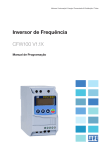
CFW100 Micro Drive
1 SAFETY INSTRUCTIONS
Table 1: Terminology of the CFW100 inverters
Product
and
Series
CFW100
Frame
Size
Rated
Current
Phase
Number
Rated
Voltage
A
01P6
S
2
A
01P6 = 1.6 A
B
02P6 = 2.6 A
C
04P2 = 4.2 A
Degree of Hardware Software
Protection Version
Version
20
---
1 - Power terminals
2 - Grounding points
3 - Accessory
connectors
4 - Control terminals
--Blank =
standard
Sx =
special
software
S = single-phase
2 = 200...240 V
supply
2 SAFETY WARNINGS IN THE MANUAL
NOTE!
It is not the intention of this guide to present all the possibilities for the application of the
CFW100, as well as WEG cannot take any liability for the use of the CFW100 which is not
based on this guide.
For further information about installation, full parameter list and recommendations, visit the
website www.weg.net.
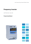
Recommended Torque
Frame
Size
A
The CFW100 is supplied packed in a cardboard box. There is an identification label affixed to the outside
of the package, identical to the one affixed to the side of the inverter.
Verify whether:
The CFW100 identification label corresponds to the purchased model.
Any damage occurred during transportation.
Report any damage immediately to the carrier.
If the CFW100 is not installed soon, store it in a clean and dry location (temperature between -25 ºC and
60 ºC (-13 ºF and 140 ºF)), with a cover to prevent dust accumulation inside it.
200...
240 V
B
2
1
6 RECEIVING AND STORAGE
Power
Supply
4
Hx = special hardware
13230453
This quick installation guide contains the basic information necessary to commission the CFW100. It has
been written to be used by qualified personnel with suitable training or technical qualification for operating
this type of equipment. The personnel shall follow all the safety instructions described in this manual
defined by the local regulations. Failure to comply with the safety instructions may result in death, serious
injury, and/or equipment damage.
10.3 INSTALLATIONS ACCORDING TO EUROPEAN DIRECTIVE OF ELECTROMAGNETIC
COMPATIBILITY
3
Blank = standard
20 = IP20
For the correct connection of the control, use:
1. Gauge of the cables: 0.5 mm² (20 AWG) to 1.5 mm² (14 AWG).
2. Maximum torque: 0.5 N.m (4.50 lbf.in).
3. Wiring of the connector of the control board with shielded cable and separated from the other wiring
(power, command in 110 V / 220 Vac, etc.)
2
1
C
Grounding
Points
Power
Terminals
N.m
Lbf.in
N.m
Lbf.in
1.4
12.4
1.4
12.4
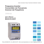
10.1 POWER CONNECTIONS
Description of the power terminals:
L/L1 and N/L2: AC power supply must be connected to L/L1 and N/L2.
U, V and W: connection for the motor.
PE: grounding connection.
Power supply
L1/L
L2/N
Disconnecting
switch
Fusibles
PE
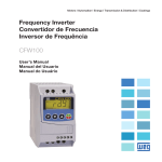
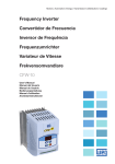
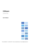
Model (Inverter
intelligent code)
Serial number
Production order
DANGER!
The procedures recommended in this warning have the purpose of protecting the user
against death, serious injuries and considerable material damage.
L1 L2
Manufacturing date (14 corresponds
to the week and I to the year)
10.3.2 Emission and Immunity Levels
PE
Table 3: Emission and immunity levels
WEG stock item
EMC Phenomenon
Rated output data
(voltage, current and frequency)
Rated input data
(voltage, current and
frequency)
Mains terminal disturbance voltage
Frequency range: 150 kHz to 30 MHz)
Electromagnetic radiation disturbance
Frequency Range: 30 MHz to 1000 MHz)
NOTE!
The information mentioned in this warning is important for the proper understanding and
good operation of the product.
PE W V
U V W PE
Figure 1: Description of the CFW100 identification label
U
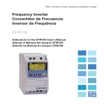
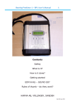
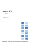
8 DIMENSIONS
FRONT VIEW
VIEW OF THE MOUNTING BASE
B
Components sensitive to electrostatic discharge.
Do not touch them.
SIDE VIEW
L
Shield
A
H1
The CFW100 is suitable for application in a circuit able to supply not more than 30.000 symetric Arms
maximum of 240V, when protected by fuses classified as indicated below:
H2
4 ABOUT THE CFW100
The CFW100 frequency inverter is a high-performance product which allows speed and torque
control of three-phase induction motors. This product provides the user with the options of vector
(VVW) or scalar (V/f) control, both programmable according to the application.
0.57 (1.25)
CFW100A01P6S220
1
200 ... 240
A
1.6
129 (5.08)
0.61 (1.34)
CFW100B02P6S220
1
200 ... 240
B
2.6
CFW100C04P2S220
1
200 ... 240
C
4.2
28 (1.10)
Dimension tolerance: ±1,0 mm (±0,039 in)
[A]
WEG
0.25/0.18
5.5
MPW25-3-D063
0.5/0.37
9.0
MPW25-3-U010
1/0.75
13.5
MPW25-3-U016
Grounding
Wire Size
129 (5.08)
55 (2.17)
28 (1.10)
50 (1.97)
[Arms] [HP/kW]
Power Wire
Size
55 (2.17)
125.6 (4.94)
50 (1.97)
Recommended
J Type Fuse
Power Supply
Rated
Voltage
117 (4.60)
-
B
C
[Vrms]
Circuit
Breaker
Number of Input
Phases
-
A
Frame
Size
Maximum
Motor
Weight
kg
(lb)
0.48 (1.05)
Output
Rated
Current
P
mm
(in)
129 (5.08)
H1
mm
(in)
100 (3.94)
Frame Size
L
mm
(in)
55 (2.17)
B
mm
(in)
28 (1.10)
Inverter
H2
mm
(in)
-
A
mm
(in)
50 (1.97)
IEC 61000-4-2
Fast transient-Burst
IEC 61000-4-4
Imunidade conduzida ("Conducted radiofrequency common mode")
IEC 61000-4-6
Surges
IEC 61000-4-5
Radio-frequency electromagnetic field
IEC 61000-4-3
4 kV for contact discharge and 8 kV for air discharge
2 kV / 5 kHz (coupling capacitor) input cables
1 kV / 5 kHz control cables and remote HMI cables
2 kV / 5 kHz (coupling capacitor) motor cables
0.15 to 80 MHz; 10 V; 80 % AM (1 kHz)
Motor, control and HMI cables
1.2/50 μs, 8/20 μs
1 kV line-to-line coupling
2 kV line-to-ground coupling
80 to 1000 MHz
10 V/m
80 % AM (1 kHz)
6
mm2
(AWG)
1.5 (16)
mm2
(AWG)
2.5 (14)
10
1.5 (16)
2.5 (14)
17.5
1.5 (16)
2.5 (14)
[A]
First Environment: environments that include domestic installations, as well as establishments directly
connected without intermediate transformer to a low-voltage power supply network which supplies
buildings used for domestic purposes.
Second Environment: includes all establishments other than those directly connected to a low voltage
power supply network that supplies buildings used for domestic purposes.
Categories:
Category C1: inverters with a voltage rating less than 1000 V and intended for use in the First Environment.
Category C2: inverters with a voltage rating less than 1000 V intended for use in the First Environment,
not provided with a plug connector or movable installations. They must be installed and commissioned by
a professional.
NOTE!
A professional is a person or organization familiar with the installation and/or commissioning
of inverters, including their EMC aspects.
Figure 2: Inverter dimensions for mechanical installation
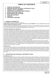
10.3.3 Characteristics of the RFI Filter
The CFW100 inverters, when installed with external filter, are used to reduce the conducted from the
inverter to the power line in the high frequency band (>150). It is necessary to meet the maximum levels of
conducted emission of electromagnetic compatibility standards, such as EN 61800-3 and EN 55011.
For further information about the RFI filter model, refer to Table 4.
The figure below demonstrate the connection of the filter to the inverter:
Signal and control wiring
Transformer
10.2 CONTROL CONNECTIONS
1
2
3
4
5
Power supply
Connector
S2
S3
DI1
Description (**)
Digital input 1
2
DI2
Digital input 2
3
DI3
Digital input 3 (*)
4
DI4
Digital input 4
5
GND
Reference 0 V
S4
(*) The digital input 3 (DI3) can also be used as input in frequency (FI).
Figure 5: Signals of control card connector of the C100A-20
XC1 1...5
L1/L
CFW100
L2/N L2
PE PE
1
S1
External
input
RFI filter
L1/L L1
10 ELECTRICAL INSTALLATION
DANGER!
The following information is merely a guide for proper installation. Comply with applicable
local regulations for electrical installations.
Make sure the AC power supply is disconnected before starting the installation.
The CFW100 must not be used as an emergency stop device. Provide other devices
for that purpose.
Category C3: inverters with a voltage rating less than 1000 V and intended for use in the Second
Environment only (not designed for use in the First Environment).
NOTE!
The wire gauges listed in Table 2 are guiding values. Installation conditions and the maximum
permitted voltage drop must be considered for the proper wiring sizing.
GND
Environment conditions permitted for the operation of the inverter:
Temperature surrounding the inverter: 0 ºC to 50 ºC ( 32 ºF to 122 ºF) – IP20.
For temperatures surrounding the inverter higher than the specifications above, it is necessary to apply
of 2 % of current derating for each degree Celsius, limited to an increase of 10 ºC (50 ºF).
Air relative humidity: 5 % to 95 % non-condensing.
Maximum altitude: up to 1000 m (3.300 ft) - rated conditions.
From 1000 m to 4000 m (3.300 ft to 13.200 ft) – 1 % of current derating for each 100 m above 1000 m
of altitude.
Pollution degree: 2 (according to EN50178 and UL508C), with non-conductive pollution. Condensation
must not originate conduction through the accumulated residues.
DI4
Avoid:
Direct exposure to sunlight, rain, high humidity or sea-air.
Inflammable or corrosive gases or liquids.
Excessive vibration.
Dust, metallic particles or oil mist.
DI3
Environmental Conditions
DANGER!
The inverter must be connected to a protective ground (PE).
Use a minimum wire gauge for ground connection equal to the indicated in Table 2.
Connect the inverter grounding connections to a ground bus bar, to a single ground point
or to a common grounding point (impedance ≤ 10 Ω).
The neuter conductor of the line that feeds the inverter must be solidly grounded; however
this conductor must not be used to ground the inverter.
Do not share the grounding wiring with other equipment that operate with high currents
(e.g.: high voltage motors, welding machines, etc.).
DI2
9 INSTALLATION AND CONNECTION
DI1
ATTENTION!
When the inverter is stored for a long period, it becomes necessary to perform the capacitor
reforming. Refer to the procedure recommended in www.weg.net.
Immunity:
Electrostatic discharge (ESD)
Environments:
3 PRELIMINARY RECOMMENDATIONS
ATTENTION!
Electronic boards have components sensitive to electrostatic discharges.
Do not touch directly on components or connectors. If necessary, first touch the grounding
point of the inverter, which must be connected to the protection earth (PE) or use a proper
grounding strap.
It depends on the inverter model on the length of the
motor cable. Refer to Table 5
Figure 4: Power and grounding connections
Table 2: List of models of CFW100 series, main electrical specifications
Do not perform any withstand voltage test!
If necessary, contact the manufacturer.
IEC/EN 61800-3
Definition of Standard IEC/EM 61800-3: “Adjustable Speed Electrical Power Drives Systems”
Connection of the shield to the ground.
NOTE!
Frequency Inverter may interfere with other electronic equipment. Follow the precautions
recommended in manual available in www.weg.net.
Level
P
Mandatory connection to the protective ground (PE).
DANGER!
Always disconnect the main power supply before touching any electrical component
associated to the inverter. Several components can remain charged with high voltages or
remain in movement (fans) even after the AC power is disconnected or switched off. Wait at
least ten minutes after turning off the input power for the complete discharge of the power
capacitors. Always connect the grounding point of the inverter to the protection earth (PE).
Connectors XCA and XCB do not present USB compatibility; therefore, they cannot be
connected to USB doors.
These connectors serve only as interface between the CFW100 frequency inverter and
its accessories.
Basic
Standard
Emission:
ATTENTION!
The procedures recommended in this warning have the purpose of avoiding material damage.
High voltages are present.
10.3.1 Conformal Installation
1. Shielded output cables (motor cables) with shield connected at both ends, motor and inverter, by means
of a low impedance to high frequency connection. Maximum motor cable length and conduced and
radiated emission levels according to Table 5. For more information (RFI filter commercial reference,
motor cable length and emission levels) refer to the Table 5.
2. Shielded control cables, keeping the separation distance from other cables according to Table 3.2 the
user's manual.
3. Grounding of the inverter according to instruction of the 3.2.4 Grounding Connections the user's manual.
4. Grounded power supply.
5. The inverter and external filter must be mounted on a common metal plate.
6. The wiring between filter and inverter must be as short as possible.
7. The grounding must be done according to recommendation of the CFW100 user's manual.
8. Use short wiring to ground the external filter or inverter.
9. Ground the mounting plate using a flexible braid as short as possible. Flat conductors have lower
impedance at high frequencies.
10. Use sleeves for cable conduits whenever possible.
Figure 3: Power terminals, grounding points and recommended tightening torque
7 IDENTIFICATION LABEL
The CFW100 inverter series, when properly installed, meet the requirements of the directive of the
electromagnetic compatibility.
These inverters were developed for professional applications only. Therefore, the emission limits of
harmonic currents by the standards EN 61000-3-2 and EN 61000-3-2/A 14.
PE
L2/N
PE
U
V
W
PE
Metal panel (when necessary)
Grounding
rod
Protective ground
Figure 6: Connection of the RFI filter - general conditions
Motor
Name
13128410
CFW100-KFABC
-
-
The following table contains the basic programming to operate the CFW100 via product HMI:
Description
External RFI filter kit WEG
Seq
Display Indication/Action
Seq
Display Indication/Action
Filter B84142A0010R000 Epcos (*)
Table 7: Considered standards
1
Radiated Emission
Category C2
Category C3
Category C3
1 m (39 in)
10 m (393 in)
10 m (393 in)
1
Initialization mode.
2
Pre ss key
Press key
if you need to change the content of
P100 – “Acceleration Time” or press key
for the
next parameter.
to e nte r the f irst level of the
parameterization mode.
Press keys
or
EN61800-5-1 - safety requirements electrical, thermal and energy
EN 50178 - electronic equipment for use in power installations
EN 60204-1 - safety of machinery. Electrical equipment of machines. Part 1: general requirements
CFW100B02P6S220
3
CFW100C04P2S220
to select the parameter P100.
Mechanical
standards
3
(1) The switching frequency is 5 KHz.
If necessar y, change the content of “P101 -
4
Deceleration Time”.
Use key
to select the parameter P133.
10.4 ACCESSORIES
The accessories are hardware resources that can be added in the application with the CFW100.
The accessories are incorporated to the inverters in an easy and quick way by using the concept “Plug and
Play”. The accessory must be installed or modified with the inverter de-energized. They may be ordered
separately, and are sent in their own package containing the components and manuals with detailed
instructions for their installation, operation and setting.
If necessary, change the content of “P133 - Minimum
Speed”.
Press key
for the next parameter.
Electromagnetic
compatibility
(EMC)
standards (*)
If necessary, change the content of “P134 - Maximum
Speed”.
Press key
6
Press key
to view the parameter content.
EN 61000-4-4 - electromagnetic compatibility (EMC) - part 4: testing and measurement techniques
- section 4: electrical fast transient/burst immunity test.
EN 61000-4-5 - electromagnetic compatibility (EMC) - part 4: testing and measurement techniques
8
(*) Standards met with the installation of the external RFI filter. For further details refer to www.weg.net.
Press key
that the motor will accelerate up to
3.0 Hz (factory default setting of P133 - Minimum
Frequency).
and hold it until it reaches 60.0 Hz.
Seq
Display Indication/Action
Initialization mode.
Pre s s key
to e nte r the f ir st leve l of the
2
Press keys
or
to select parameter P202.
Bar to monitor
the variable
Press key
if you need to change the content of
“P202 – Type of Control” for P202 = 0 (V/f).
to select parameter P401.
4
If necessary, change the content of parameter “P401
– Motor Rated Current” according to the nameplate.
Press key
Press key
Initialization Mode
5
the occurrence of faults, alarms or undervoltage).
to go to level 1 of the parameterization mode –
selection of parameters. Pressing any other key also switches to
parameterization mode.
Monitoring
Use keys
Press key
and
to find the desired parameter.
to go to level 2 of the parameterization mode change of the parameter values.
Level 2:
The parameter value is shown on the main display.
Use keys
and
to set the new value in the selected
parameter.
Press key
to confirm the modification (save the new value).
After confirming the modification, the HMI returns to level 1 of the
parameterization mode .
Rated Speed”.
Press key
Parameterization Mode
Level 1:
This is the first level of the parameterization mode. The parameter
number is shown on the main display.
If necessary, change the content of “P402 - Motor
6
If necessary, change the content of “P403 - Motor
Rated Frequency”.
for the next parameter.
13 TECHNICAL SPECIFICATIONS
Parameterization
Level1
Parameterization
Level 2
Figure 7: HMI operating modes
POWER DATA
Power Supply:
Tolerance: -15 % to +10 %.
Frequency: 50/60 Hz (48 Hz to 62 Hz).
Phase imbalance: ≤ 3 % of the rated phase-to-phase input voltage.
Overvoltage according to Category III (EM 61010/UL 508C).
Transient voltages according to Category III.
Maximum of 10 connections per hour (1 every 6 minutes).
Typical efficiency: ≥ 97 %.
14 ELECTRONICS/GENERAL DATA
Table 6: Electronics/general data
12 START-UP PREPARATION
Control
Types of control:
- V/f (Scalar)
- V V W: voltage vector control
PWM SVM (Space Vector Modulation)
DANGER!
Always disconnect the main power supply before making any connection.
Performance
1. Check if the power, grounding and control connections are correct and firm.
2. Remove all the materials left behind from the installation work from inside the inverter or the cabinet.
3. Verify the motor connections and if its voltage and current are within the inverter rated value.
4. Mechanically uncouple the motor from the load. If the motor cannot be uncoupled, make sure that
any speed direction (forward or reverse) will not result in personnel injury and/or equipment damage.
5. Close the inverter or cabinet covers.
6. Measure the power supply and verify if it is within the allowed range.
7. Apply power to the input: close the input disconnecting switch.
8. Check the result of the first time power-up:
The HMI display indicates:
Method
Output frequency
0 to 300 Hz, resolution of 0.1 Hz
V/f Control
Speed regulation: 1 % of the rated speed (with slip compensation)
Speed variation range: 1:20
Speed regulation: 1 % of the rated speed
Speed variation range: 1:30
4 isolated inputs
Maximum input voltage of 30 Vdc
Input current: - 11 mA
Maximum input current: -20 mA
Output overcurrent/short-circuit
Under/overvoltage
Motor overload
Overtemperature in the power module (IGBTs)
Fault / external alarm
Programming error
4 keys: Start/Stop, Up arrow, Down arrow and Programming
LCD Display
View/edition of parameters
Indication accuracy:
Vector control (V V W )
Inputs
Safety
Integral keypad
(HMI)
Digital
Protection
Standard keypad
- current: 5 % of the rated current
- speed resolution: 0.1 Hz
Enclosure
IP20
Description
Access to Parameters
Speed Reference
Output Speed (Motor)
Motor Current
DC Link Voltage (Ud)
Output Frequency (Motor)
Inverter Status
P007
P011
P012
Output Voltage
Active Current
DI8 to DI1 Status
P022
P023
P030
P037
P047
P048
P049
P050
P100
P101
P120
FI Value in Hz
Main SW Version
Module Temperature
Motor Overload Ixt
CONFIG Status
Present Alarm
Present Fault
Last Fault
Acceleration Time
Deceleration Time
Speed Ref. Backup
P121
P124
P125
P126
P127
P128
P129
P130
P131
P133
P134
P135
P136
P137
P138
P139
P140
P142
P143
P146
P156
P202
Reference via HMI
Multispeed Ref. 1
Multispeed Ref. 2
Multispeed Ref. 3
Multispeed Ref. 4
Multispeed Ref. 5
Multispeed Ref. 6
Multispeed Ref. 7
Multispeed Ref. 8
Minimum Frequency
Maximum Frequency
Maximum Output Current
Manual Torque Boost
Automatic Torque Boost
Slip Compensation
Output Current Filter
Slip Com. Filter
Maximum Output Voltage
Intermediate Output
Voltage
Field Weakening Start
Frequency
Intermediate Frequency
Overload Current
Type of Control
P204
Load/Save Parameters
P220
LOC/REM Selection
Source
P221
LOC Reference Sel.
for the next parameter.
11.2 OPERATING MODES OF THE HMI
Press key
Param.
P000
P001
P002
P003
P004
P005
P006
P145
Frame Sizes A, B and C
Adjustable Range
0 to 9999
0 to 9999
0 to 9999
0.0 to 10.0 A
0 to 524 V
0.0 to 300.0 Hz
0 = Ready
1 = Run
2 = Undervoltage
0 to 240 V
-10.0 to 10.0 A
0 to FF (hexa)
Bit 0 = DI1
Bit 1 = DI2
Bit 2 = DI3
Bit 3 = DI4
1 to 3000 Hz
0.00 to 99.99
-200.0 to 200.0 ºC
0.0 to 100.0 %
0 to 999
0 to 999
0 to 999
0 to 999
0.1 to 999.9 s
0.1 to 999.9 s
0 = Inactive
1 = Active
2 = Backup by P121
0.0 to 300.0 Hz
-300.0 to 300.0 Hz
-300.0 to 300.0 Hz
-300.0 to 300.0 Hz
-300.0 to 300.0 Hz
-300.0 to 300.0 Hz
-300.0 to 300.0 Hz
-300.0 to 300.0 Hz
-300.0 to 300.0 Hz
0.0 to 300.0 Hz
0.0 to 300.0 Hz
0.0 to 10.0 A
0.0 to 30.0 %
0.0 to 30.0 %
-10.0 to 10.0 %
0 to 9.999 s
0 to 9.999 s
0.0 to 100.0 %
0.0 to 100.0 %
Factory Setting
1
Prop.
ro
ro
ro
Bit 4 = DI5
Bit 5 = DI6
Bit 6 = DI7
Bit 7 = DI8
cfg
cfg
cfg
cfg
ro
ro, cfg
cfg
cfg
cfg
Most common faults and alarms
ro
ro
ro
ro
ro
ro
3 = Fault
4 = Not Used
5 = Configuration
Prop.
cfg
cfg
17 FAULTS AND ALARMS
Fault / Alarm
Display Indication/Action
parameterization mode.
3
NOTE!
ro = read only parameter.
V/f = parameter available in V/f mode.
cfg = configuration parameter, value can only be changed with the motor stopped.
“ready”.
Inverter status
Unit of measurement
(it refers to the value
of the main display)
The table below contains the mains parameters of the CFW100.
When the motor stops, the display will indicate
. The motor will decelerate to a stop.
12.2 TYPE OF CONTROL V/f (P202 = 0)
1
16 MAIN PAREMETERS
10
Press key
It is the initial state of the HMI after its successful power-up (without
Switching Frequency
Motor Rated Current
Motor Rated Speed
Motor Rated Frequency
- section 3: radiated, radio-frequency, electromagnetic field immunity test
If necessary, change the content of “P135 - Output
Press
Seq
Main display
Line Rated Voltage
P297
P401
P402
P403
EN 61000-4-3 - electromagnetic compatibility (EMC) - part 4: testing and measurement techniques
Maximum Current”.
Press key
to select parameter P002.
for the next parameter.
9
Direction of
rotation
P296
scientific and medical (ISM) radio-frequency equipment
CISPR 11 - industrial, scientific and medical (ISM) radio-frequency equipment - electromagnetic
- section 2: electrostatic discharge immunity test
5
7
11.1 INDICATIONS OF DISPLAY
DI2 Input Function
DI3 Input Function
DI4 Input Function
Inv. Rated Current
including specific test methods
EN 55011 - limits and methods of measurement of radio disturbance characteristics of industrial,
- section 5: surge immunity test.
EN 61000-4-6 - electromagnetic compatibility (EMC) - part 4: testing and measurement techniques
- section 6: immunity to conducted disturbances, induced by radio-frequency fields.
Increases the
frequency, parameter
number and parameter
value.
P264
P265
P266
P295
EN 60529 - degrees of protection provided by enclosures (IP code)
UL 50 - enclosures for electrical equipment
EN 61800-3 - adjustable speed electrical power drive systems - part 3: EMC product standard
disturbance characteristics - limits and methods of measurement
Enables/disables the inverter
via acceleration/deceleration
ramp (start/stop, according to
P229). Resets the inverter after
a fault event.
Decreases the
frequency, parameter
number or parameter
value.
DI1 Input Function
EN 61000-4-2 - electromagnetic compatibility (EMC) - part 4: testing and measurement techniques
11 USE OF THE KEYPAD TO OPERATE THE INVERTER
Selects (toggles)
display between the
parameter number
and its value (position/
content).
P263
Note: the final assembler of the machine is responsible for installing a safety stop device and a
supply disconnecting device
EN 60146 (IEC 146) - semiconductor converters
EN 61800-2 - adjustable speed electrical power drive systems - Part 2: general requirements - rating
specifications for low voltage adjustable frequency AC power drive systems
CFW100A01P6S220
2
Adjustable Range
Factory Setting
See options in P221
2
0 = Always FWD
6 = Serial/USB (REV)
0
1 = Always REV
7 to 8 = Not Used
2 = Not Used
9 = CO/DN (FWD)
3 = Not Used
10 = CO/DN (REV)
4 = DIx
11 = Not Used
5 = Serial/USB (FWD)
12 = SoftPLC
0 = Not Used
25 = Regul. DC Link
1
1 = Run/Stop
26 = Lock Prog.
2 = General Enable
27 to 31 = Not Used
3 = Quick Stop
32 = 2nd Ramp Multispeed
4 = Forward Run
33 = 2nd Ramp E.P. Ac.
5 = Reverse Run
34 = 2nd Ramp E.P. De.
6 = Start
35 = 2nd Ramp FRW Run
7 = Stop
36 = 2nd Ramp Rev Run
8 = FWD/REV
37 = Turn ON / Ac. E.P.
9 = LOC/REM
38 = De. E.P. / Turn OFF
10 = JOG
39 = Stop
11 = Increase E.P.
40 = Safety Switch
12 = Decelerate E.P.
41 = Function 1 Application
13 = Multispeed
42 = Function 2 Application
14 = 2nd Ramp
43 = Function 3 Application
15 to 17 = Not Used
44 = Function 4 Application
18 = No Ext. Alarm
45 = Function 5 Application
19 = No Ext. Fault
46 = Function 6 Application
20 = Reset
47 = Function 7 Application
21 to 23 = Not Used
48 = Function 8 Application
24 = Disab. Flying Start
See options in P263
8
See options in P263
0
See options in P263
0
1.6 to 15.2 A
According to
inverter model
0 to 1 = Reserved
2
2 = 200 - 240 V
2.5 to 15.0 kHz
5.0 kHz
0.0 to 10.0 A
1.4 A
0 to 9999 rpm
1720 (1310) rpm
0 to 300 Hz
60 (50) Hz
equipment
Table 5: Conducted and radiated emission levels, and additional information
Inverter Model
Description
REM Reference Sel.
LOC Rotation Sel.
UL 508C - power conversion equipment
UL 840 - insulation coordination including clearances and creepage distances for electrical
Safety
standards
(*) For Electrodiagnostica Radiation Disturbance use choke (T60006- L2016-W403 – VACUUMSCHMELZE).
Conducted Emission – Maximum Motor Cable
Length
Param.
P222
P223
ro
ro
ro
ro
ro
ro
ro
ro
5.0
10.0
1
3.0 Hz
3.0 Hz
10.0 (5.0) Hz
20.0 (10.0) Hz
30.0 (20.0) Hz
40.0 (30.0) Hz
50.0 (40.0) Hz
60.0 (50.0) Hz
66.0 (55.0) Hz
3.0 Hz
66.0 (55.0) Hz
1.5xI nom
0.0 %
0.0 %
0.0 %
0.005 s
0.5 s
100.0 %
50.0 %
VVW
cfg, V/f
cfg, V/f
0.0 to 300.0 Hz
60.0 (50.0) Hz
cfg, V/f
0.0 to 300.0 Hz
0.1 to 2xI nom
0 = V/f
1 = V/f Quadratic
2 to 4 = Not Used
5 = VVW
0 to 4 = Not Used
5 = Load 60 Hz
6 = Load 50 Hz
7 = Load User
8 = Not Used
0 = Always Local
1 = Always Remote
2 to 3 = Not Used
4 = DIx
5 = Serial/USB (LOC)
0 = HMI Keys
1 = AI1
2 to 3 = Not Used
4 = FI
5 to 6 = Not Used
7 = E.P.
8 = Multispeed
9 = Serial/USB
30.0 (25.0) Hz
1.2xI nom
0
cfg, V/f
9 = Save User
10 = Not Used
11 = Load Default SoftPLC
12 to 13 = Reserved
0
cfg
6 = Serial/USB (REM)
7 to 8 = Not Used
9 = CO/DN (LOC)
10 = CO/DN (REM)
11 = SoftPLC
10 = Not Used
11 = CO/DN
12 = SoftPLC
13 = Not Used
14 = AI1 > 0
15 to 16 = Not Used
17 = FI > 0
0
cfg
0
cfg
V/f
V/f
V/f
cfg
Description
Possible Causes
A046
Motor Overload
Motor overload alarm
Settings of P156 is too low for the used motor
Overload on the motor shaft
A050
Power Module
Overtemperature
Overtemperature alarm from the
power module temperature sensor
(NTC)
High temperature at IGBTs (P030 > 110 °C)
High ambient temperature around the inverter (>50 °C (>
A090
External Alarm
External alarm via DIx (option “No
External Alarm” in P26x)
Wiring on DI1 to DI4 inputs are open or have poor contact
A700
No communication with remote HMI,
Remote HMI
but here is frequency command or
Communication Fault reference for this source
122 °F)) and high output current
Blocked or defective fan
Heatsink is too dirty, preventing the air flow
Check if the communication interface with the HMI is
properly configured in parameter P312
HMI cable disconnected
F021
Undervoltage on the
DC Link
Undervoltage fault on the intermediate Wrong voltage supply; check if the data on the inverter
circuit
label comply with the power supply and parameter P296
Supply voltage too low, producing voltage on the DC link
below the minimum value (in P004):
Ud < 200 Vdc in 200 / 240 Vac
Phase fault in the input
Fault in the pre-charge circuit
F022
Overvoltage on the
DC Link
Overvoltage fault on the intermediate
circuit
Wrong voltage supply; check if the data on the inverter
label comply with the power supply and parameter P296
Supply voltage is too high, producing voltage on the DC
link above the maximum value (in P004):
Ud > 410 Vdc in 200 / 240 Vac
Load inertia is too high or deceleration ramp is too fast
P151 setting is too high
F031
Fault of
communication with
the accessory
Main control cannot establish the
communication link with accessory
Accessory damaged
Poor connection of the accessory
Problem in the identification of the accessory; refer to P027
F051
IGBTs
Overtemperatures
Overtemperature fault measured
on the temperature sensor of the
power pack
High temperature at IGBTs (P030 > 120 °C)
High ambient temperature around the inverter (>50 °C
F070
Overcurrent/
Shortcircuit
Overcurrent or short-circuit on the
output, DC link or braking resistor
Short-circuit between two motor phases
IGBTs module in short-circuit or damaged
Start with too short acceleration ramp
Start with motor spinning without the Flying Start function
F072
Motor Overload
Motor overload fault
(60 s in 1.5 x Inom)
P156 setting is too low in relation to the motor operating
F080
CPU Fault
(Watchdog)
Fault related to the supervision
algorithm of the inverter main CPU
Electric noise
Inverter firmware fault
F081
Fault on the Save
User function
Fault in the attempt to save the user
parameter table
Attempt to save (P204 = 9) more than 32 parameters
F082
Fault in the Copy
Function (MMF)
Fault in the copy of parameters
F084
Auto-diagnosis
Fault
Fault related to the automatic
identification algorithm of the inverter
hardware
Poor contact in the connection between the main control
F091
External Fault
External fault via DIx (“No External
Fault” in P26x)
Wiring on DI1 to DI4 inputs are open or have poor contact
F701
Remote HMI
communication fault
No communication with the remote
HMI; however, there is command or
frequency reference for this source
Check that the HMI communication interface is properly
(>122 °F)) and high output current
Blocked or defective fan
Heatsink is too dirty, preventing the air flow
current
Overload on the motor shaft
(with values different from the factory default) on the User
parameter table
The function Saves User is blocked
Attempt to copy the parameters from the Flash Memory
Module to the inverter with different software versions
anthe power pack
Hardware not compatible with the firmware version
Defect on the internal circuits of the inverter
configured in parameter P312
HMI cable disconnected
NOTE!
For further information, refer www.weg.net.
Document: 10003540581 / 00
WEG Item
15 CONSIDERED STANDARDS
12.1 BASIC APPLICATION
Table 4: External RFI filter models for CFW100