1
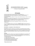
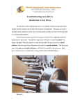
W6IFE Newsletter
September 2008 Edition
President John Oppen KJ6HZ 4705 Ninth St Riverside, CA 92501 [email protected].
Vice President Jeff Fort Kn6VR 10245 White Road Phelan CA 92371 909-994-2232 [email protected]
Recording Sec Larry Johnston K6HLH 16611 E Valeport Lancaster CA 93535 661-264-3126
[email protected]
Corresponding Sec Kurt Geitner, K6RRA1077 E Pacific Coast Hwy TMB142 Seal Beach, CA 90740 310718-4910 [email protected]
Treasurer Dick Kolbly, K6HIJ 26335 Community Barstow, CA 92311 760-253-2477
[email protected]
Editor Bill Burns, WA6QYR 247 Rebel Rd Ridgecrest, CA 93555 760-375-8566 [email protected]
Webmaster Dave Glawson, WA6CGR now in new location [email protected]
ARRL Interface Frank Kelly, WB6CWN PO Box 1246, Thousand Oaks, CA 91358 805 558-6199
[email protected]
W6IFE License Trustee Ed Munn, W6OYJ 6255 Radcliffe Dr. San Diego, CA 92122 858-453-4563
[email protected].
At the 4 September 2008 SBMS meeting the "Tech Talk" will be about IF radios and the second weekend
of the 10 GHz and Up contest. The SBMS meets at the American Legion Hall 1024 Main Street (south of
the 91 freeway) in Corona, CA at 1900 hours local time on the first Thursday of each month. Check out the
SBMS web site at http://www.ham-radio.com/sbms/.
REMINDER- NO PARKING IN THE CHURCH LOT
Last meeting- Vice President Jeff Forte, KN6VR, called the August SBMS meeting to order. There were
24 people present. The Pledge of Allegiance was recited. A new recording secretary was needed, no one
volunteered, and Mel, WA6JBD, nominated Larry, K6HLH. I could see the train coming down the track so
I volunteered for the position. We had three visitors, Roger, AD5T, from Mississippi, Michelle, W5NYV,
and Paul, KB5MU, from San Diego. Dick, K6HIJ, read the treasures report, and then distributed a graph of
the last few years of income and expenses. It showed that we are holding pretty constant. After a discussion
of the new WA6CGR repeater upgrades, Larry, K6HLH made a motion to give Dave, WA6CGR $1000
from the auxiliary fund to help finance the 445.5 MHz repeater. Dave said the total cost would be around
$2000. Approximately 20 people were at the tune-up party in Costa Mesa. The results are on the web.
MUD 2010 is coming along and we got a quote from the hotel. There is talk of having the EME conference
combine with MUD, Pat, N6RMJ, will look into this. Don, KF6QWC, volunteered to be the Co Chairman
of MUD. Very few logs were turned in for the 2GHz and up contest. Pat, N6RMJ, will not be able to head
this contest next year, as he will be busy with MUD. We went around the room with activity reports.
Wayne, N6NB is looking for someone to travel with him and Miguel, W6YLZ to Mexico for the contest.
Mel, WA6JBD has been working on the CATUS repeater system for the 10 GHz and up contest. Ed,
KD6FDU, got his extra class ham license. Chris, N9RIN, has been working on the 3456 transverter project.
Dave and Miguel have loaner radios for the contest. People then reported where they were going for the up
coming 10 GHz contest. Check Mel’s’ posting on the SBMS reflector for the current listing. Mel,
WA6JBD, gave a short demonstration of his propagation software; he will give a talk later when he has
more data. We took input from the ATV network participants. The meeting was adjourned at 9:30 PM.
Recording Secretary, Larry Johnston, K6HLH
Scheduling.
13-15 September ARRL Sept VHF QSO Party
20-21 September ARRL 10 GHz and Up contest second half
20-21 September ARRL International EME Competition
2 October SBMS meeting
17-18 October www.microwaveupdate.org
18-19 October ARRL International EME Competition
15-16 November ARRL International EME Competition
Wants and Gots for sale.
I am in need of 2 coax cables, at least 6 foot in length, with SMA connectors on
both ends. Please email me directly. Steve, ad6ht [email protected]
At the August San Bernardino Microwave Society meeting I purchased a Systron Donner 762-2A-spectrum
analyzer. This is an easy unit to work on, but seems to have a problem in the IF/ or signal areas (several
PWB cards). I am looking for any information on this unit I can. A manual, schematic, block diagram,
notes, etc. would be greatly appreciated. Of course, I would pay any costs incurred, such as copying,
postage, etc. I would also be willing to rent someone's manual, and make copies of the pertinent sections.
Any help or suggestions would be greatly appreciated. 73, Dick K6HIJ [email protected]
Threads
Power attenuators--Another thing to consider with power attenuators:
Anything rated higher than the standard 2W will not be symmetrical, i.e.
high power attenuators rated > 2W will only accept the higher power rating
on one side, the input. The output side is usually much lower power,
probably the usual 2W. I have blown a 50W CW rated attenuator by feeding about 25W CW into the
wrong port for just a few seconds (ports were not labeled, only the data sheet would tell)
Didier KO4BB
On Sat, 9 Aug 2008, Grant Hodgson wrote:
Dave
The attenuator is rated at 2W continuous. More than that and you are on your own - it's unlikely to die
with (say) 2.1W average, but the chances of death (of the attenuator) increase above the 2W limit. It will
definitely be OK with 2W into a good load.
The 100W peak rating is usually used for radar systems with very low duty cycles and very high peak
powers. You mustn't exceed the 2W average rating either. So the duty cycle must be 2% or less if you
have radar with 100W. If you have 50W peak, you can get away with a 4% duty cycle and so on.
Just to add to what Grant said, 2W is a guaranteed "no damage" input level, as you increase the power past
the 2W level not only the risk of catastrophic failure increases, but degradation of accuracy will start to
occur at a lower level. I guess that "burnout" is the ultimate degradation of accuracy!! **
The maximum pulse width has a level related function, from memory100nS at 100W to something like
10W at 1mS, mean power not to exceed 2W. IIRC, HP used to provide a graph in the user manual, but that
seems to have disappeared. Using 10W with a duty cycle of10: 1 and a PRF of 20 seconds is not good!
Another point, if you feed 2W into a 3dB and a 20dB attenuator, what power is the attenuator dissipating in
each case? Some manufacturers used to take this into account, but others (inc. HP)state "input power".
Like all things, use them properly and they will last forever, abuse them and they will not. I had a case of a
3kW Bird Attenuator, oil filled, fan cooled etc. It was clearly marked "INPUT" and "OUTPUT". It even
had a 1 1/8 EIA connector on the input, N on the output. It took a graduate apprentice to find the necessary
adaptors to fit it the wrong way around and hence blow it up!!
** Think of the strict comparison between a clock that looses2min/day and another that doesn't go - which
is the worst?
73 Geoff
Some high power attenuators are bi-directional that is you can connect either end to the Tx. The Narda
769-xx series is a case in point; these attenuators handle up to 150W at up to 6GHz from either end. But I
agree that they are in the minority - most power attenuators have an 'input' and an 'output'; sometimes you
can see between the fins that the center core is larger at the input side. If in doubt - check...
regards Grant
Sun noiseHi Ed- Measurements were made at 1296 (down converted to 28 MHz IF). Use the
Continuum screen in Spectravue. Set vertical scale to "fit" your dish size, (ie if you have a BIG dish like
yours, 10db per div, hi hi) to keep graph "in window". . Set Demod OFF. Set Meter to RMS, and db
readout. Set BW 100 or 150KHz. FFT Avg to 1, FFT/BLK as I recall to 4096 (8192). Find "Cold sky"
with dish, start Spectravue, and adjust slider on RHS of display as to get trace to near bottom of window.
Record meter reading. Move dish to or past Sun. You will see side lobes on dish, then Sun peak. Record
peak reading. Stop Spectravue. Save picture through Spectravue "Save Screen Graphics". Edit picture
saved and add Cold Sky and Peak readings along with the SFI for that day, and any other system info. You
now have a "perm ante record." of dish performance for your setup on that day. There was good agreement
with GR1296 for measurements made at W4OP a few weeks ago. Visit K5SO site for a good discussion on
making Sun Noise Measurements http://www.k5so.com/Using_sun_noise.html 73 Ben W4SC
GM Frank......I had been using the noise figure part of WSJT4 and was pleased with it and I used EXCEL
for the recording es the math.... As I had the SDR IQ, it seemed a good idea to use it IF others had had
success as indeed thy have. 73, John W3HMS 8 24
I had In a message dated 8/23/2008 3:40:37 P.M. Eastern Daylight Time,
[email protected] writes:
Hi John, FYI, once you have your warm earth and cold sky noise measurements, some simple math with
give you your system noise figure. Frank WB6CWN
GM Ben.....QSL on all......I want to use it to refine my 23 cm EME system so once I have the preadjustment reading all others will be referenced to that one...73 es tnx agn, John W3HMS 8 24 08
In a message dated 8/23/2008 3:43:09 P.M. Eastern Daylight Time,
[email protected] writes: OK John, glad to help. I think part of the difference (about 0.4db) is the
GR1236 BW is considerably wider. I can't see using a BW that takes you much outside the band of interest
for the measurement you want to make. The scale/meter on the SDRxx is very accurate, but
unless calibrated, not for an absolute measurement. It is EXCELLENT as supplied for relative
measurements.
Ben
Ben
Hello John and the group(s), Indeed, it would be useful if some of the SDRs included automated system
NF measurement capability. In its simplest form, displaying the results from a calculation using hot/cold
measurement data would be a good start. The next step would be to use a simple logic signal toggled by the
SDR application software to gate an external noise source which would turn your system into a noise figure
measurement system. At one point, W7PUA had this feature on his DSP-10 upgrade list but it never came
to be. I use a DSP-10, SDR-14 and a QS1R, all in microwave radios here. Frank WB6CWN
PropagationFor everyone who has put a specific location up on the reflector, or is in Mel's list for this weekend's
contest, I put you and your info on a GoogleMap. If you add the Path Profiler application, you can see who
you can talk to or who is behind a mountain. http://tinyurl.com/65wl8u-Tony KC6QHP
Microwave Update 2008
I looked at the calander today and was surprised to note that its only 60 days or so to MUD'08 (17-18
October 2008).
More importantly, it's only a little over 30 days until Registration costs go up. Pre-registration is $40, and
must be done with monies RECEIVED by close of business on Monday 15 September. After that,
including walk-ins, Registration is $50.
Thanks to Barry, VE4MA and Jon, W0ZQ both the presentations and papers for MUD08 are looking
good. Topics range from
Waveguide Basics to 78GHz amplifiers to optical communications to XTAL oscillators and just about
everything in between. It'll be a packed weekend!
The hotel rate is only $82/night (plus taxes, of course -- the Government has to have their piece).
For further details, see www.microwaveupdate.org.
See you in a couple of months!
73 Donn WA2VOI/0
October 17-18, 2008www.microwaveupdate.org
Signal/ Noise-Is it possible to calculate the improved signal to noise ratio between a 1.5db NF LNA and a .6db NF LNA?
Loren WA7SKTMember: ARRL and Pacific Northwest VHF Society Location: CN86cx
Loren-Somewhere on the Agilent website is a free download of AppCAD. It is a wonderful design tool.
One of the features is a "signals and Systems" section that allows you to do exactly what you are talking
about. Every segment of a system is entered with its associated loss or gain and noise figure, where
appropriate. Then the complete system noise figure, gain and S/N is calculated. Any component can then be
altered to see what effect that alteration will have on the system performance. It might be a bit difficult to
find where that download is on the website. It is a very busy website.73,Dave, K4TO
Loren,-I'm not so sure that aapcad computes with a non-room tempantenna target....
Well, for you to understand it before using softwares ,here it goes.
The NF is a measure of the degradation of the signal to noise in systems referenced to room temperature.
If all is at 290K then you have 6dB s/n with a 1.5dB NF system you will have 7dB s/n with a 0.5dB NF
system--- rapid calculations with NF can be done in cases like this with simple addition and subtraction.
If you are pointing antennas to the sky and have non-290K target then the story is completely different.
You need to calculate it all. Best is to work with noise temperature equivalents than all adds up quite
nicely.
NF= 10*log (T/290 + 1)
a) your system NF of 1.5dB equals 120K noise temp.
b) Your system NF of 0.5dB equals 35K noise temp.
So if you're pointing to the sky to a spot o with about 30K of equivalent noise temperature
your system in a) sees a total noise 120+30=150K
your system in b) sees a total noise 35+30=65K
so your system in b) is 150/65 times quieter that is 2.3 times better that is 3.6dB better
If you had a 6dB s/n in a)you will have 9.6dB s/n in b)
So when pointing to lower temp places the improvement in s/n is bigger than there duction in the NF.
So it is possible to calculate providing you know what is the noise temp. the antenna is pointing to.
Luis Cupido.ct1dmk.
P.S. now calculate if you're at microwaves and point to a 5K spot in the sky...
P.P.S. note that I wrote system NF and not preamplifier NF!!! You must compute the total system NF
where your preamp is, must include second stages feed losses etc.
Loren yes - but - you need to know the input noise temperature. For terrestrial systems it can be assumed
as being 290K, but it could be more or even less than this. Also, you need to know the gain of the LNAs.
If the input noise temp. is 290K, AND the LNAs have the same gain, AND everything else is equal (input
and output impedances etc.) then the answer is simply the difference in LNA NF in dB, so in the quoted
case you would get an improvement of 0.9dB in system S/N ratio. But there's a lot of assumptions there.
This also partly explains why there is no real point in having a system NF of less than about 2dB for
terrestrial stations - input noise will dominate the system and determines the minimum discernible signal
level.
For space systems you really do need to know the input noise temperature, which will be a function of
many factors, including frequency and where the antenna is pointing, to name but two - there are
lots of other factors. The input noise temperature will have a significant effect on the overall S/N ratio;
and it will also have an impact on the difference in system S/N ratio with the two LNAs. You can no
longer simply take the difference between the LNAs.
In practice, for a space system, you will get a S/N ratio improvement of MORE than 0.9dB. This is why
EMErs go to great lengths to minimize the LNA NF and input losses - every little bit really does count for
EME and deep space systems, assuming the input noise is not dominated by ground noise coming from
dish-edge spillover. regards Grant G8UBN
My EME path link calculator does this in the first section: It calculates cascade NF and NT for a threestage receiver including feed lines and antenna temp. Then it enters the sky temp the antenna is looking at
to produce the standard Pn=KTB noise power number.
By comparing Pn (0.5dBNF) to Pn (1.5dBNF) you will have the improvement factor in dB you are seeking.
There are three columns so you can compare three examples side by side (I have sample numbers
entered).The program also calculates path loss to the Moon and S/N, but you can use the first section alone
for receiver noise performance. Here is the link to the excel
spreadsheet: http://www.kl7uw.com/emelink.xls
Ed Cole
Loren ,
In the May 2004 QST Microwavelengths column I gave a brief but hopefully understandable explanation.
You can find it here if you are an ARRL member
http://www.arrl.org/membersonly/qqnsearch.html?search=1&words=&name=&call=wa1mba&year=2004&month=5&selpub%5B%5D=
QST
If you are not a QST member, let me know and I can send you the pdf file.Tom WA1MBA
1/4u transformer--WA1ZMS, K0CQ es The uw Group, de K2RIW 8/05/08
Dear Brian, Jerry & The uw Group,
INTRODUCTION -- Brian has asked an interesting and provocative question that gets down to some basics
of a peculiar type of transmission line system (full question repeated below), "what is the VSWR and
voltage on a 1/4 wave matching transformer that has a four 50 ohm loads?" As usual, there is more
going on than first meets the eye.
THE MATCHING SECTION -- The four loads of 50 ohms each combine to create an output load of 50/4 =
12.5 ohms. We have often been told that a single section type of 1/4 wave matching transformer should
have an impedance of Square-Root( Z in x Z out). In this case that's (50 x 12.5)^0.5 = 25 ohms.
HOW DOES IT WORK? -- A 1/4 wave long matching section will act like an "Impedance Inverter". It is a
25 ohm line looking into a total load of 12.5 ohms (a 2:1 VSWR), therefore it presents an input impedance
of twice it's Zo (25 ohms) = 50 ohms.
However, this is a 2:1 VSWR on a 25 ohm line, not a 50 ohm line -- that makes a difference.
WHAT VOLTAGE and CURRENT? -- Ordinarily, a 50 ohm line with a 2:1 VSWR would have a voltage
(and current) that is 33% higher than normal [1.33 volts or amps relative] somewhere on that line, as well
as 33% lower than normal [0.66 volts or amps relative] somewhere else, if it is at least 1/4 wave long, and
resistively terminated. The 2:1 VSWR is the result of the 1.33/0.66 voltage (or current) ratio = 2.0.
WHAT'S THE REAL VOLTAGE -- But, in this case the input voltage on the 25 ohm line will be 1.0 volts
(relative), and the output voltage will be 0.5 volts relative -- still a 2:1 VSWR. To be specific, if you are
running a kilowatt CW on a 50 ohm line, the voltage [& current] will be 223.6 volts [4.5 amps] (rms) on
your 50 ohm transmission line; there will be 223.6 volts [4.5 amps] at the input end of the your 1/4 wave 25
ohm matching transformer, and there will be 111.8 volts [8.9 amps] at the output end. The absolute
magnitude of the voltage along the 25 ohm line will taper with a waveform that will look like a COSINE on
a Pedestal; the upper portion will look like one half of the COSINE Wave from 0.0 degrees to 180 degrees.
The waveform is illustrated in Theodore Moreno, "Microwave Transmission Design Data", Dover
Publications, 1948, p 22, Fig 2-5, figure E.
IT'S EASIER THAN YOU THINK -- The bottom line of all of this is you do not have to protect the system
from a high voltage condition. You only have to consider that the Current on the 25 ohm line will be twice
as high at the output load end. But, that almost doesn't matter. A 25 ohm line has a
fatter center conductor, and it can easily tolerate twice the current. By the way, you can synthesize a 25
ohm line by putting a pair of 1/4 wave long, 50 ohm lines, in parallel.
VOLTAGE IS NOT A PROBLEM -- My good friend Hank Keen, W2CTK (sk) has made this
measurement many times: Pulses of RF applied to a Type N connector with a Polonium Source nearby (a
source of ions) will not arc-over until you exceed 20 kW (1,000 volts rms). Air at sea level is good for (has
a Dielectric Strength of) 30 kV/cm = 76 kV/inch. Also, moisture in the air (high humidity) does not change
the Dielectric Strength. Almost all connectors fail from current overheating the center pin, not from arcover.
LOSS IS ALSO NOT A PROBLEM -- Your matching transformer is only 1/4 wave long, and your
connectors are much-much shorter yet. Unless you use resistive materials, or insulators that have a big
"Loss Tangent", you can only create RF loss by using transmission line materials that have a significant
length. There are many mis-informed amateurs who believe each UHF Connector has 0.5 dB of loss at 432
MHz -- this is crazy. Yes, they may have a 1.15:1 VSWR. This really is not a "Loss" mechanism, it a
"Reflection" mechanism. The true 432 MHz insertion loss (of a good brand) is about 2 watts out of 1,000 - that's about 0.009 dB each. 73 es Good High Power DX, Dick, K2RIW
Well yes 25 ohms has good power handling capability. That's because the heat from current in the center
conductor is lower because of the surface area. With the line only 1/4 wave long terminated in 50 at one
end and 12.5ohms at the other end, its mostly current limited because of the current at the 12.5 ohm end.
Impedance never rises along the line higher than the 50 ohm end so voltage is no more problem in the 25
ohm line (except that if the outer conductor is the same size, the center conductor is fatter and so the air gap
is smaller) than it is in the 50 ohm line. If one is operating in low pressure environments (high altitude
aircraft or balloons or space orbits) spacing might be a problem and needs to be considered. But on earth
with reasonable sized conductors and amateur power level voltage isn't a problem. Current can be a
problem in small components.
Besides the quarter wave transformer of constant impedance there are other solutions to this impedance
matching requirement. One involves short pieces of 12.5 and 50 ohm line. Another involves a continuously
tapered line, several quarter waves long. There is a taper that gives a much broader bandwidth and the low
Z end would be 12.5 ohms and the high Z end would be 50 ohms. One trades compactness for bandwidth
and gains better power handling capability with the characteristic Z of the line being that of the RF at any
point along the line.73, Jerry, K0CQ
On Wed, 2008-08-06 at 11:55 -0400, MICHAEL SAPP wrote: Hi Folks: So how does the quarter wave
transmission line situation compare to a ferrite unun when the transform is less than 2:1....like 50 to 36
ohms. I ask this because Jerry Sevick's work with ununs shows them to also function in reciprocal
transforms....i.e., the 50 to 36 ohm unun can be reversed to function as a 50 to 70 ohm transform unun. My
best guess is the Q of the ferrite & wire unun is low enough to permit a transform in either direction but
that a coax line may have a higher Q and may not have reciprocity. That SQRT(50*36) = SQRT (50*70)
paradox has always bugged me. Mike wa3tts
Lets not confuse things by calling a two winding transformer on a ferrite core an unun. Its a two winding
transformer. As such the turns ratio is defined by the physical turns ratio and autotransformer connection
over a considerable range of frequency and termination impedances. At the high end of its working
frequency range it gets to be lengths of coupled transmission lines but at mid and low its turns on the core
that count and make it work. At the high end the transmission line couplings take over from the core based
coupling predominant at the low and mid frequency range. The working frequency range of a transformer
can have a ratio of limits of between 10 and 50 to 1. The wide frequency range is greatest at the lowest
power levels, hardest to achieve the greater the power range.
The frequency range is shifted when the termination impedances change. Rule of thumb is that the low end
is set by the frequency where the inductance of the winding presents a reactance 5 to 10 times the
impedance seen by that winding. Its not an abrupt edge of the useful spectrum, just the shunt reactance
takes more energy from the signal you wish transformed in impedance. Raising the working impedance
with the same windings raises the minimum frequency. Lowering the working impedance lowers the
minimum frequency. There's NO magic. No sqrt of the product of the terminating impedances.
A quarter wave transmission line matching section depends on the length of the line being near that quarter
wave, else it doesn't provide the impedance match expected. E.g. when its short, the transformation gets
reactive (inductive) and incomplete, while if its somewhat long it gets capacitive reactive and incomplete,
and at 1/2 wave the input impedance is the same as the load impedance. It accomplishes the desired
impedance change when an odd multiple of 1/4 wave, but does no impedance change when any multiple of
1/2 wave long. That is described mathematically by the input Z being a function of load Z, Z0, and tangent
of the length in wavelengths. Tangent has that periodicity the same as the transmission line. Practical
bandwidth for a quarter wave matching section is about20%, and it gets narrower when 3/4, and 5/4 wave
long.73, Jerry, K0CQ
Your article could fit here.
Wayne, N6NB with his tool box 10 band
rig and antenna. The San Bernardino
Microwave Society is a technical
amateur radio club affiliated with the
ARRL having a membership of over 90
amateurs from Hawaii and Alaska to the
east coast and beyond. Dues are $15 per
year, which includes a badge and
monthly newsletter. Your mail label
indicates your call followed by when
your dues are due. Dues can be sent to
the treasurer as listed under the banner on
the front page. If you have material you
would like in the newsletter please send
it to Bill WA6QYR at 247 Rebel Road
Ridgecrest, CA 93555,
[email protected], or phone 760375-8566. The newsletter is generated about the 15th of the month and put into the mail at least the week
prior to the meeting. This is your newsletter. SBMS Newsletter material can be copied as long as SBMS is
identified as source.
San Bernardino Microwave Society newsletter
247 Rebel Road
Ridgecrest, CA
93555
USA